

Page 1

LASER PLUS
OPERA TING INSTRUCTIONS
Phone:
E-Mail: [email protected]
025-370403 REV X9 12/16/03
(209) 586-1022
(800) 545-1022
Fax:
(209) 586-1026
www.olsontech.com
Page 2

TABLE OF CONTENTS
SYSTEM OVER VIEW Page 3
OPTICAL CONNECTORS & CLEANING Page 4
CHASSIS Page 4
ST ATUS MONITORING Page 4&5
POWER SUPPLIES Page 5
OPTICAL TRANSMITTER MODULE
Fuse Page 5
RF Input Page 5
Optical Output Page 6
Input Drive vs. Channel Loading Page 6
Indicators and T est Points For LP-OT -6 Page 7
Indicators and T est Points For LP-OT -8 to LP-OT-15 Page 8
OPTICAL RECEIVER MODULE
Description Page 9
Front Panel Page 9
Rear Panel Page 10
Internal Adjustments Page 10
Fuse Page 10
Optical Input Chart Page 10
RETURN FREQUENCY MUL TIPLIERS Page 10
MODULE EXTRACTOR Page 11
025-370403 REV X9
Page 2 of 11
Page 3

SAFETY WARNINGS
LASER RADIATION
The laser transmitters emit invisible radiation that can cause permanent eye
damage. A VOID DIRECT EXPOSURE T O BEAM. Operate only with
the proper optical fiber installed in the transmitter optical connector. The laser
transmitter should be disabled with the front panel switch whenever the optical
connector is empty .
HIGH VOLTAGE
The AC input power supply contains no user serviceable parts. There is exposed high voltage inside the
supply . The power supply housing should be opened only by factory service technicians.
FIRE HAZARD
The AC input rear power supply fuse is a 3AG, 3.25A, slow blow fuse. T o avoid a risk of fire, this fuse
should be replaced only with an identically rated fuse.
The main chassis is not intended as a shipping container. Shipping the system with any module installed can
cause severe physical damage.
DESCRIPTION MODEL PART NUMBER
MAIN CHASSIS LP-CH 037-000403
95-240V AC POWER SUPPL Y LP-PS 037-000406
48VDC POWER SUPPL Y LP-P S-4 8 037-000451
LASER TX MODULE 6dBm LP-OT-6 037-000400
LASER TX MODULE 8dBm LP-OT-8 037-080433
LASER TX MODULE 9dBm LP-OT-9 037-090433
LASER TX MODULE 10dBm LP-OT-10 037-100433
LASER TX MODULE 12dBm LP-OT-12 037-120433
LASER TX MODULE 14dBm LP-OT-14 037-140433
LASER TX MODULE 15dBm LP-OT-15 037-150433
TRIPLE RX MODULE LP-OR-300 037-000401
RSM 1&3 w/o OPTICAL RX LP-DC-212-NR 037-000454
RSM 1&3 w/ OPTICAL RX LP-DC-212 037-000447
RSM 2&4 (req. LP-DC-212) LP-DC-234 037-000448
SHIPPING ALERT
SYSTEM OVERVIEW
SNMP ST A TUS INTERFACE LP-SNMP 037-000461
MODULE EXTRACTOR LP-EX 010-000930
A system can have a single power supply or 2 redundant supplies. W ith a single power supply, a fully populated
system holds 15 RF/optical modules. With dual power supplies, a fully populated system holds 14 RF/optical modules.
All modules can be hot swapped.
025-370403 REV X9
Page 3 of 11
Page 4

OPTICAL CONNECTORS AND CLEANING
The fiber ends can be damaged by the insertion of contaminated connectors. Some types of customer
damage to connectors or fiber are not covered under warranty . Fiber connectors should never be left uncovered.
Reel cleaners or prepackaged alcohol wipes are the most convenient means of cleaning optical connectors. Clean
alcohol and lint free wipes or swabs may also be used.
The standard optical connector is an SC/APC. T o specify an FC/APC connector , append –F A to the
model name and consult the factory for part numbers. FC/APC connectors must be specified at time of order .
CHASSIS
The chassis is a 19” rack mount unit, 5.75” (3 RU) high. The chassis slots are numbered 1 to 16 from left
to right as viewed from the front. When viewed from the rear, slot 1 is on the
RF/optical modules. Slot 16 accepts only a power supply module. Slot 15 accepts either an RF/optical module or
a power supply module.
All module changes can be made from the front of the chassis through service loops in the RF and power
cables. All RF connections are made from the rear of the rack. All optical connections are made from the front of
the rack. There are access holes in the front sides of the chassis for fiber routing. There are fiber support slots in
the top front of the chassis.
right. Slots 1-14 accept only
There are no connections or test points on the front of the chassis. The chassis status LED’ s are located on
the power supply module. All LED’ s can be seen through a clear window in the front of the chassis. All normal
indicators are green. Any red LED that is turned on denotes an abnormal condition.
The chassis rear has 4 long-life fans that can be changed from the outside. The OT P/N for the fan
assembly is 037-000405. There is a DB-25M alarm connector at the center rear of the chassis. These isolated
relay contacts, rated at 100mA @ 25VDC, provide a ground closure on any alarm, including power failure. Pins 115 monitor slots 1-15 respectively . Pin 17 is the chassis cooling alarm. Pin 24 is the summary alarm that alarms on
any failure. Pin 25 is ground.
The small rectangular connector at the right rear of the chassis is for factory testing, the Olson T echnology
SNMP interface (LP-SNMP), or OEM status monitoring modules.
STATUS MONITORING
There are three types of status links built into this system.
1) The rear panel DB25 connector provides isolated summary alarms of each module in the system. No
computer is required.
2) The 10 pin connector located in the upper right rear of the main chassis, can be adapted to the printer
(parallel) port of any windows 95 or 98 (ME, 2k, and XP will not work) based computer to monitor
several critical module and chassis functions. This software is available from Olson T echnology Inc.
3) The 10 pin connector will accept an OT -SNMP SNMP interface. One interface is required per chassis.
Please consult the factory for complete details on these features.
025-370403 REV X9
Page 4 of 11
Page 5
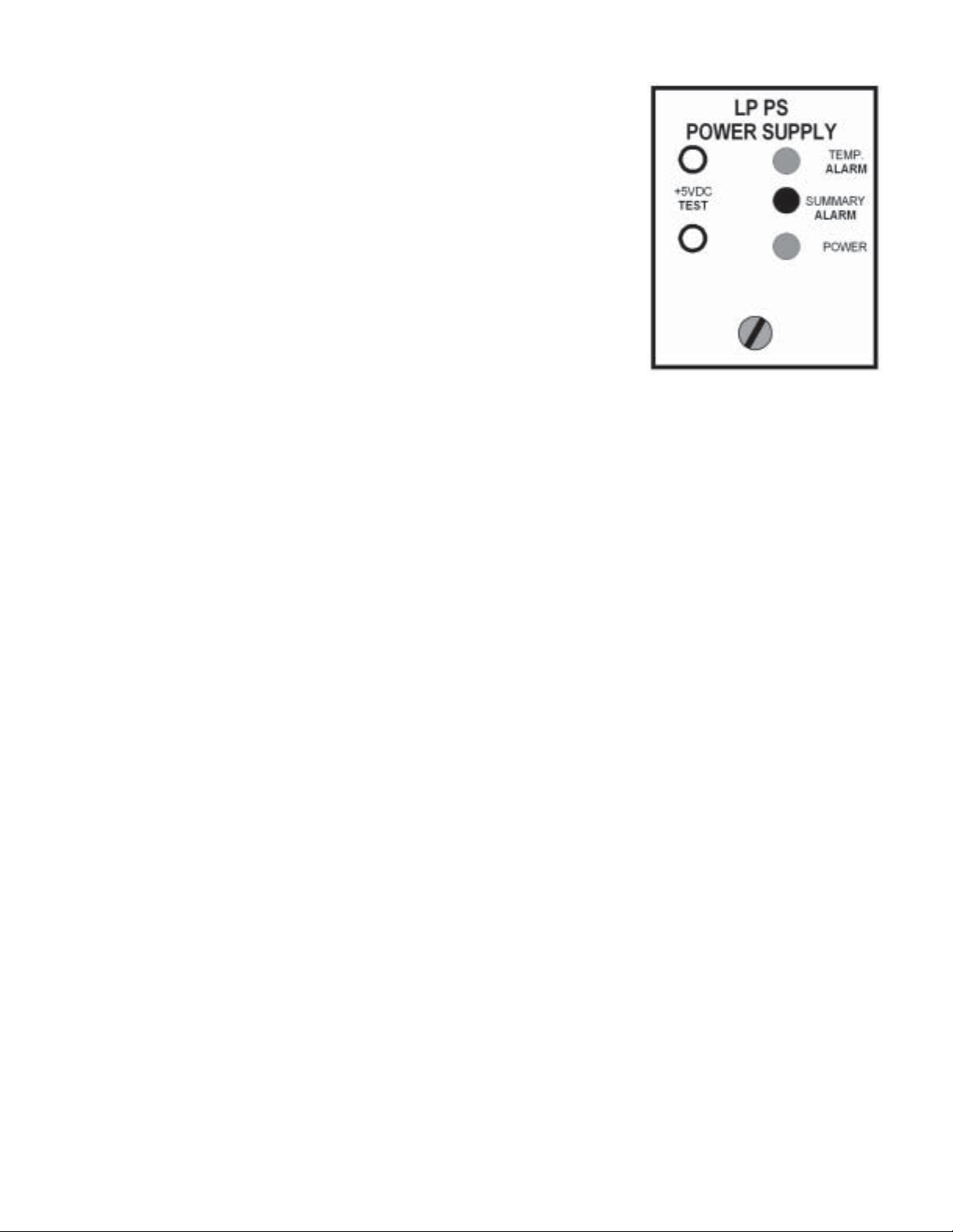
There are 3 LED’s on the front of the power supply .
The temperature alarm LED is normally green. It changes to red if any
fan is open, missing, or frozen. It also goes red if the unit’ s internal temperature
is too high. This LED is normally on for several seconds after power on
while the fans start up.
The red summary alarm LED is normally off. It lights on any module
alarm or on a temperature alarm.
The power LED is normally green. If the power supply voltage is too
high or too low , it will be red. This will also cause a temperature alarm.
The test points can be used to monitor the bus voltage.
POWER SUPPLIES
A single power supply mounts in the rightmost slot as viewed from the front. Dual supplies mount in the two
rightmost slots. Changing from single to dual supplies does not require any chassis rewiring.
The AC supply automatically accepts 90-132V AC and 180-264VAC at 47-63Hz. The maximum input
power is about 140 watts. The voltage supplied to the modules is approximately 5.25VDC.
The AC input is through an IEC connector on the rear of the power supply. The voltage selection jumper is
not used; the unit will operate with the jumper in any position. If redundant supplies are used, we recommend
plugging them into independently protected power strips.
The Laser Plus system also has a 48V DC input power supply for central office use. See the LP-PS-48V
instruction manual, OT p/n 025-370451, for complete specifications.
OPTICAL TRANSMITTER MODULE
FUSE
The module has an internal miniature 3A SB fuse in a holder . The Littelfuse part number is 0454003. The
Olson T echnology P/N is 286-000009.
RF INPUT
The LP-OT -6 laser transmitter accepts a 77 channel flat RF input from +18dBmV to +22dBmV per
channel (50-550 MHz). Digital signals can be added from 550MHz to 870MHz. The power in any 6MHz
bandwidth should be at least 6dB below the picture carriers.
The LP-OT -8 to LP-OT -15 laser transmitter accepts a 77 channel flat RF input from +19dBmV to
+23dBmv per channel (50-550 MHz). Digital signals can be added from 550MHz to 870MHz. The power in any
6MHz bandwidth should be at least 6dB below the picture carriers.
The front panel RF test point has been calibrated at 547.25MHz to read +10dBmV for optimum optical
modulation with 83 channel loading. This level will change with channel loading.
With these frequency ranges, it is extr emely important to account for coax cable loss and slope when
making measurements and distributing signals.
025-370403 REV X9
Page 5 of 11
Page 6
OPTICAL OUTPUT
The cooled DFB laser outputs 4mW (+6dBm) minimum at 1310 nm. Laser performance has been
optimized for this power level; there is no external adjustment for laser output power.
UNIT OPTICAL OUTPUT
LP-OT-6 4.00mW 6dBm
LP-OT-9 7.94mW 9dBm
LP-OT-8 6.30mW 8dBm
LP-OT -10 10.0mW 10dBm
LP-OT-12 15.70mW 12dBm
LP-OT-14 25.00mW 14dBm
LP-OT-15 31.60mW 15dBm
INPUT DRIVE vs. CHANNEL LOADING
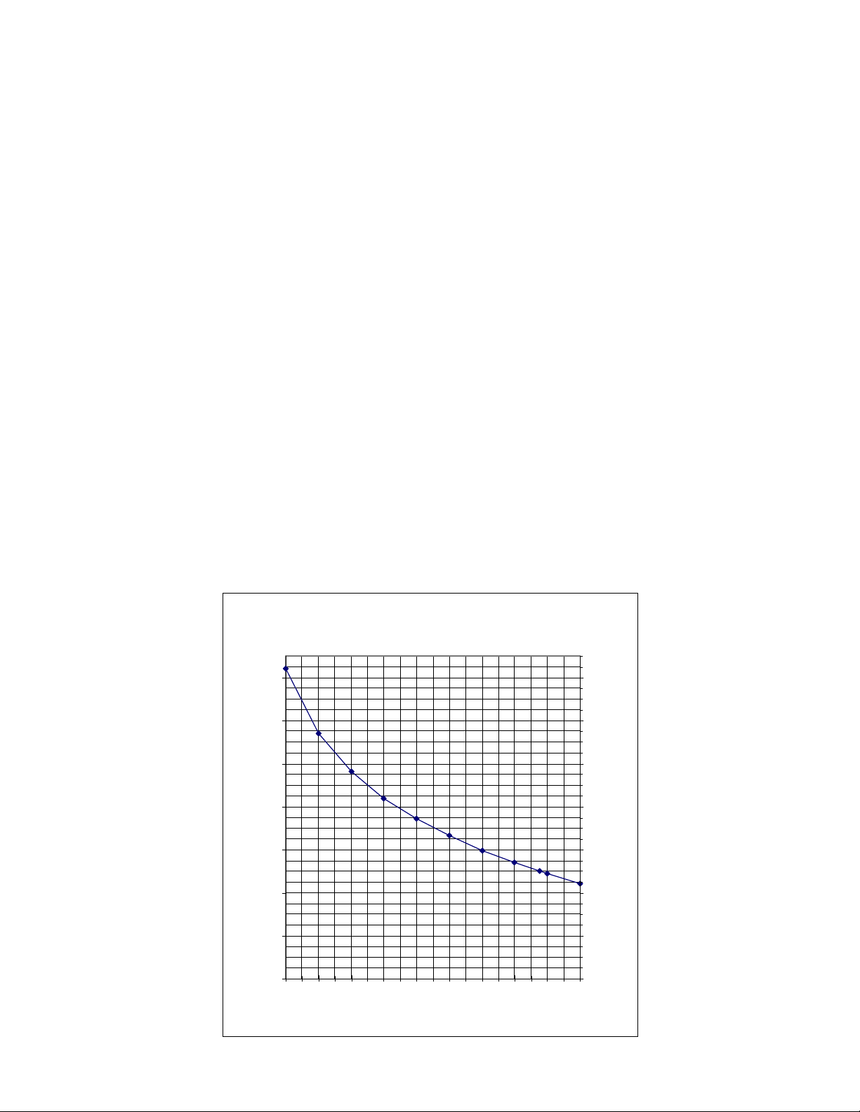
The laser RF drive level is the primary determining factor of link distortion and S/N performance. The basic
limitation on input drive is total input power . The following chart shows the approximate input levels versus channel
loading. The left axis shows the nominal RF input level. The unit will work with levels within +/- 2dB of this value.
The right axis shows the test point reading for optimum modulation.
Many systems run their digital channels at 6dB below the analog channels. This is a very convenient level
for calculating loading. At 6dB down, merely divide the number of digital channels by 4 and add to the analog
channels to get the total loading.
The factory test input is 77 analog channels with 42 digital channels at 6dB down. This is 77 + 42/4, which
equals 87.5. This is the 87.5 ch / +20dBmV input point on the graph.
Some systems use an OMI meter to set laser modulation. The LP-OT -6 to LP-OT-15 have been
individually adjusted for optimum performance. Setting all units for the same OMI, instead of using the test point,
will result in reduced transmitter performance.
Input Level versus Loading
Nominal Input Level dBmV
29.0
27.0
25.0
23.0
21.0
19.0
17.0
19
17
15
13
11
9
7
Set T.P. dBmV
025-370403 REV X9
15.0
10 20 30 40 50 60 70 80 90 100
# of Channels
5
Page 6 of 11
Page 7
If the channel loading is less than 40, you may decide not to increase the levels by the maximum possible
amount. This will provide improved distortion at the cost of S/N. The best rule of thumb is to use the maximum
possible levels for long haul links, and lower drive levels as the links get shorter.
INDICATORS AND TEST POINTS FOR LP-OT-6
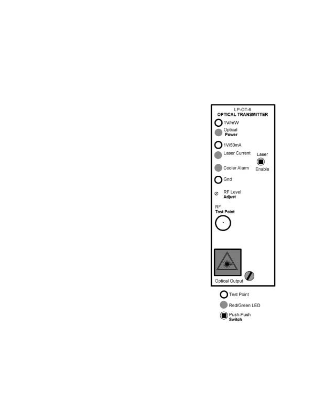
The laser transmitter has front panel test points for optical power and laser current. Only a high impedance
voltmeter should be used. The meter common should be connected to the module ground test point, not to chassis
ground.
The optical power alarm LED is normally green. It turns red
on insufficient optical power . 4mW of optical output reads 4.0V at
TP.
The laser current alarm LED is normally green. It turns red
on excessive laser current. At a typical laser current of 30mA the TP
will read 0.6V .
The cooler alarm LED is normally green. It turns red when
the cooler cannot keep the laser at a constant temperature.
The RF level adjust control allows for a 4dB range of input
level adjustment.
The RF test point is calibrated to read +10dBmV @
547.25MHz for proper laser modulation with 83 channel loading.
This level will change with channel loading. It does not require
termination.
Push the laser enable switch with an alignment tool to enable
or disable the laser . The laser should be disabled whenever there is
no fiber connected. Disabling the laser will cause a local optical
power alarm, but will not cause a remote module or chassis alarm.
‘T easing’ this switch may cause very brief remote alarms.
The optical output connector is type SC/APC, with optional
FC/APC connector available.
NOTE: The Laser Enable switch is no longer available on newer
models.
025-370403 REV X9
Page 7 of 11
Page 8
INDICATORS AND TEST POINTS FOR LP-OT-8 TO LP-OT-15
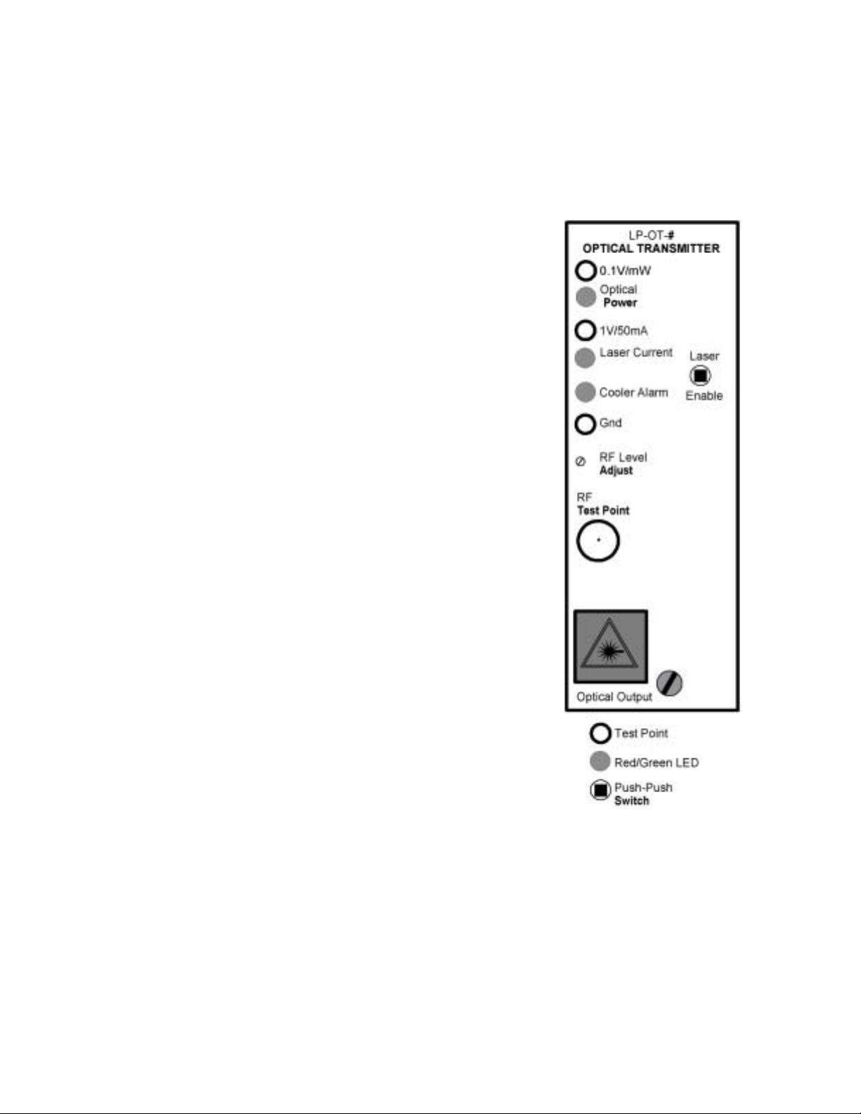
The laser transmitter has front panel test points for optical power and laser current. Only a high impedance
voltmeter should be used. The meter common should be connected to the module ground test point, not to chassis
ground.
The optical power alarm LED is normally green. It turns red
on insufficient optical power . Optical ouput reads as shown below:
UNIT OUTPUT TEST POINT VOLTAGE
LP-OT-8 6.30mW 0.63V
LP-OT-9 7.94mW 0.79V
LP-OT-10 10.00mW 1.00V
LP-OT-12 15.70mW 1.57V
LP-OT-14 25.00mW 2.5V
LP-OT-15 31.20mW 3.12V
The laser current alarm LED is normally green. It turns red
on excessive laser current. At a typical laser current of 50mA the TP
will read 1.0V .
The cooler alarm LED is normally green. It turns red when
the cooler cannot keep the laser at a constant temperature.
The RF level adjust control allows for a 4dB range of input
level adjustment.
The RF test point is calibrated to read +10dBmV @
547.25MHz for proper laser modulation with 83 channel loading.
This level will change with channel loading. It does not require
termination.
Push the laser enable switch with an alignment tool to enable
or disable the laser . The laser should be disabled whenever there is
no fiber connected. Disabling the laser will cause a local optical
power alarm, but will not cause a remote module or chassis alarm.
‘T easing’ this switch may cause very brief remote alarms.
The optical output connector is type SC/APC, with optional
FC/APC connector available.
NOTE: The Laser Enable switch is no longer available on newer
models.
025-370403 REV X9
Page 8 of 11
Page 9
OPTICAL RECEIVER MODULE
DESCRIPTION
The LP-OR is a triple return band receiver in a single module. The receivers have an extended bandwidth
of 200 MHz to allow the use of spectrum multiplication. Individual receivers in the module can be disabled if three
inputs are not available.
FRONT PANEL
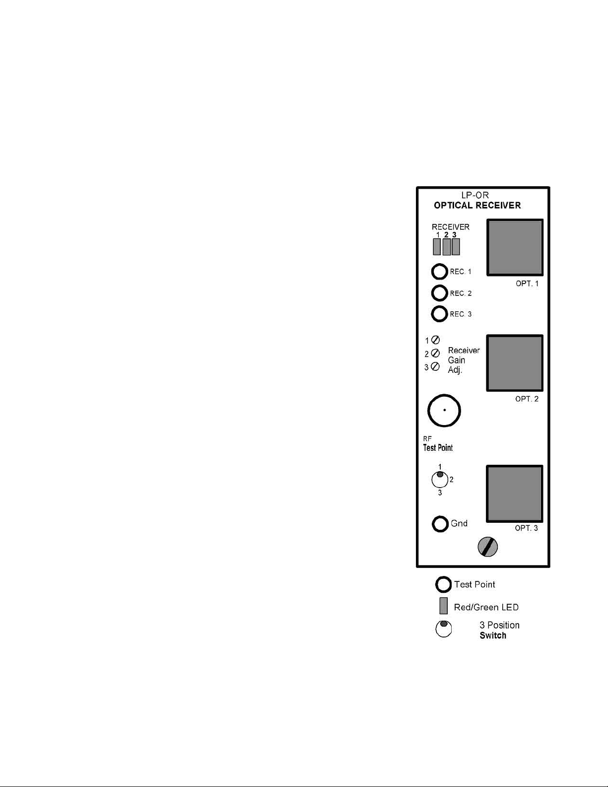
The 3 rectangular red/green status LED’s monitor the receivers’ optical
inputs. They are normally green and change to red on a low or missing optical
input. Any red LED causes a module alarm and a chassis summary alarm.
The 3 DC test points monitor the receivers’ optical inputs. 1mW
(0dBm) is 1V at the test point. Only high impedance meters should be used.
Use the ground test point at the bottom of the module, not chassis ground.
The 3 multi-turn potentiometers set the receivers’ gains. Setting any
gain control fully counter-clockwise will disable that receiver . The LED for a
disabled receiver will always be green. A disabled receiver will never generate
an alarm.
The –20dB RF test point monitors the RF output of any single receiver.
It does not require termination.
The 3 position toggle switch selects which receiver’s output appears at
the test point. Insure that this switch is in the correct position before using the
test point to set the RF gain.
The ground test point should be used when checking optical input
levels.
The SC/APC optical input connectors are on the right of the front
panel, with optional FC/APC connectors available.
025-370403 REV X9
Page 9 of 11
Page 10

REAR PANEL
The RF output connectors are on the rear of the unit. Receiver #1 is on the top. Receiver #3 is on the
bottom.
INTERNAL ADJUSTMENTS
There are 3 jumpers that are accessible from the side that are used to set the receiver input range. The
jumpers can be changed with tweezers or needle nosed pliers. The nominal level for changing jumper posistions is
-3dBm.
FUSE
The module has an internal miniature 3A SB fuse in a holder . The Littelfuse part number is 0454003. The
Olson T echnology P/N is 286-000009.
OPTICAL INPUT CHART
The following chart shows the test point readings versus optical input levels.
T.P. Volts Optical Input mW Optical Input dBm
3.02 3.02 4.8
2.51 2.51 4
2.00 2.00 3
1.58 1.58 2
1.26 1.26 1
1.00 1.00 0
0.79 0.79 -1
0.63 0.63 -2
0.50 0.50 -3
0.40 0.40 -4
0.32 0.32 -5
0.25 0.25 -6
0.20 0.20 -7
0.16 0.16 -8
0.13 0.13 -9
0.10 0.10 -10
0.08 0.08 -1 1
0.06 0.06 -12
0.05 0.05 -13
0.04 0.04 -14
0.03 0.03 -15
RETURN FREQUENCY MULTIPLIERS
The Laser Plus system includes 3 receiver/ down converter modules that can be used as part of a return
band frequency multiplier system. This system can quadruple the bandwidth of a new or existing return link. Olson
T echnology builds up converters to fit inside the nodes of several manufacturers. Consult the factory for the latest
list of compatible nodes.
See the LPDC-212 / LPDC-234 instruction manual, OT # 025-370447, for more details.
025-370403 REV X9
Page 10 of 11
Page 11
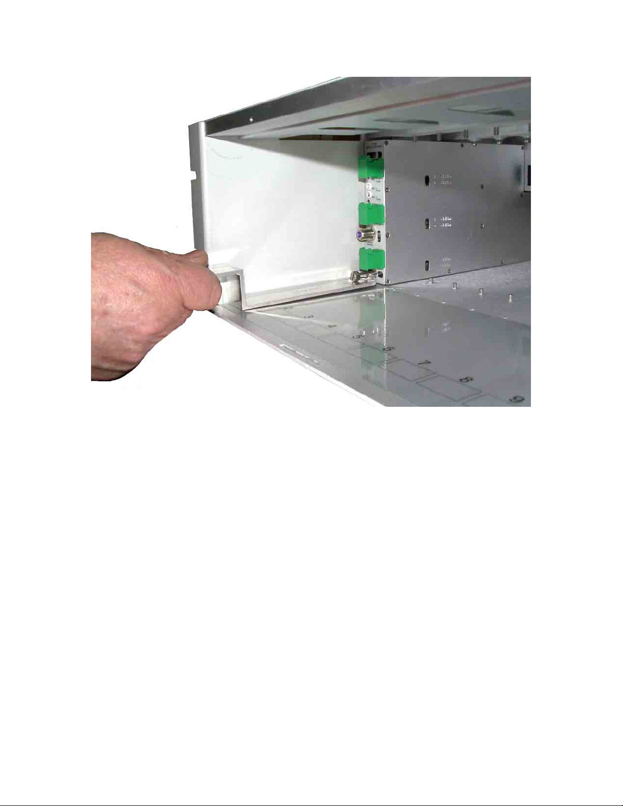
Laser Plus Module Extraction Tool
Insert module puller and slide the notched end underneath the pull tab on the front of the inserted module as
shown above. Then press down on the handle, this will lift the notched end thereby lifting the front of the module.
Then proceed by pulling the unit out while pressing down on the handle.
025-370403 REV X9
Page 11 of 11
 Loading...