

Page 1

OTR-3550-SW
FREQUENCY AGILE - F.C.C. COMPATIBLE
TELEVISION PROCESSOR
INSTRUCTION MANUAL
Phone:
E-Mail: [email protected]
025-000232 REV C 8/17/01
(209) 586-1022
(800) 545-1022
Fax:
(209) 586-1026
www.olsontech.com
Page 2
1) INTRODUCTION
The Olson T echnology OTR-3550-SW is a frequency agile, F .C.C. compatible television processor . This unit
will select any VHF/UHF/cable input channel from 55.25MHz to 801.25MHz and will provide high level
(+60dBmV) outputs on any channel from 7.00MHz (T -7) through 547.25MHz (channel 78) including all
HRC and IRC output channels. All input and output channels are selectable in 0.25MHz increments by front
panel DIP switches, including F .C.C. offsets of +12KHz and +25KHz.
The OTR-3550-SW uses dual SA W filtering for 60dB adjacent channel rejection, and has high level (>60dB)
spurious free output. This unit offers the unique Olson T echnology feature of >80dB out-of-band carrier to
noise ratio, which will allow virtually unlimited numbers of the OTR-3550-SW to be combined without the
need for external bandpass filters. The OTR-3550-SW is BTSC compatible and will automatically function
with either stereo or monaural audio carriers.
The OTR-3550-SW has a low power consumption (17 watts @ 115 V AC) for reliable long term operation.
This unit is equipped with a 0.5 amp slo-blo fuse. T o maintain proper performance of unit, replace only with an
equivalent fuse.
OTR-3550-SW
FREQUENCY AGILE - F .C.C. COMP ATIBLE
TELEVISION PROCESSOR
2) INPUT CHANNEL SELECTION - DEMODULA TOR
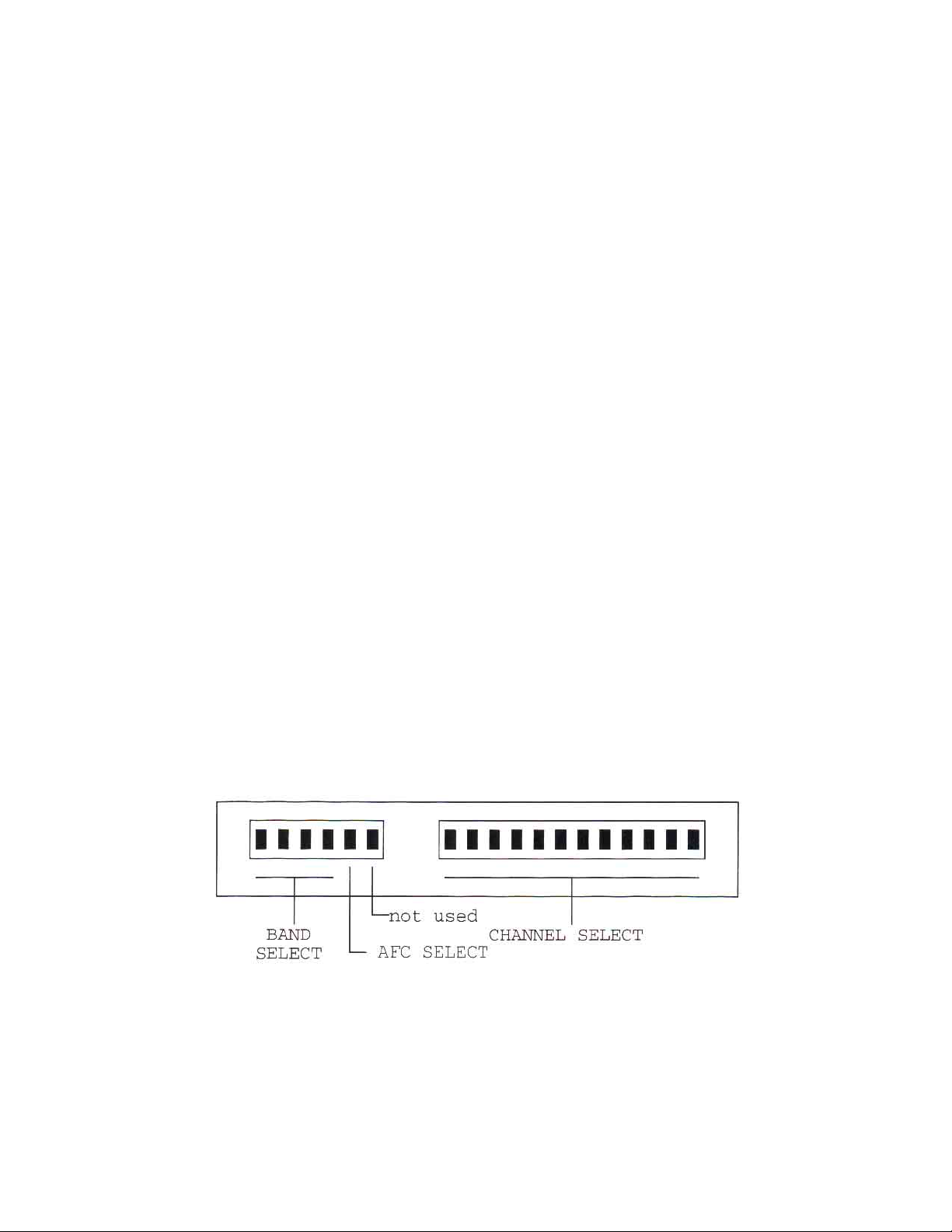
Remove the front panel plate marked “Input Channel Select” to expose the channel select and band select
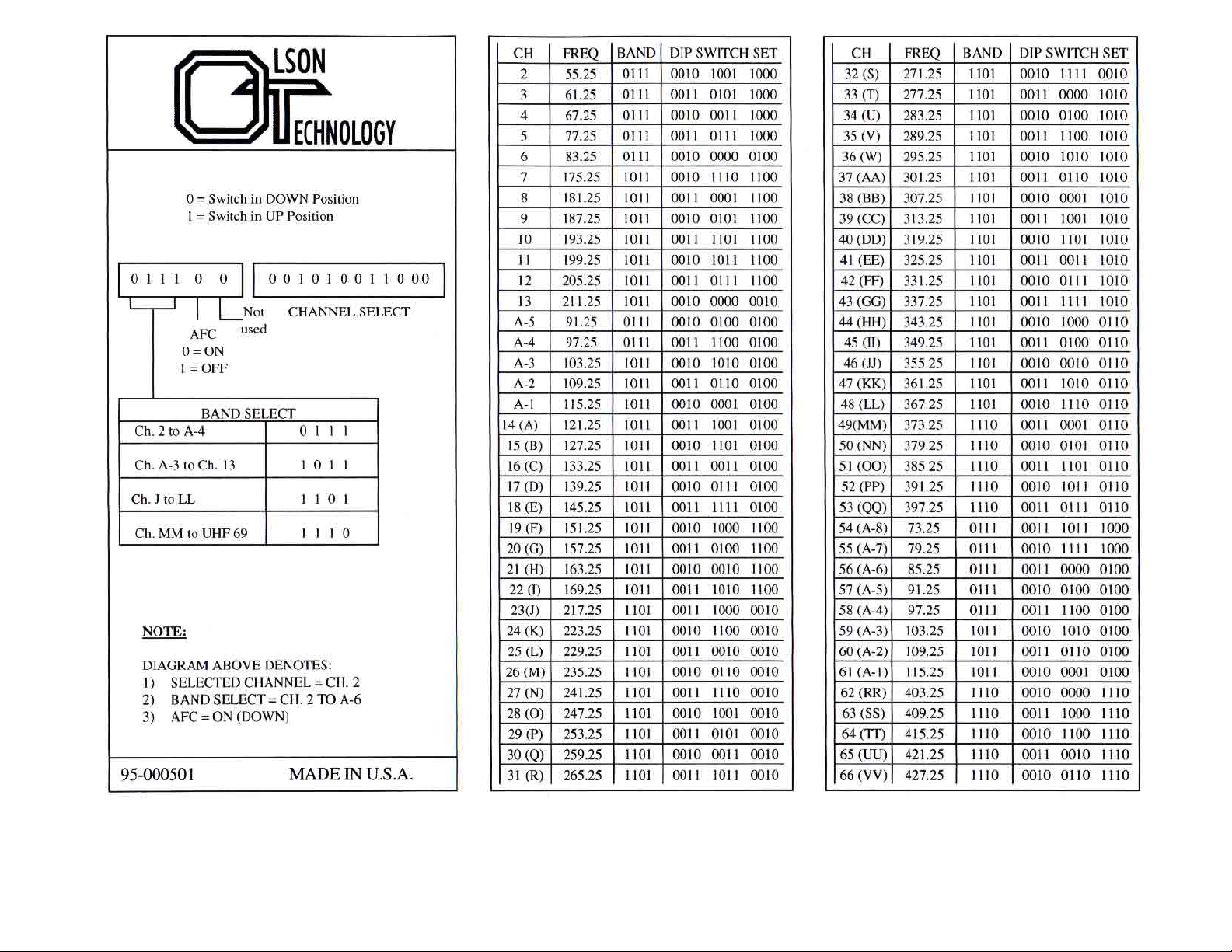
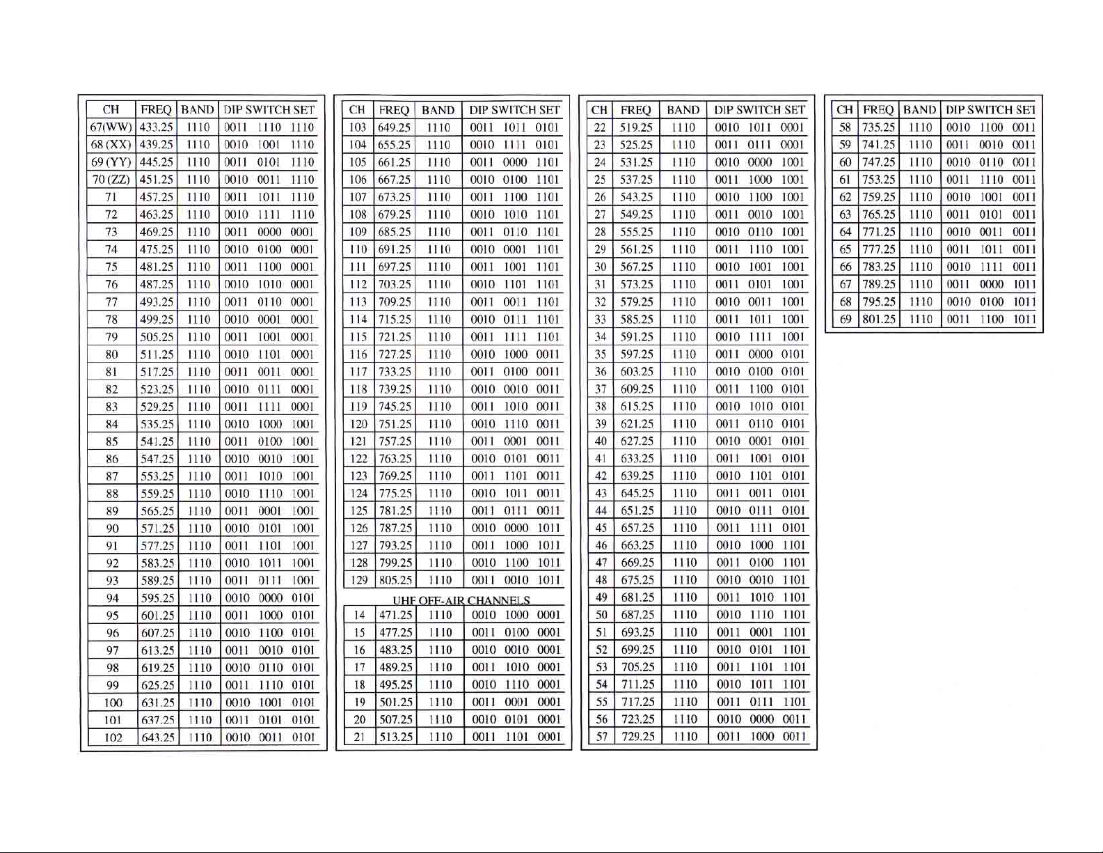
DIP switches as shown in Figure #1. See page 5 for demodulator switch codes.
Figure #1
INPUT CHANNEL SELECT
025-000232 REV C
Page 2
Page 3
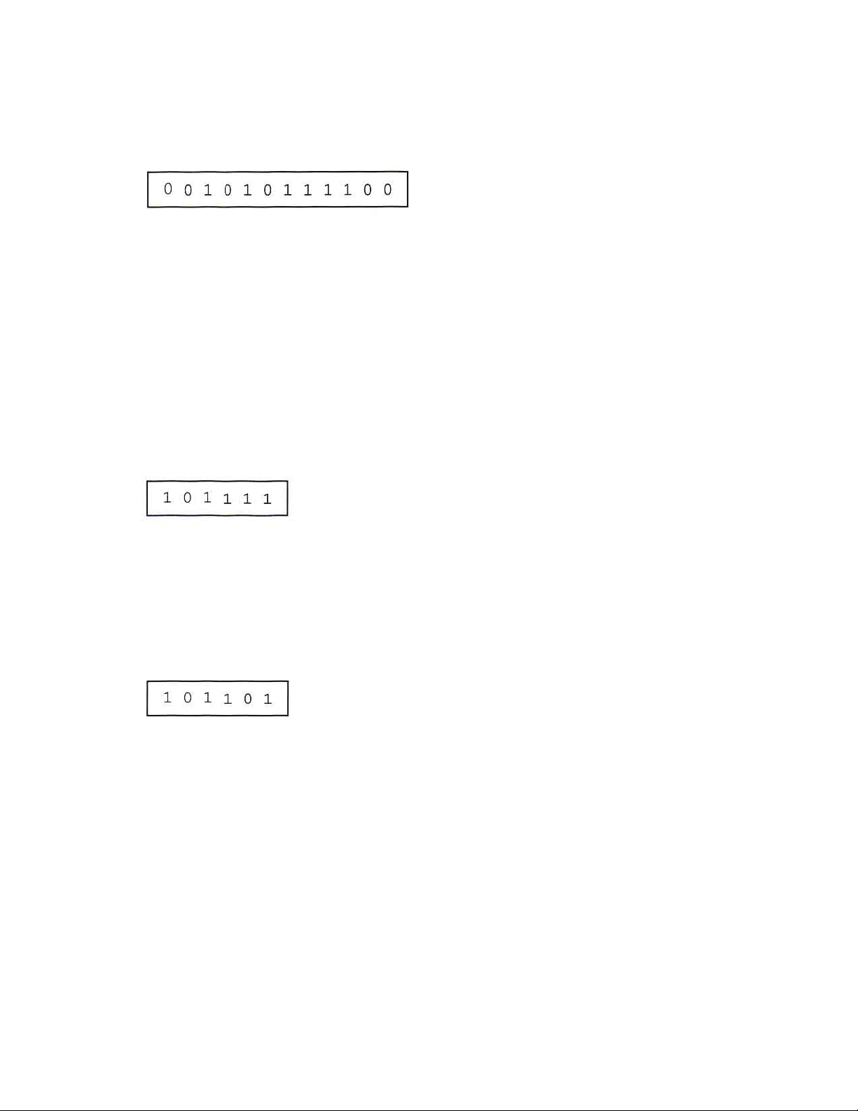
A) CHANNEL SELECTION - Channel selection is accomplished by properly setting the 12-position DIP
switches to the corresponding channel code. Channel codes can be selected from Figure #3 or the code
card attached to the Input Channel Select cover plate. Set the DIP switches from left to right.
For example - If channel 11 is selected, then its corresponding channel code is:
0 = Switch in DOWN Position
1 = Switch in UP Position
T o select an HRC input channel, utilize the HRC code chart attached to this manual.
CAUTION: Channel codes for input and output channel select are completely different.
B) BAND SELECTION - Band selection is accomplished by setting the 6-position DIP switches to the
corresponding band. Only three switches are used for this purpose. Band select codes can be chosen from
Figure #3 or the code card attached to the Input Channel Select cover plate. Then, set the DIP switches
from left to right. For example - If band A-3 to Channel 13 is desired, then its corresponding code is:
C) AFC SELECTION - Most off-air TV stations are usually very close to the specified carrier frequency such
that the AFC function need not be used. However, some UHF stations have a tendency to drift, so it is best
to utilize the AFC function. Simply set the AFC switch (fifth switch to the left of band select) to the down
position for automatic frequency control (AFC “ON”). For example - If AFC is desired on band A-3 to
Channel 13, then the set up is:
Off-cable processing should not require AFC, but make sure the proper code sheet (Standard Channel or HRC)
is utilized.
D) INPUT CONNECTION - After an input channel has been selected (Steps A through C), connect an antenna
or cable source to the RF input terminal. Any VHF , UHF or cable source can be connected to the RF input
connector. For optimum video quality response, the input signal level should have a minimum of +20dBmV.
This unit will function with input signal levels as low as -20dBmV but any signals below -20dBmV will be
squelched by the internal squelch circuit.
025-000232 REV C
Page 3
Page 4

3) DEMODULA TOR AGC ADJUSTMENT
A) The demodulator delayed AGC adjustment is factory set for a +5 to +10dBmV threshold. This setting
provides the best signal-to-noise ratio for low level off-air signals.
B ) For cable operation, where high-level adjacent channel signals may be present, adjacent channel
performance may be improved by lowering the AGC threshold level.
C) To adjust the delayed AGC threshold level for cable operation:
1. Connect a cable signal carrying three adjacent channels at a level of +20dBmV maximum to
the RF input connector.
2. Set the input channel select DIP switches to the channel located in the center carrier frequency
(of the three channels).
3. Adjust the demodulator delayed AGC control (R54) slightly for the least amount of adjacent
channel interference.
025-000232 REV C
Page 4
Page 5
025-000232 REV C
OTR-3550-SW
DEMODULA TOR ST ANDARD CHANNEL SELECT CHAR T
Page 5
Page 6
025-000232 REV C
Page 6
Page 7
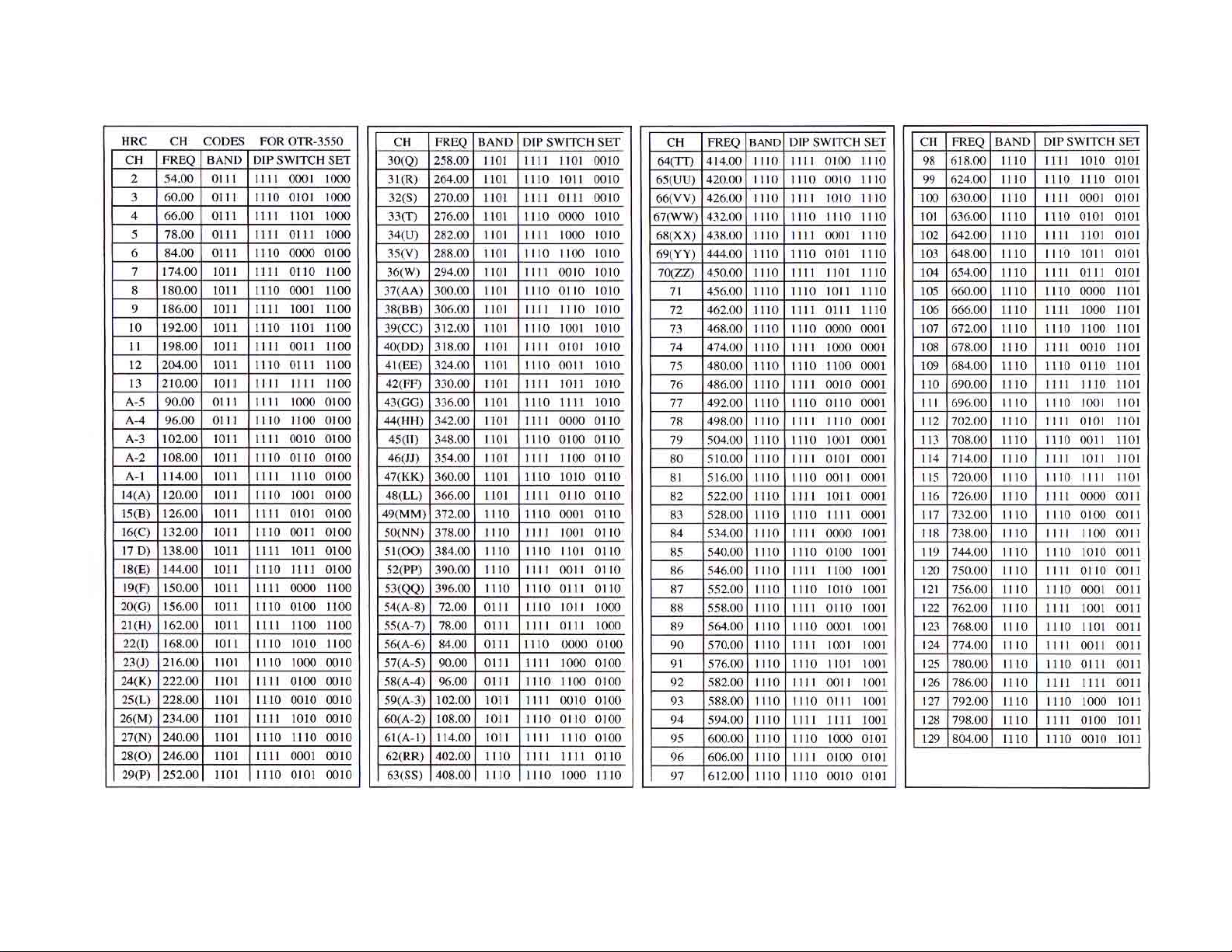
HRC CHANNELS
025-000232 REV C
Page 7
Page 8
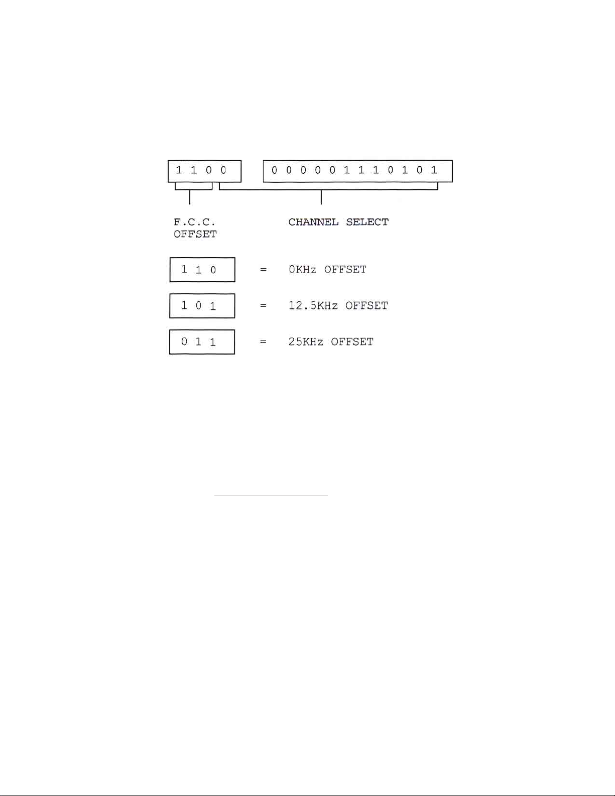
4) OUTPUT CHANNEL SELECTION - MODULA TOR
Remove the front panel plate marked “Output Channel Select” to expose the channel select and offset
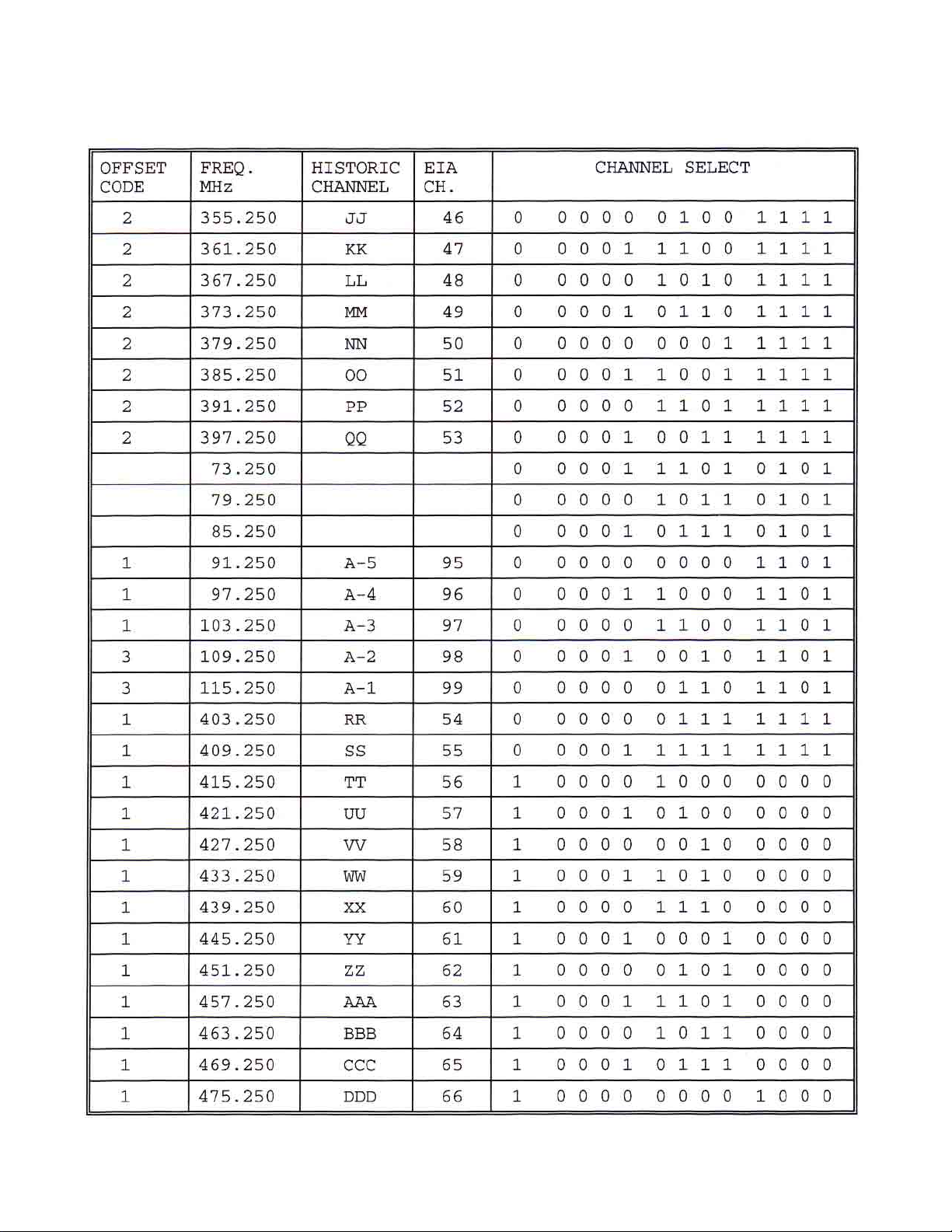
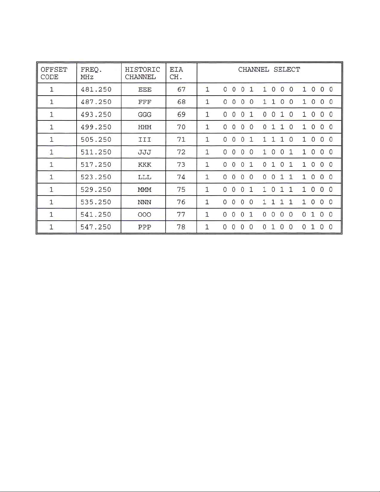
select DIP switches as shown in Figure #4. See page 1 1 for Modulator switch codes.
Figure #4
OUTPUT CHANNEL SELECT
A) Select the desired channel by use of the channel select switch and the code sheets.
2) Select the proper offset by use of the offset switch and the offset information below .
3) The example above indicates channel 6 with 0kHz offset.
Offset Select Information
1) Channels A, B, C, L to W, AA to EE & GG to QQ = 12.5KHz.
2) Channels A-2, A-1 & FF = 25KHz.
3) All others = 0KHz.
025-000232 REV C
Page 8
Page 9
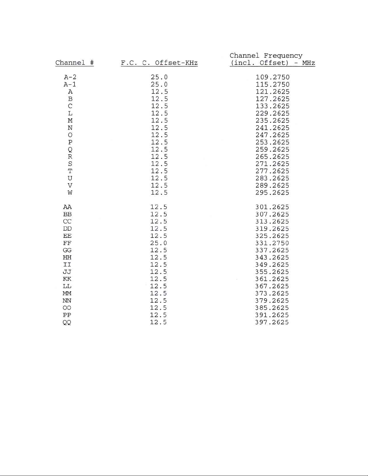
F .C.C. OFFSET FREQUENCIES
025-000232 REV C
Page 9
Page 10

5) VIDEO MODULA TION ADJUSTMENT
A) Connect a video source of approximately 1V p-p to the video input connector (75 ohms input Z) on the
rear panel. The video should be of a reasonably bright scene (commercials are usually excellent).
B) Rotate the video modulation level adjust control slowly clockwise until the video overmodulation LED just
turns on. The light may blink with differences in average picture level. CAUTION: If the modulation is set
too high, compression or lack of contrast will occur during high intensity scenes.
6) AUDIO MODULA TION ADJUSTMENT
A) Connect an audio source of 300mV p-p (minimum) to the balanced audio input connector (600 ohms
input Z) on the rear panel. The source should be typical of the program material to be carried.
B) Rotate the audio modulation level adjust control slowly clockwise until the audio overmodulation LED just
begins to blink. CAUTION: Overmodulation can result in severe distortion in some TV sets. Set this
control at peak program levels.
7) RF AND AURAL CARRIER LEVEL ADJUSTMENT
A) Using a field strength meter, set the video carrier to the desired level with the RF output level adjust control.
B) T une the field strength meter to the aural carrier (4.5MHz above the video carrier).
C) Adjust the aural carrier level control to the desired level, typically 15dB below the video carrier.
CAUTION: Reducing the visual/aural carrier ratio to less than 15dB can result in high out-of-band spurious signals in adjacent channels.
8) MISCELLANEOUS
A) The OTR-3550-SW is BTSC stereo compatible. It is shipped in the “mono” mode. To defeat
pre-emphasis, in order to use a composite BTSC baseband input signal, move the internal jumper plug
from W -9 to W -10. This plug is located in the left front area of the circuit board.
B ) If a scrambling unit is utilized with the OTR-3550-SW, follow the instructions associated with the
scrambler. The video I.F . output level is +40dBmV , and the audio carrier level is determined by the aural
carrier level adjustment - typically +17dBmV @ 15dB A/V ratio.
C) This unit is equipped with a 0.5A slo-blo fuse. For continued safety and to maintain proper performance of
the unit, please replace only with an equivalent fuse.
D) A -20dB test point (type F connector) is provided in the rear panel.
025-000232 REV C
Page 10
Page 11
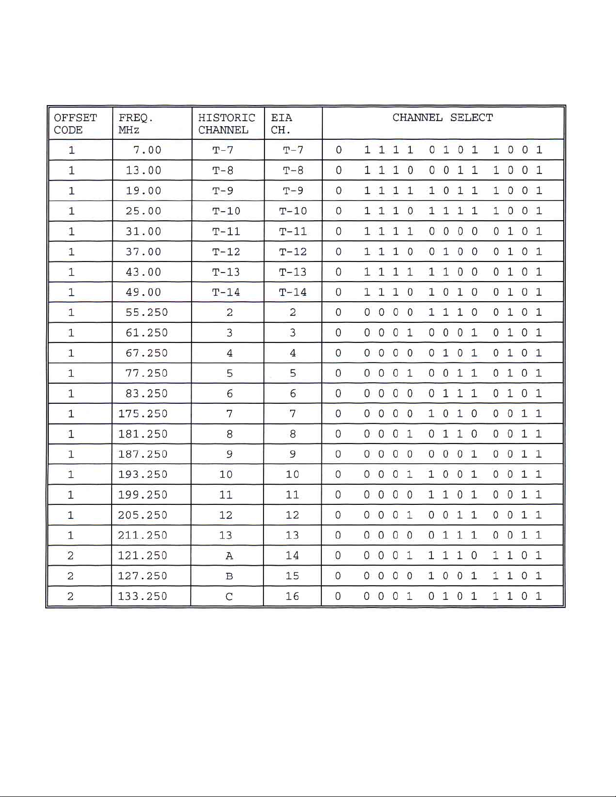
OTR-3550-SW
ST ANDARD TV CHANNEL - OUTPUT CODES
025-000232 REV C
Page 11
Page 12

OTR-3550-SW
ST ANDARD TV CHANNEL - OUTPUT CODES (Continued)
025-000232 REV C
Page 12
Page 13
OTR-3550-SW
ST ANDARD TV CHANNEL - OUTPUT CODES (Continued)
025-000232 REV C
Page 13
Page 14
OTR-3550-SW
ST ANDARD TV CHANNEL - OUTPUT CODES (Continued)
025-000232 REV C
Page 14
Page 15

OTR-3550-SW
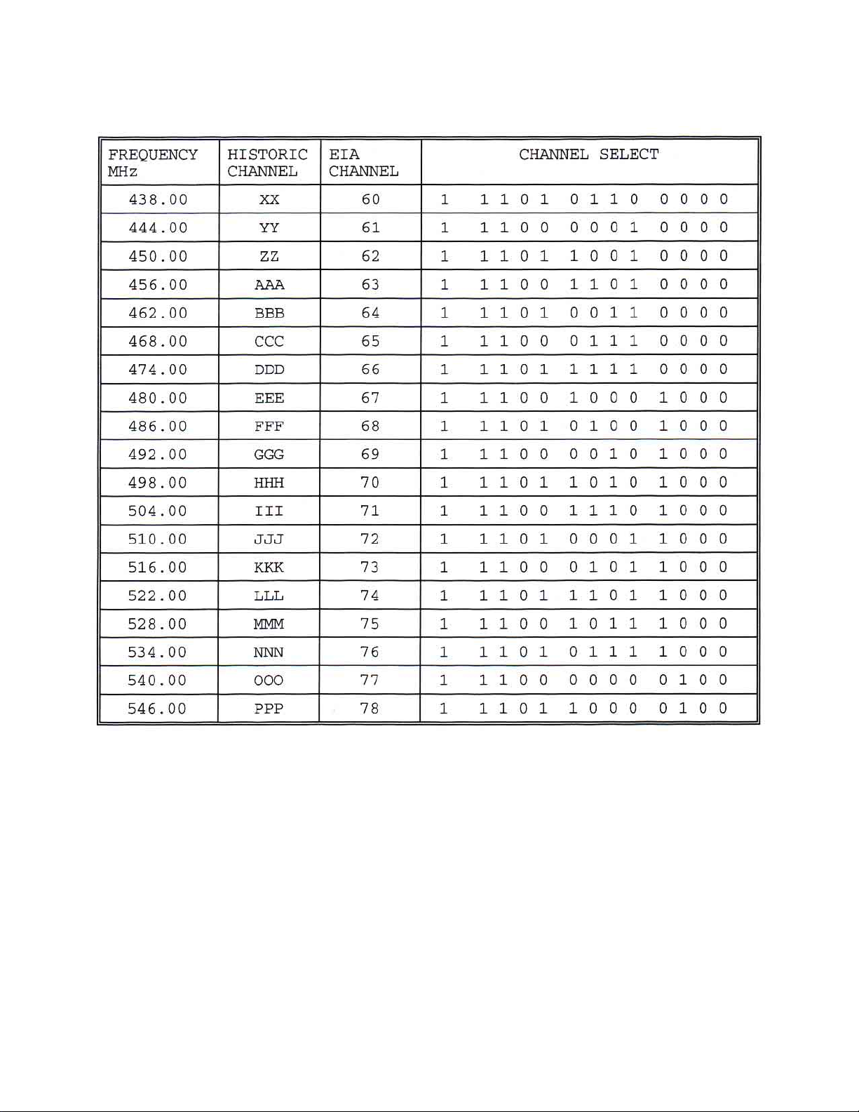
HRC TV CHANNELS - OUTPUT CODES
025-000232 REV C
Page 15
Page 16

OTR-3550-SW
HRC TV CHANNELS - OUTPUT CODES (Continued)
025-000232 REV C
Page 16
Page 17
OTR-3550-SW
HRC TV CHANNELS - OUTPUT CODES (Continued)
025-000232 REV C
Page 17
 Loading...