

Page 1

Rack Mount High-Power EDF A
Installation Guide
OTEA-CM Series
Optimized For Use with Direct Modulation 1550nm T ransmitters
025-000572 Rev 2 31 Mar 2009
Page 2

Notices
The information contained in this document is subject to change and revision without notice. Olson Technology, Inc. (OT) believes that the information provided is accurate and reliable, however OT makes no warranty of any kind as to the information contained in this document, including without limitation the implied warranties
of merchantability or fitness for a particular purpose. Further, OT does not assume
responsibility for use of the information contained in this document or for any infringement of patents or other rights of third parties that may result from its use. OT
shall not be liable for errors contained in this document or for incidental or consequential damages in connection with the furnishing, performance, or use of this material.
OT grants no license, directly or indirectly, under any patent or other intellectual
property rights from use of the information provided herein.
Copyright 2009 Olson Technology, Inc. All rights reserved. You may not reproduce,
transmit, store in a retrieval system, or adapt this publication, in any form or by any
means, without the prior written permission of OT, except as allowed under applicable copyright laws.
Preface
Please take time to read and understand this User’s Guide and familiarize yourself
with the information that we have compiled for you before you use the product. This
User’s Guide should stay with the product to provide you and all future users and
owners of the product with important operating, safety and other information.
Page 3

Table of Contents
1. PRODUCT FAMILIES........................................................1
KEY FEATURES................................................................................................1
OTEA RACK MOUNT DEVICES ........................................................................1
2. SAFETY INFORMATION................................................... 2
SAFETY CONVENTIONS....................................................................................2
LASER CLASSIFICATION IIIB > 100MW 1550NM...............................................3
DEVICE SAFETY LABELING...............................................................................4
GENERAL SAFETY INSTRUCTIONS....................................................................5
CONNECTOR CLEANING GUIDE........................................................................7
PROTECTING YOUR DEVICE FROM OPTICAL CONNECTOR DAMAGE................9
BACK REFLECTION PREVENTION ...................................................................10
3. ENVIRONMENT AND PRECAUTIONS.........................11
4. INSTALLATION PROCEDURE.......................................12
OVERVIEW.....................................................................................................12
THE FRONT PANEL OF THE UNIT....................................................................13
REAR PANEL OF THE UNIT .............................................................................15
RECOMMENDED INSTALLATION EQUIPM ENT..................................................16
MECHANICAL MOUNTING...............................................................................18
ELECTRICAL CONNECTIONS...........................................................................19
OPTICAL CONNECTIONS................................................................................21
INITIAL ELECTRICAL POWER-UP AND CONFIGURATION..................................26
ENABLING OPTICAL AM PLIFICATION...............................................................29
5. TROUBLESHOOTING.....................................................30
LED STATUS INDICATION...............................................................................33
RS-232 INTERFACE COMMANDS...................................................................34
RS-232 PROVISIONER COMMANDS...............................................................36
Page 4

1. Product Families
Olson Technology, Inc. manufactures high performance fiber amplifiers and lasers, modules and subsystems to meet the rapidly growing demands of the communication market.
OT’s wide range of high and low power amplifiers and lasers are compact, cost-effective
and exceptionally reliable.
OT’s product innovation stems in part from a concept known as parallel pumping which
enables fiber devices to generate almost unlimited power and provides for pumping redundancy, enhanced reliability and extended lifetime of devices.
The OTEA-CM series is specially optimized for used with Direct Modulation 1550nm
Transmitters.
Key F ea tures
• Long Life Time
• Specially Designed to Operate with Direct Modulation 1550nm Transmitters
• Low Noise Figure
• High Conversion Efficiency and Low Power Consumption
• Unique Saturated Output Power
• Compact Design
• Low PMD and PDL
OTEA Rac k Mount De vices
The OTEA devices are rack mount amplifiers designed for use in standard 19-inch equipment racks. They are complete with dual universal voltage/frequency power supplies for
redundancy. The unit is controlled through menu driven front pushbuttons with an LCD
display or a standard RS-232 interface.
1
Page 5
2. Safety Information
Safety Con v entions
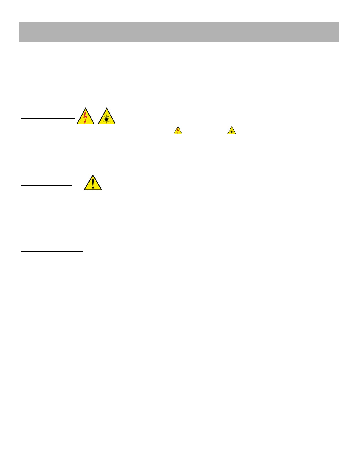
We use various words and symbols that are designed to call your attention to hazards or
important information. These include:
WARNING:
Refers to a potential personnel hazard. (
a procedure that, if not correctly followed, may result in bodily harm to you and/or
others. Do not proceed beyond the WARNING sign until you completely understand
and meet the required conditions.
Electrical) ( Laser radiation) It requires
CAUTION:
Refers to a potential product hazard. It requires a procedure that, if not correctly fol-
lowed, may result in damage or destruction to the product or components. Do not
proceed beyond the CAUTION sign until you completely understand and meet the
required conditions.
IMPORTANT
Refers to any information regarding the operation of the product. Please do not
overlook this information.
2
Page 6

Laser Classification IIIb > 100mW 1550nm
This device is classified as a high power Class IIIb laser instrument under 21 CFR
1040.10. This product emits invisible laser radiation at or around a wavelength of 1550 nm,
and the total light energy radiated from any optical output is greater than 100mW. This
level of light may cause damage to the eye and skin. Despite the radiation being invisible,
the beam may cause irreversible damage to the cornea. Laser safety eyewear is not provided with this instrument, but must be worn at all times while the laser is operational.
WARNING:
Use appropriate laser safety eyewear when operating this device. The selection of
appropriate laser safety eyewear requires the end user to accurately identify the
range of wavelengths emitted from this product. If the device is a tunable laser or
Raman product, it emits light over a range of wavelengths and the end user should
confirm the laser safety eyewear used protects against light emitted by the device
over its entire range of wavelengths.
WARNING:
Use of controls or adjustments or performance of procedures other than those set
forth in this User’s Guide may result in hazardous radiation exposure.
CAUTION:
Do not install or terminate fibers when amplifier is active.
3
Page 7
Device Saf ety Labeling
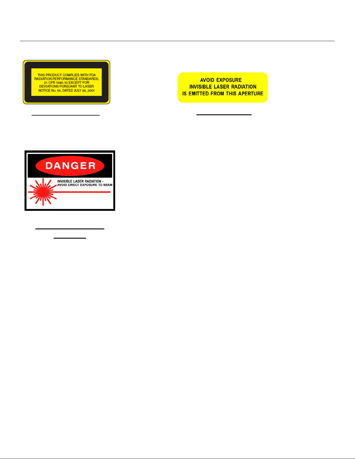
The figures below show the FDA, and other labels and their placement on the product.
Certification Label
MAXIMUM OUTPUT: 500mW
WAVELENGTHS: 1520-1625nm
CLASS IIIb LASER PRODUCT
Warning Logotype
Location
Top Cover or Front Panel
of Device.
Aperture Label
4
Page 8
General Safety Instructions
In order to ensure the safe operation and optimal performance of the product, please follow these warnings and cautions in addition to the other information contained elsewhere
in this document.
CAUTION:
Before supplying the power to the instrument, make sure the correct voltage is
used. Failure to use the correct voltage could cause damage to the instrument.
WARNING:
Make sure this instrument is properly grounded. Any interruption of the protective
grounding conductor from the protective earth terminal can result in personal injury.
WARNING:
This device and all parts or components thereof are not meant to be operator serviced, except for the replaceable fuse(s). Refer all servicing to qualified OT personnel. To prevent electrical shock, do not remove covers or system components. Any
tampering with or disassembly of the device, parts, or components will void the
warranty and possibly expose the operator to an electrical shock hazard.
WARNING:
DC powered instruments are not meant to be attached to a power source that is capable of delivering more than 30 Amps or connected to a circuit with a 30 Amp
breaker. Failure to limit the source current to less than 30 Amps can result in operator injury, voiding of the warranty and/or instrument damage.
WARNING:
Laser radiation is emitted from all optical outputs simultaneously. Avoid exposure
from all unused optical ports.
WARNING:
Do not enable the laser when no fiber or equivalent is attached to the optical output
connector.
5
Page 9

WARNING:
If this instrument is used in a manner not specified in this document, the protection
provided by the instrument may be impaired and the warranty will be voided. This
product must be used only in normal conditions.
6
Page 10
Connector Cleaning Guide
Optical fiber connectors require care and careful cleaning. Caps should be left on connectors whenever they are not in use. Do not touch the connector end. Damage to connector
end faces caused by improper care is not covered by the warranty.
Equipment
We have found the following equipment useful in maintaining connector
cleanliness:
Automatic connector cleaner (CLETOP
TM
) (available from most suppliers) or canned iso-
propyl alcohol with clean optical wipes and canned air.
Connector inspection microscope. (The Noyes 300-200 or 300-400 optical fiber scope is
good, as is the AMP fiber inspection scope and the Buehler fiber scope. Typical low cost
multimode connector viewers are not suitable for inspecting single-mode connectors).
Cleaning procedure
WARNING
After making sure that the light source is off (!!!), check the connector ferrule end using
the connector inspection microscope. If no dirt, grease or small particles are visible no further cleaning is necessary.
Use canned air to remove loose particles.
Use automatic connector cleaner such as CLETOP
Either
connector slightly. Using an automatic cleaner is our preferred technique. Note that some
low cost cleaners may leave small particles on the fiber surface.
directed on the box. Be careful with angled connectors (connectors with green
boots) to make sure the full surface contacts the cloth. You will need to tilt the
:
TM
. Wipe the connector as
Moisten a clean optical wipe with alcohol and wipe connector. Finish by wiping
Or
the connector with a dry part of the wipe. Be careful not to allow oil from fingers to
contact connector. Allow the connector to dry for 1 minute. Inadequate drying can
result in the alcohol residue burning into the connector end when the fiber is lit.
Inspect the connector ferule under the microscope. Clean again if necessary.
If a connector is to be used to transmit high powers (>50mW), great care should be taken
in cleaning. Mating loss of these connectors should be kept to a minimum.
7
Page 11

Bulkhead cleaning
Fiber bulkhead adapters contain a zirconia or phosphor-bronze sleeve. After removing the
connectors, these can be cleaned with a pipe cleaner moistened with isopropyl alcohol,
and dried with canned air.
Troubleshooting
A small black area appears in the middle of the connector which cannot be removed by
cleaning.
Some material (typically oil from skin contact, residue alcohol or particles from connector
cleaning devices) has burnt on the connector surface. Do not use your device and contract
OT for assistance.
A small circle of dried droplets are visible on the end of the connector.
The connectors were mated when one was still wet (typically from water/alcohol). Repeat
cleaning procedure.
The connector is clean but the loss on mating varies by 10dB or more.
Check to see if the bulkhead adapter sleeve is cracked. Be careful not to over-tighten connectors.
A gray powdery grime continues to appear on the connectors after repeated mating.
If the bulkhead adapter sleeve is made from phosphor-bronze, some of the metal is
probably rubbing off on the connectors.
8
Page 12

Protecting Your De vice from Optical Connector
Damage
Output powers of 1 Watt or less
CAUTION:
High optical powers can burn oil from fingerprints, dirt, dust or cleaning alcohol into
the connector ends. The resulting damage looks like a black dot in the middle of the
connector end-face and is clearly visible under a connector viewer microscope. If
you are using an amplifier for component testing, we recommend following the
"Connector cleaning guide" section (above).
If connectors are being frequently connected and disconnected, occasional connector contamination is likely. Large numbers of connector mating are common in a manufacturing
setting where hundreds of parts are being power tested.
9
Page 13

Back R eflection Prev ention
CAUTION:
Back reflection into the amplifier or laser can degrade the device performance or
cause failure. The device is designed to accommodate normal back reflections exhibited from use with fiber spans.
For outputs with standard fiber connectors, examples of normal back reflection are
as follows. Expected back reflection for FC/PC connectors is -14dB. Expected back
reflection for FC/APC is -40dB. Proper cleaning of the connectors is an essential
process for successful use of the device. We recommend following the attached
"Connector cleaning guide".
For bare fiber outputs, the expected back reflection with a flat cleave is -14dB. A
random break or crushed fiber may have any back reflection from -14dB and lower.
A good splice to a similar fiber has a back reflection around -60 dB. It is essential to
have a quality cleave and fusion splice by a trained in dividual to minimize the risk of
inducing excessive back reflection. Splicing the bare fiber output to a dissimilar fiber can cause excessive back reflection and will void the warranty. Contact the
manufacturer if this process is required. If the bare fiber will be powered up without
being spliced to another fiber, make sure the surface of the fiber is of good quality
and clean. Check the quality of the cleave at a low output power using an infrared
visualizer and increase the output power.
Optical damage may result from failure to comply with the above instructions. Such
damage is not covered by the warranty.
10
Page 14

3. Environment and Precautions
WARNING:
Always use your device in conjunction with properly grounded power source.
CAUTION:
Do not expose the device to a high moisture environment.
CAUTION:
The amplifier has protection against a low optical input signal and the unit will shut
down if the input signal is removed. We recommend the amplifier not be used without an optical input signal. OT will not be responsible for the damage sustained by
the device resulting from a lack of input signal.
CAUTION:
Avoid unnecessary back reflections into the amplifier otherwise the device may be
destroyed. Use caution when connecting the amplifier to an external fiber line.
Strong non-linear effects may turn a significant portion of optical power into the
amplifier.
CAUTION:
Wait at least 2 minutes after switching on the device before enabling maximum
emission.
CAUTION:
Always clean optical connectors before connecting them to the amplifier. Use only
the type of connectors noted in the specification. Use special high precision adapters for connecting the amplifier to an input source, otherwise maximum polarization
extinction ratio may not be achieved. OT will not be responsible for any damage
sustained by the device as a result of using dirty or incompatible connectors.
11
Page 15

4. Installation Procedure
Overview
This guide is intended to aid a technician or operator in the field with installation and troubleshooting during the installation process. The troubleshooting section is intended to help
determine the cause of any fault, whether it be with the EDFA or some other component in
the network and to determine whether the failure is caused by some configuration error or
faulty connection to the EDFA. Although the technicians may be well versed in troubleshooting techniques, they may not be aware of the specific features of the OT EDFA that
can aide in this process.
Specific installation procedures are also found in the operations manual. However, this
guide covers installation and troubleshooting in more detail in an effort to aid the installer
further and for additional reference as needed.
It is assumed the technician is properly trained to handle fiber optics and laser class IIIb
optical equipment.
12
Page 16

The Front Panel of the Unit
The actual appearance of the front panel is determined by the specific model of the EDFA.
1. Laser emission key-switch
2. 10/100BaseT LAN (Ethernet) port for SNMP and other TCP/IP communication
protocols.
3. RS-232 serial craft port interface.
4. (Optional) LCD menu selection buttons.
5. Low power mode button.
6. Alarm state indication LED’s.
Green = no alarm
Yellow = minor alarm
Red = major alarm.
i. 48V SUP = 48V electrical power supply status
ii. PWR IN = Optical (1550nm) input power status
iii. PUMP = Internal laser pump diodes status
iv. MODE = Equipment mode status
v. EQUIP = Equipment overall status
vi. PWR OUT = Optical (1550nm) output power status
vii. FANS = Equipment fan status
7. (Optional) LCD display.
13
Page 17

8. Front air intake opening. Cover guard is removable with thumb screw to allow
access to filter material for service/ replacement.
9. Grounding point.
10. Optical (1550nm) output monitor port.
11. Fiber tray with thumb release screws for internal optical connector ac-
cess/servicing.
12. Optical (1550nm) input port.
14
Page 18

Rear P anel of the Unit
1. Case grounding points.
2. Expansion panel for future use.
3. Removable power supply card with thumb screws
4. Power supply card status LED
a. GREEN LED indicates normal operation.
b. No illumination of LED indicates power failure.
5. Fuse holders
6. Fan shroud with securing screws
7. Fans (air flow through front of unit and out through fans at rear of unit)
8. RJ45 socket with alarm relay connections.
9. Electrical signaling terminal strip
a. DET1, DET2, SIG1, SIG2 for future use
b. INT, INT are interlock terminals. They should be electrically shorted to-
gether to enable operation of the unit. They may be wired to an external
interlock switch if required.
10. External power supply terminal strip
a. RTN (A), -48V (A), RTN (B), -48V (B) for redundant external -48V return
and supply.
15
Page 19

Recommended Installa tion Equipment
The following is a list of suggested equipment to aide installation and troubleshooting, it
may not be complete due to unique requirements at different locations.
1. Handheld Optical Power Meter with specifications:
• Capable of handling up to +23dBm at 1550nm. (Verify power requirement
against optical output power specification for the device being installed)
• Most power meters have wavelength selection, but solely for correct calibrated
reading not to actively filter out that wavelength range. That means that if both
video (1550nm) and data (1310/1490nm) are both being transmitted down the
same fiber the meter will display the composite power level. There are newer
more advanced optical power meter types that include wavelength specific filters for use in diagnostic of optical CATV systems to avoid this issue. These
meters can help simplify power measurements but are not strictly required.
2. Optical connector end-face inspection scope with angled and flat adapters for the
connectors used on the amplifier device (typically SC, but check the specification
document for connector types used). It is recommended that a non-direct viewer is
used so that the end face is not directly observed by eye, instead by a digital sensor.
3. Optical fiber end-face cleaning supplies (isopropyl alcohol, lint free optical wipes,
cleaning cartridges (such as a CLETOP
TM
)).
4. Laptop with Ethernet and RS-232 Serial port communication capabilities and serial
terminal software (such as “HyperTerm”).
5. RS-232 serial cable(s) - mating type and straight/cross-over determines if serial
communication can occur. See specification manual for pin out of device serial
port.
6. Multiple SMF-28 fiber patch cords (with 3mm buffering preferable) of types:
• SC/APC to SC/UPC
• SC/APC to SC/APC
• SC/UPC to FC/PC*
• SC/APC to FC/PC*
* FC/PC is a common connector type on optical test equipment and instruments
such as optical power meters and optical spectrum analyzers.
16
Page 20

7. Optical connector adapters, allowing mating of the various optical patch cords
above.
8. Ethernet cables and hub/switch to allow device to be accessed via SNMP.
9. Variable Optical Attenuator (VOA) - useful for optical diagnostics.
10. An OSA (Optical Spectrum Analyzer) is not normally required but helpful in isolating some optical issues.
11. Mechanical mounting equipment - Screw drivers, bolts, etc.
12. Electrical installation equipment - multimeter, electrical power cabling, electrical cable termination tools, etc.
17
Page 21

Mechanical Mounting
1. Determine mounting location:
a. The unit will fit in a standard 2RU 19-inch rack space with the use of the (sup-
plied) 19” mounting brackets.
b. The fans in the device direct airflow through the intake filter on the unit front
panel and expel air from the fans at the rear. Allow enough clearance around
the front filter and rear fans for good airflow. Do not allow foreign objects into
any of the air ducts and do not block them with electrical or optical cables.
c. Caution
: Take care during installation not to damage the unit. Special attention should be given to the optical connector adapters on the front panel and
electrical terminals on the rear panel.
2. There are two 19” mounting brackets with mounting screws supplied. If the brackets
are not already attached to the unit they should be first bolted to the unit before installation in the rack.
3. One of the mechanical features of the EDFA is the fiber trays in the front of the unit.
These trays allow for the installer or maintenance person to access and unplug the
internal fiber connector from the optical connector adapters for inspection and cleaning. Before relocating the unit to the rack, make sure that the trays are secured in the
closed position via their thumb screws.
4. Mount the EDFA to the rack using the screws required by the equipment rack at the
installation site. See the unit’s specification document for weight and dimensions.
5. Once the unit is mounted, make sure the laser emission key-switch on the front
panel is in the off position. The next step is to hook up the electrical wiring as specified in the next section.
18
Page 22

Electrical Connections
1. Caution: Ensure the laser emission key-switch is in the off position (or removed)
before electrical turn-up.
2. Information on the electrical systems of the unit:
a. The unit has two power supply cards which are accessible from the rear panel.
These power supplies are redundant, so a single failure will allow the unit to
continue its operation but with appropriate warning alarms. The power supply
cards are also hot swappable. There is no electrical power switch for the unit.
Removing both power supply cards at the same time will power down the unit.
It is suggested that the cards remain plugged in during the installation and that
the power feeds be switched off until ready to turn unit on for the first time.
b. There is a laser emission key-switch on the front panel that turns the output
optical power of the unit off/on. This should always remain in the off position
for laser safety until the unit is completely hooked up and ready for testing. Be
certain it is in the off position at this time.
c. There are fuse holders on the rear panel of the unit. Ensure they contain the
correct rated fuse (see specification document for the unit). These should only
require access during normal operation to replace a blown fuse.
3. The two Interlock electrical terminals on rear panel (both marked INT) require shorting together for the EDFA to operate normally. This interlock feature is provided for
laser safety purposes as required by certain installations e.g. for an external laser interlock switch on a cabinet or room door.
4. Electrical power connections. In this step the external electrical power supply(s) will
be connected to the terminal strip on the rear of the unit. It should be noted that if the
electrical supply is on then the unit will immediately power up as soon as the first circuit is completed.
a. Always connect the ground terminal cabling to the unit first (and during any un-
install of the unit remove them last).
b. Next connect the -48VDC and supply return terminals to the external power
supply. See the specification document for the unit’s current requirement. Use
the correct gauge wire for the current requirement and the correct buffering
material for the supply voltage.
5. To take full advantage of the power supply card redundancy it is advised that two different external power sources are used.
19
Page 23

6. The unit should be powered up at this point. The fans will be spinning and front
panel LED’s will be illuminated. The power supply LED’s on the rear of the unit
should both be green. The laser emission key-switch should remain in the off position.
7. If the unit will be connected to a wired network LAN then the Ethernet cable should
be connected to the Ethernet port on the front of unit at this time and routed to an
appropriate networking hub or switch.
8. If required an RS-232 cable may be connected to the serial port on the front panel of
the unit.
a. The RS-232 interface has been set to the following parameters: 9600 Baud, 8
data bits, 1 stop bit, no parity and no flow control.
b. A three wire (RxD, TxD, GND) interface is used. In addition, the interface cable
must have the proper connector on each end. Cables typically have 9 pins
(DB-9) or 25 pins (DB-25) with ‘male’ pins or ‘female’ receptacles inside the
connector shell. The RS-232 connector on the front panel of the Laser Driver
is a 9 pin (DB-9) female connector. Therefore the users’ interface cable must
have a 9 pin male (DB-9) connector on one end to connect to the laser driver.
The other end of this cable needs to match the computers’ interface connector. Remember that this cable must be wired in a straight-through configuration. Therefore, on a computer connection with a 9-pin DB-9 connector Pin 2
would connect to Pin 2, Pin 3 to Pin 3 and Pin 5 to Pin 5.
20
Page 24

Optical Connections
1. Installer Must Be Trained in (Class IIIb) Laser Safety.
2. Prior to connecting any fibers to the EDFA a quick review on fiber handling and how
it relates to potential problems and more importantly safety are in order:
c. Review the optical safety guidelines at the start of this guide.
d. The EDFA’s covered in this guide are assumed to be class IIIb as described in
IEC 60825-1.2 Standards. Although there are several factors that influence the
class rating, the optical output power level is the main factor and is what ultimately may cause harm if appropriate precautions are not followed.
e. A few precautions are listed below but should not be used in place of full train-
ing;
i. Do not examine or look directly into broken, severed, or disconnected
optical fibers or cables. This includes optical connectors where there is
no dust-cap in place.
ii. Do not crush, compress, bend excessively, walk on or have over 10-lbs
of cable weight placed on external optical cables (that have a minimum
of 3mm protective buffering).
iii. If there are optical connectors where dust-caps have been removed and
no fiber connected, it is important to place dust caps on these connectors immediately. If power is off it is still important to keep dust off the
connector.
iv. Do not touch the optical connector end-face.
v. Dirty optical connectors can result in permanent damage to the fiber
end-face once optical power is applied. In these cases of optical damage, cleaning will not remove the burnt-on matter and the optical output
power will be reduced. The connector will require replacement to operate at nominal performance.
vi. It is the installer’s responsibility to be sure all connections are clean be-
fore applying optical power (i.e. enabling laser emission).
vii. Dirt includes oil from an accidental quick touch of a finger tip, or dirt from
the air after exposure for even a short length of time.
viii. Cleaning of the fiber end-face while optical output power is being emit-
ted will also cause burn damage to the end-face and should be avoided.
21
Page 25

ix. Optical connectors can also have pits and cracks in them from mechani-
cal mistreatment or by mating connectors that have dirt/contaminants on
the end-face(s). Cracks or pitting in the central location of the fiber endface reduce optical output power and, the connector will require replacement to operate at nominal performance. Dirt that gets into the pits
and cracks will remain and the connector will need to be replaced.
3. Optical Inspection and cleaning of fiber connector end-faces:
a. Warning: Make sure the laser emission key-switch is in the off position
b. The optical connector adapters of the unit have built in, spring loaded, shut-
ters. Not only do these shutters help prevent exposure to laser light, they also
help prevent contamination by airborne dirt to the internal connector optical
end-faces. In addition the internal optical connector end-faces are inspected
and cleaned at the factory before shipping. If any of the optical connector
adapters are missing external shutters then it is important to replace the
adapters as soon as possible with shuttered compatibles. A short term solution
is place a dust-cap on the adapter if not in use.
c. Any external optical cable to be connected to an adapter on the unit should
first be inspected just before connecting (but first ensuring it is not transmitting
unsafe optical power levels). It is also advisable to inspect the internal connector end face at this time. If a dirty fiber end-face is mated with a (clean) one
then typically both will become contaminated. In addition both could be damaged if optical power is restored.
d. Cleaning procedure for optical fiber connectors and adapters
i. Connector End-face Cleaning Methods (after cleaning re-inspect)
1. Preferred Method: Using a cleaning cartridge such as a
CLETOP
TM
device; wipe the connector end-face as directed on
the device. Be careful when cleaning angled optical connectors
(typically marked with a green boot) to make sure the end-face is
in full contact with the cleaning cloth - which may require you to tilt
the optical connector slightly.
2. Moisten a clean, lint free, optical wipe with alcohol and wipe connector. Finish by wiping the connector with a dry part of the wipe.
Over use of cleaning alcohol and/or inadequate drying can result
in the alcohol residue on the fiber end-face. Inspect after cleaning
for liquid drying patterns – if they exist then connector must be
cleaned further to remove them.
3. Use canned air to remove loose particles.
22
Page 26

ii. Internal optical connectors of the unit may also be inspected and
cleaned. The trays which house the connectors can be slid part way out
after loosening the thumb screws. The internal connectors are plugged
into the optical connector adapters and can be pulled out from the rear.
Gently pull out the adapter, by the body of the connector (never the fiber
or the boot) that needs inspection or cleaning. It can then be cleaned by
the normal cleaning procedures. Be sure to correctly re-mate the optical
connectors to the adapters.
e. Description of EDFA optical connector types.
Depending on which unit type is to be installed there may be one or more optical connector types to address, the actual connector types may differ from the
ones detailed here due to specific customization of the units at the customers
request:
i. The regular (non-CWDM) version of the multi-port EDFA uses SC/APC
(green/angled) optical connectors exclusively.
ii. The CWDM version of the multi-port EDFA uses both SC/APC
(green/angled) and SC/UPC (blue/flat) optical connectors.
iii. The APC stands for Angled Polished Connector which has an optical
end-face cut/polished to be 8
O
with respect to the direction of the fiber.
The connector bodies are typically green in color.
iv. The (U)PC stands for (Ultra)-Polished Connector which has an optical
end face cut/polished to be 90
O
with respect to the direction of the fiber.
The connector bodies are typically blue or black in color.
v. The blue and green are visual aids to remind end user that the two types
are different.
vi. Caution:
Do not mate an angled (APC) connector with a flat (UPC or
PC) connector. This can cause mechanical damage to both connectors
and does not provide correct low loss optical mating. At a minimum
there will be an “air gap” between the two connector end-faces causing
large attenuation (loss) of the optical power. It can also cause damage to
connectors by scratching or cracking the flat connector with the tip of the
angled connector. It is acceptable to mate a flat Polished (PC) and ultrapolished (UPC) connector since the difference is related to manufacturing quality, not physical end-face angle. However, to minimize optical attenuation it is advisable to not use the lower grade (PC) connectors.
vii. All the connector types (e.g. SC, FC, LC, E2000) have some kind of
alignment key or pin, which only allows one orientation for connector-toadapter mating, however this does not prevent mixing of angle and flat
connector types.
23
Page 27

viii. Caution: Ensure a correct mate between optical connectors - It is out-
side the scope of this manual to cover all the details of optical connector
and adapter types and how to actually align and ensure correct mate.
This should be covered in the operators/field engineers’ optical training.
More information on connector and adapter types and their use may be
found from manufacturers such as e.g. Molex, Huber Suhner, Seiko,
ADC.
4. Connecting external optical cables to the unit.
i. Caution
: Clean and inspect all optical connectors (internal and external) as
detailed above and follow laser safety procedures.
ii. For CWDM EDFA Models
hookup but if the unit is a CWDM model then it is suggested to hook up the
Voice/Data ports first (OS ports). These are designated by blue or black optical connector adapters housing the internal SC/UPC blue or black optical
connectors.
i. The CWDM ports (OS Ports) are for routing the Voice and Data digital
optical signals carried upstream and downstream (bi-directional) on
1310nm (O-Band) and 1490nm (S-Band) optical wavelengths respectively. These signals are multiplexed with the 1550nm (C-band) optically
amplified output video signal from the corresponding OSC port (angled/Green connector) The OS to OSC port multiplexing is passive and
the Voice/Data routing/communication should be independent of the operational state of the EDFA unit.
ii. Connect SC/UPC jumpers between the required CWDM OS port and
the installation sites voice/data equipment. Caution:
mate angled connectors to these OS CWDM ports.
. There is no specific order to initial optical
Do not attempt to
iii. That the voice/data does not rely on any electronics in the EDFA means
that some testing can take place immediately after hooking up the data
before powering up the EDFA and before the Video hookup. With EDFA
optical amplification disabled (laser emission key-switch off) the OS to
OSC port loss for 1310nm and 1490nm can be easily checked/verified
for optical continuity and loss. See the specification document for maximum specified loss at these wavelengths.
iv. Next connect the Output OSC ports (SC/APC/Green) to the installation
site downstream fibers (to the premise).
v. At this stage the data/voice service could be tested as there should be
optical continuity from instillations sites voice/data equipment to the
premises. The advantage of checking at this stage is that it is easier to
24
Page 28

isolate any problems of the deployment that are not related to video
equipment and/or the EDFA’s active optical performance.
iii. For non-CWDM EDFA models
i. Next connect the Output C ports (SC/APC/Green) to the installation site
downstream fibers (to the premise).
iv. For all EDFA Models:
Once all CWDM and output port connections have
been made then:
i. Connect the installation sites 1550nm (C-Band) video feed to the
(SC/APC/Green) Input C port of the EDFA unit.
ii. (Optionally) Connect monitoring equipment (power meter, CATV detec-
tor) to the 1550nm (C-Band) amplifier output monitor port of the EDFA
unit. See specification document for monitor port output power (typically
much lower output power level than the main output ports).
v. Proceed to next section
25
Page 29

Initial Electrical Po wer-Up and Configuration
1. Installer Must Be Trained in (Class IIIb) Laser Safety.
2. Caution:
Ensure the laser emission key-switch is in the off position (or removed) be-
fore electrical turn-up.
3. Electrical turn Up:
a. Enable -48V
above)
b. Ensure the power supply cards are fully inserted in the rear of the unit.
c. Front panel LED’s will go through initial illumination cycle of indication colors
(allow 10 seconds)
d. Front panel LED’s will indicate unit status after power up cycle.
e. Allow 1-2 minutes for LAN/SNMP service to be active after initial power up.
f. If the optical video input signal is at the correct operating level the Input Power
LED on the front panel should be green. (see LED troubleshooting table be-
low)
electrical power to the unit. (see electrical connections section
DC
4. Communicating over RS-232 to units craft port.
a. Ensure correct serial cable pin out and gender is used and both ends are fully
mated on the unit and the PC.
b. Any serial communication “terminal” software may be used. “HyperTerm” is
one such program.
c. Key settings to be aware of for communication is as follows:
i. Serial Port - The port number of the PC where the serial cable is con-
nected.
ii. 9600 Baud
iii. No Flow Control
iv. 8 bits data
v. Parity None
vi. Stop Bits 1.
26
Page 30

d. Recommended Additional settings:
i. Echo Typed Character Locally
ii. Send line Ends with Line Feeds
iii. Append Line Feeds to Incoming Line Ends.
e. If the terminal software is correctly set up then the unit will respond with a
prompt
>
if the <Enter> key is pressed on the PC.
f. Consult the Operations manual for full list of applicable serial commands.
g. Example:
Checking optical input power level via serial terminal software:
i. Enter the text:
RIP<Enter>
ii. The unit will respond with text similar to:
>Input Power = 6.2 dBm
Which in this case reports that the input power is 6.2 dBm (4.2 mW).
h. It is important to correctly configure the TCP/IP settings of the unit, via the se-
rial interface, for correct operation on the installation site LAN for SNMP com-
munication.
i. Login to gain access to provisioning commands:
LOGIN 999999<Enter>
where 999999 is the default login password, actual password may have
been changed by operators. Note: if you do not login then you can still
read settings but will not be able to change/write provisioning settings.
ii. Set fixed TCP/IP address of unit
SIP xxx.xxx.xxx.xxx<Enter>
where xxx.xxx.xxx.xxx is the fixed TCP/IP address that has been designated for this unit at this installation site.
iii. Set the TCP/IP Gateway address that the unit may use
SGATE yyy.yyy.yyy.yyy.yyy<Enter>
where yyy.yyy.yyy.yyy.yyy is the fixed TCP/IP address that has been
designated as the gateway for the unit at this installation site.
iv. Set the TCP/IP subnet mask the unit
SNET zzz.zzz.zzz.zzz <Enter>
where zzz.zzz.zzz.zzz is the TCP/IP sub-net mask that has been designated for the unit at this installation site.
27
Page 31

v. The present IP settings can be reported using the commands GIP,
GNET, GGATE.
i. Verify output power settings
i. To verify the per-port output power set-point
RPS<Enter>
This will return the set-point of the per-port output power.
ii. If the set-point is not correct use the command
SOP xx.x<Enter>
to change the output power set-point where xx.x is the desired per-port
power in units of dBm. See the unit specifications for the allowable perport output power range that is user settable.
iii. To verify the actual per-port output power use the command
ROP<Enter>
which will return the per-port output power as measured by the unit’s internal power monitor.
iv. Note
: If the laser emission key-switch is off or the unit is in major alarm
then the EDFA will emit amplified optical power so the actual measured
optical output power (reported by the ROP command) will be very low
and not in agreement with the user output power set point (reported by
RPS). This is normal; once the amplifier/laser emission is enabled, the
two values will be in agreement.
v. Note
: The amplifier output ports are passively split and have an associate range of output powers. See Test Data provided with shipping docs
for measured port-to-port power variation.
vi. Note
: The maximum user settable per-port optical output power is reported in dBm by using the command
RMP<Enter>
5. With the above items completed the EDFA may be activated by enabling laser
emission.
28
Page 32

Enabling Optical Amplification
1. Enable the EDFA optical operation by turning the laser emission key-switch to
the ON position. Allow 10 seconds for the unit to reach steady state. The Mode
LED light should turn Green and Output Power LED should turn Green.
2. Use the ROP command to read monitored per-port optical output power.
3. With the EDFA active the input ~1550nm should now be amplified to the premise locations and associated testing can be performed.
4. Note
: The optical output monitor port may be used to check ~1550nm service,
5. Further adjustment of the per-port output power may be made while the EDFA is active (using the SOP command) to maximize quality of service.
6. Note
: With the EDFA inactive (laser emission key-switch off or major alarm state in
the unit) there is no ~1550nm amplified signal emitted from the output ports or monitor port.
7. Note
: Turning the laser emission key-switch to the OFF position will cause an output
alarm and an equipment alarm condition on the unit. That is normal.
8. Note
: With CWDM models the signal power of ~1310nm and ~1490 data through
the OS and OC ports is not affected by laser enable state.
29
Page 33

5. T roubleshooting
1. Troubleshooting personnel must be trained in (Class IIIb) laser safety.
2. Caution: follow laser safety procedures at all times.
3. Caution: follow correct fiber handling and cleaning procedures (see above).
4. NOTE
: It can not be stressed enough that the most common causes of equipment
alarm, or poor quality of service is due to incorrect optical fiber connector mating and
poor optical fiber connector end face cleanliness. In general whenever a problem is
located at a specific port, the Technician should first verify that the connection type is
correct for that mate location and that both fiber end-faces of the mate are clean.
5. Electrical issues:
a. If no LED illumination on front panel of unit:
i. Check polarity and voltage of external power supply to rear panel elec-
trical power terminal strip
ii. Check power supply cards are installed correctly
iii. Check fuses for continuity
b. -48V status LED in major or minor state
i. If unit is operating but one of the power supply cards does not have
green status LED illumination
1. Check power supply card for physical damage/replace power
supply card.
2. Check that the power supply card is completely inserted.
ii. If Unit is operating and both of the power supply cards have illuminated
green status LED’s.
1. Check fuses for continuity.
c. Fan alarm in major or minor state
i. This indicates that one or more of the fans mounted to the rear of the
unit are not operating within specified rotational speed range.
ii. Replace any fans that are stopped or rotating slowly or making abnor-
mally loud operating noise.
30
Page 34

iii. Also If the unit has been in operation prior to the current alarm condition
inspect service (replace) the air filter material on the front panel of the
unit to prevent restriction of air flow due to dust build up.
iv. Ensure no air vents or ducts or fans are blocked or obscured by foreign
objects, optical or electrical cables.
v. To replace any of the Fan(s) (unit may remain powered):
1. Remove the screws securing the fan shroud.
2. Disconnect the electrical connectors to the fan(s) to be replaced.
3. Remove the screws securing the fan(s) to be replaced.
4. Remove and replace the fan(s) with the appropriate part(s).
5. Reverse steps 1-3 to reassemble.
6. Optical Issues
a. Input Power LED in major/minor alarm.
i. Ensure input ~ 1550nm signal power and wavelength are with the speci-
fications provided for the unit.
ii. Use RIP command to verify if monitored input power of the unit agrees
with power measured by external optical power meter.
1. If there is a power reading difference then ensure the optical fiber
2. Check for fiber and connector damage.
b. Video Service Quality issues.
i. Measure the optical output power of the optical output port(s) with is-
sues. Check that they are at correct operating level for the installation.
end-faces of the supply fiber and internal input connector of the
unit are clean and correctly mated.
ii. Use ROP command to verify if monitored output power of the unit agrees
with output power measured by external optical power meter.
iii. Ensure that low power mode has not been selected. Use Low power
button on front panel to toggle low power/normal operation (hold for
approx. 3 seconds to change state, allow 10 seconds for state change to
occur after button release).
31
Page 35

iv. Use local Video diagnostic equipment to confirm quality of input video
overlay optical signal.
v. Use local Video diagnostic equipment to confirm quality of amplified
video overlay optical signal using the monitor port of the unit.
vi. Increase optical output power of the unit (affects all ports) to boost sig-
nal to overcome loss.
vii. Decrease the optical output power of the unit (affects all ports) to reduce
the detrimental effects of SBS. (Quality of SBS suppression is determined by the optical CATV video transmitter that is input to the EDFA
unit)
viii. If Input optical power and wavelength in specification and optical output
is enabled and the unit is not in low power mode yet there is an output
power minor or major alarm or pump diode minor or major alarm it may
indicate internal failure of the unit.
c. 1310/1490nm Voice/Data Service issues (CWDM units only)
i. If there are issues with 1310nm/1490nm Voice/Data CWDM ports then
check the loss of the OSC-OS port routings with the EDFA disabled. If
the loss is
32
Page 36

LED Status Indica tion
1. LED Status Table
LED Color Alarm Other Indication Condition
All LED’s Green None Data or Voice failure but Video
OK
All LED’s Green None Weak or no video signal to entire
neighborhood fed off that port
48V Sup Red Major no other LED’s affected Blown Fuse
48V Sup Amber Minor no other LED’s affected 48V Power Supply Feed Missing
48V Sup Green None - -
Equip Red Major no other front panel LED’s af-
fected, Power Supply LED not
on
Equip Amber minor no other LED’s affected Temp alarm active
Mode Amber Major Equip-Red Interlock Connection open
Mode Amber Minor no other LED’s affected Key-switch is off
Pwr In Red Major Mode-Red, Equip-Red Optical Input Failure
Pwr In Amber Minor Equip-Amber Optical Input below or above threshold
Pwr In Green None - -
Pwr Out Amber Minor Equip-Amber Output optical Power is below or above preset
Pwr Out Red Major Equip-Red, Mode-Amber Optical Output has fallen below critical levels and
Fan Red Major Red Fan LED Lit and Red
Equipment LED
Pump Red Minor No other LED indications Pump Current below or above thresholds
Some Blue ports have weak or no signal output
and no EDFA alarm-Video not affected
Some Green Ports have weak or no output - no
EDFA Alarm but Data/voice affected on same ports
Power Supply unit has failed or is unplugged
threshold alarm
has been shut off
Fan or Airflow failure
2. Minor Alarms
When present the laser emission remains ON. An alarm message is displayed on the front
panel, and the Minor Alarm indicator is illuminated. Minor Alarm conditions will reset automatically when operating conditions are within the design threshold.
3. Major Alarms
When present the laser emission is turned OFF. An alarm message is displayed on the
front panel, the Major Alarm indicator is lit steady and the Alarm relay contacts on the rear
panel are deactivated. In normal operation the relay is energized.
Major Alarms will reset and emission will resume if the alarm condition is corrected. The
exception is the “Output Power Off” Major alarm which requires the emission key to be cycled to regain amplifier operation.
33
Page 37

RS-232 Interface Commands
RS-232 Command Code Units Notes
Read Model # RMDL - Returns the Model Number
Read Serial # RSN - Returns the Serial Number
Read date of manufacture RDATE - Returns the date of manufacture
Read Firmware Revision RREV Returns the revision level of the firmware.
Set the IP address SIP
Set the gateway address SGATE
Set the network mask SNET
Get the IP address GIP Type a space after the opcode & before hitting the Return or Enter key
Get the gateway address GGATE Type a space after the opcode & before hitting the Return or Enter key
Get the network mask GNET Type a space after the opcode & before hitting the Return or Enter key
Read control mode type RCM - Returns either “POWER”, “CURRENT” or “GAIN” for the control mode type
Read Measured Gain value RMG dB Returns “Gain = xx.x”
Read Gain setpoint value RGS dB Returns “Gset = xx.x”
Read Minimum Gain Setpoint RMINGAIN db Return the minimum gain that can be set in AGC mode “Gmin = xx.x”
Read Maximum Gain Setpoint RMAXGAIN db Returns the maximum gain that can be set in AGC mode, in the format
Read Total optical Output power ROP dBm Returns “Pout = xx.x”
Read Constant Output Power value RPS dBm Returns “Pset = xx.x”
Read Maximum Power Setpoint RMP dBm Returns “Pmax = xx.x”
Read Current Setpoint value RCS Amps Returns “Iset = x.xxx ”
Read Maximum Current Setpoint RMC Amps Returns “Imax = x.xxx”
Read pump laser current RLC Amps Returns “Imeas = x.xxx”
Read Ambient Temperature RAT Deg. C Returns ”Amp. = XX deg C”
Read Total optical Input power RIP dBm Returns “Pin = x.xx” NOTE: this value could be negative and/or have 2
Read Temperature Alarm Threshold RTEMPTHRESH Deg. C Returns “AMP. minor alarm = XX deg C” Which = the current minor alarm
Read “Input Power Low” Alarm Level RPINLOW dBm Returns: “Pin Low Alarm Level = xx.x”
Read “Input Power Off” Alarm Level RPINOFF dBm Returns: “Pin Off Alarm Level = xx.x”
Read “Input Power High” Alarm Level RPINHIGH dBm Returns: “Pin High Alarm Level = xx.x” NOTE: this value could be negative
Read “Input Power Too High” Alarm Level RPINTOOHIGH dBm Returns: “Pin Too High Alarm Level = xx.x NOTE: this value could be negaRead “Output Power Low” Alarm Level RPOUTLOW dBm Returns the threshold level for the “Output Power Low” alarm, in the format
Read “Output Power Off” Alarm level. RPOUTOFF dBm Returns the “Output Power Off” Alarm threshold, in the format “Pout Off
Read the Autorestore Input Power Thresh-
old
Enable Access to the provisioning com-
mands.
Read Status Value STA - Returns the status of the unit encoded as a 32 bit integer.
RAUTOTHRESH dBm Returns the threshold for the automatic restoration of emission, in the forLOGIN - This command must be followd by the 6 digit passcode to enable access to
“Gmax = xx.x”
digits containing 1 decimal point; i.e. –12, -2.2, 0.0, 3.5
value. major alarm temp > minor alarm temp
NOTE: this value could be negative and/or have 2 digits containing 1 deci-
mal point; i.e. –12, -2.2, 0.0, 3.5
NOTE: this value could be negative and/or have 2 digits containing 1 deci-
mal point; i.e. –12, -2.2, 0.0, 3.5
and/or have 2 digits containing 1 decimal point; i.e. –12, -2.2, 0.0, 3.5
tive and/or have 2 digits containing 1 decimal point; i.e. –12, -2.2, 0.0, 3.5
“Pout Low Alarm Level = xx.x”
Alarm Level = xx.x”
mat “Autorestore Level = xx.x”
the provisioning commands. Default Value is 999999
Bit 0 - Temperature Alarm
Bit 1 - Fan Alarm
Bit 2 - Output Too High Alarm
Bit 3 - Output High Alarm
Bit 4 - Output Low Alarm
Bit 5 - Input Too High Alarm
Bit 6 - Input High Alarm
Bit 7 - Input Low Alarm
Bit 8 - Output Off Alarm
34
Page 38

RS-232 Command Code Units Notes
Bit 9 - Input Off Alarm
Bit 10 - Interlock
Bit 11 - Power Supply 1 Failed Alarm
Bit 12 - Power Supply 2 Failed Alarm
Bit 13 - Reserved
Bit 14 - Emission On
Bits 15 - 31 are reserved.
Read Relay Alarm Status RRAS - Returns the alarms that are assigned to trip the alarm relay.
Read Relay Status RRS - Returns the state of the relay “Normal” or “Tripped”
Read Alarm Status RAL - Returns the individual alarm conditions within the Laser.
Read “Output Power High” Alarm Level RPOUTHIGH dBm Returns: “Pout High Alarm Level = xx.x”
Read “Output Power Too High” Alarm
Level
Read Minimum Current Adjust when in
ACC Mode
Read Maximum Current Adjust when in
ACC Mode
Read Current Adjust Step Size when in
ACC Mode
Read Minimum Power Adjust when in APC
Mode
Read Maximum Power Adjust when in APC
Mode
Read Power Adjust Step Size when in APC
Mode
Read Minimum Gain Adjust when in AGC
Mode
Read Maximum Gain Adjust when in AGC
Mode
Read Gain Adjust Step Size when in AGC
Mode
Read Default Minimum Current Adjust
when in ACC Mode
Read Default Maximum Current Adjust
when in ACC Mode
Read Default Minimum Power Adjust when
in APC Mode
Read Default Maximum Power Adjust
when in APC Mode
Read Default Minimum Gain Adjust when
in AGC Mode
Read Default Maximum Gain Adjust when
in AGC Mode
RPOUTTOOHIGH dBm Returns: “Pout Too High Alarm Level = xx.x
RACCNUDGEMIN Amps *Returns “ACCNudgeMin = x.xxx”
RACCNUDGEMAX Amps *Returns “ACCNudgeMax = x.xxx”
RACCNUDGESTEP Amps *Returns “ACCNudgeStep = x.xxx”
RAPCNUDGEMIN dBm *Returns “APCNudgeMin = xx.x dBm”
RAPCNUDGEMAX dBm *Returns “APCNudgeMax = xx.x dBm”
RAPCNUDGESTEP dB Returns “APCNudgeStep = xx.x dBm”
RAGCNUDGEMIN dB Returns “AGCNudgeMin = xx.x”
RAGCNUDGEMAX dB Returns “AGCNudgeMax = xx.x”
RAGCNUDGESTEP dB Returns “AGCNudgeStep = xx.x”
RFDACCNUDGEMIN Amps Returns “FD ACCNudgeMin = x.xxx”
RFDACCNUDGEMAX Amps *Returns “FD ACCNudgeMax = x.xxx”
RFDAPCNUDGEMIN dBm *Returns “FD APCNudgeMin = xx.x dBm”
RFDAPCNUDGEMAX dBm *Returns “FD APCNudgeMax = xx.x dBm”
RFDAGCNUDGEMIN dB *Returns “FD AGCNudgeMin = xx.x”
RFDAGCNUDGEMAX dB *Returns “FD AGCNudgeMax = xx.x”
NOTE: this value could be negative and/or have 2 digits containing 1 decimal point; i.e. –12, -2.2, 0.0, 3.5
NOTE: this value could be negative and/or have 2 digits containing 1 decimal point; i.e. –12, -2.2, 0.0, 3.5
*= Applies to models with front panel LCD Only
35
Page 39

RS-232 Provisioner Commands
RS-232 Command Code Units Notes
Set Control Mode to APC SMPC - Sets the control mode of the unit to Power Control.
Set Control Mode to AGC SMGC - Sets the control mode of the unit to Gain Control.
Set Control mode to ACC SMCC - Sets the control mode of the unit Current Control.
Set Output Power Setpoint SOP dBm Sets the APC mode setpoint.
Set Gain Control Setpoint SGS dB Sets the AGC mode setpoint.
Set Current Control Setpoint SLC Amps Sets the ACC mode setpoint.
Set “Input Power Low” alarm level SPINLOW dBm Sets the threshold leve l for the “Input power Low” alarm. Overrides the
Read Factory Default “Input Power Low”
Alarm Level.
Restore access level to user mode. LOGOUT - Disables access to the provisioning commands.
Change the access pass code for the provisioning commands.
Restore all parameters to their factory
defaults.
Set Relay “Input Power Low” Alarm Status. SRAPINLOW See
Set Relay “Input Power High” Alarm Status. SRAPINHIGH See
Set Relay “Input Power Too High” Alarm
Status.
Set Relay “Output Power Low” Alarm
Status.
Set Relay “Output Power High” Alarm
Status.
Set Relay “Output Power Too High” Alarm
Status.
Set Relay “Fan Failure: Alarm Status SRAFAN See
Set Laser “Ambient Temperature High”
Alarm Status.
Set Minimum Current Adjust when in ACC
Mode
Set Maximum Current Adjust when in ACC
Mode
Set Minimum Power Adjust when in APC
Mode
Set Maximum Power Adjust when in APC
Mode
Set Minimum Gain Adjust when in AGC
Mode
Set Maximum Gain Adjust when in AGC
Mode
RFDPINLOW dBm Reads the factory default setting for the “Input Power Low” alarm level.
PASSCODE - Sets the new passcode. The passcode must be a 6 digit number.
RESTORE -
Note
Note
SRAPINTOOHIGH See
Note
SRAPOUTLOW See
Note
SRAPOUTHIGH See
Note
SRAPOUTTOOHIGH See
Note
Note
SRATEMP See
Note
SACCNUDGEMIN Amps Sets the minimum current that can be adjusted from the front panel inter-
SACCNUDGEMAX Amps Sets the maximum current that can be adjusted from the front panel inter-
SAPCNUDGEMIN dBm Sets the minimum output power that can be adjusted from the front panel
SAPCNUDGEMAX dBm Sets the maximum output power that can be adjusted from the front panel
SAGCNUDGEMIN dB Sets the minimum gain that can be adjusted from the front panel interface
SAGCNUDGEMAX dB Sets the maximum gain that can be adjusted from the front panel interface
factory default setting.
Default Value is 999999
Enables or disables activation of the relay for the alarm
0 Disables the alarm, 1 Enables the alarm.
Enables or disables activation of the relay for the alarm
0 Disables the alarm, 1 Enables the alarm.
Enables or disables activation of the relay for the alarm
0 Disables the alarm, 1 Enables the alarm.
Enables or disables activation of the relay for the alarm
0 Disables the alarm, 1 Enables the alarm.
Enables or disables activation of the relay for the alarm
0 Disables the alarm, 1 Enables the alarm.
Enables or disables activation of the relay for the alarm
0 Disables the alarm, 1 Enables the alarm.
Enables or disables activation of the relay for the alarm
0 Disables the alarm, 1 Enables the alarm.
Enables or disables activation of the relay for the alarm
0 Disables the alarm, 1 Enables the alarm.
face using the minor adjust feature when the unit is in ACC mode. Overrides the factory setting.
face using the minor adjust feature when the unit is in ACC mode. Overrides the factory setting.
interface using the minor adjust feature when the unit is in APC mode.
Overrides the factory setting.
interface using the minor adjust feature when the unit is in APC mode.
Overrides the factory setting.
using the minor adjust feature when the unit is in AGC mode. Overrides the
factory setting.
using the minor adjust feature when the unit is in AGC mode. Overrides the
factory setting.
36
Page 40

All products, manuals and data sheets are subject to change without notice.
37
 Loading...