

Page 1

OTOT-EM55X / OTOT-EM55XL
Optical Transmitter 1550nm
OPERATING MANUAL
24926 Highway 108
Sierra Village, CA 95346
Phone: (800) 545-1022
Fax: (209 586-1022
Rev. 1 E-Mail: [email protected]
12/02/07
Page 2

TABLE OF CONTENTS
Safety Instructions....................................................................................................................................................................... 5
Parts List...................................................................................................................................................................................... 6
Ordering Information .................................................................................................................................................................. 6
General Description .................................................................................................................................................................... 6
Introduction ................................................................................................................................................................................. 6
Figure 1 — Model OTOT-EM55X Front View .............................................................................................................. 6
Principle of Operation................................................................................................................................................................. 7
Figure 2 — Transmitter Functional Block Diagram ...................................................................................................... 7
Figure 3 — EMS/NMS Interface.................................................................................................................................... 9
Figure 4 — OTOT-EM55X Interfacing with Other Equipment and a SNMP EMS................................................. 10
Technical Specifications ........................................................................................................................................................... 11
Applications .......................................................................................................................................................................... 11
Features ................................................................................................................................................................................. 11
OTOT-EM55XL Performance.............................................................................................................................................. 11
Test Configurations............................................................................................................................................................... 12
OTOT-EM55X Performance ................................................................................................................................................ 12
Test Configurations............................................................................................................................................................... 13
General Properties ................................................................................................................................................................ 13
Figure 5 — Unit Line Drawing..................................................................................................................................... 14
Displays and Alarms ................................................................................................................................................................. 14
I/O ports of OTOT-EM55X (optional, XL-versions only)....................................................................................................... 15
Figure 6 — Schematic for I/O Ports .............................................................................................................................15
Figure 7 — Schematic for Input-only Ports ................................................................................................................. 15
Figure 8 — Model OTOT-EM55XL Rear Panel Connectors....................................................................................... 16
Figure 9 — 8-Port Mini DIN Connector ...................................................................................................................... 16
I/O port of OTOT-EM55X........................................................................................................................................................ 17
Figure 10 — ...................................................................................................................................................................... 17
Figure 11 — Model OTOT-EM55X Rear Panel Connectors ....................................................................................... 17
Figure 12 — 8-Port Mini DIN Connector .................................................................................................................... 18
EMS / Service Interfaces .......................................................................................................................................................... 18
NMS Server Interface: Ethernet 10/100Mbps (XL) ............................................................................................................ 18
Local Setup interface: RS232 (XL)...................................................................................................................................... 18
Device bus interface: RS485-master (XL)........................................................................................................................... 19
Device bus interface: RS485-slave (X) ................................................................................................................................19
Front Panel ................................................................................................................................................................................ 19
Figure 13 — Model OTOT-EM55X Front Panel Drawing .......................................................................................... 19
Rear Panel ................................................................................................................................................................................. 19
Figure 14 — Model OTOT-EM55X Rear Panel Drawing ........................................................................................... 19
Power Supply and Fan Modules ............................................................................................................................................... 20
100 – 240VAC module........................................................................................................................................................... 20
Figure 15 — 100-240 Volts AC Power Supply Drawing ............................................................................................. 20
±48 VDC module.................................................................................................................................................................... 20
Figure 16 — 48 Volts DC Power Supply Drawing ...................................................................................................... 21
Fan-only Module .................................................................................................................................................................. 21
OTOT-EM55X/XL Optical Transmitter Rev. x1 www.olsontech.com
1
Page 3

Figure 17 — Fan-Only Module Drawing ..................................................................................................................... 21
Operating the OTOT-EM55X ................................................................................................................................................... 21
Power-Up Sequence.............................................................................................................................................................. 21
Setting appropriate operating conditions for the OTOT-EM55XL/XL ................................................................................... 21
Applying an Appropriate RF Input Signal ........................................................................................................................... 21
Figure 18 — Total RMS Input Power for N Unmodulated Channels with 80dBµV .................................................. 22
Figure 19 — BER of Signals ........................................................................................................................................ 23
ITU frequency adjustments in DWDM applications (OTOT-EM55XL only).................................................................... 24
Optical Power On /Off.......................................................................................................................................................... 24
SBS suppression setting (OTOT-EM55XXL only) ............................................................................................................. 24
LED Display.............................................................................................................................................................................. 25
Module Status ....................................................................................................................................................................... 25
INPUT Status........................................................................................................................................................................ 25
OUTPUT Status.................................................................................................................................................................... 25
Push button / LCD interface ..................................................................................................................................................... 26
Security Items ....................................................................................................................................................................... 26
Keys Default Usage .............................................................................................................................................................. 26
Menu Structure ..................................................................................................................................................................... 26
Root-Screen .......................................................................................................................................................................... 26
NMS Server menu(s) (OTOT-EM55XL only)..................................................................................................................... 26
Optical Transmitter Device Menu(s).................................................................................................................................... 27
Controlling the OTOT-EM55X/XL via a NEC ........................................................................................................................ 27
Communicating with the NEC.................................................................................................................................................. 28
Figure 20 — Display of Webbrowser (Microsoft I.E.)................................................................................................. 28
Figure 21 — Log-in to the NEC (=Server)................................................................................................................... 29
Figure 22 — Display of Login Menu ...........................................................................................................................30
Devices Update ......................................................................................................................................................................... 31
Figure 23 — Devices Update Menu ............................................................................................................................. 31
Configure Slots.......................................................................................................................................................................... 32
Figure 24 — Configure Slots Menu ............................................................................................................................. 32
Server Properties .......................................................................................................................................................................33
Figure 25 — Server Properties ..................................................................................................................................... 33
Event Log .................................................................................................................................................................................. 34
Figure 26 — Event Log Page........................................................................................................................................ 34
Trap Statistics............................................................................................................................................................................ 35
Figure 27 — Statistics Page .......................................................................................................................................... 35
General Purpose I/O ports of Server = NEC (optional) ........................................................................................................... 36
Figure 28 — I/O Ports Menu ........................................................................................................................................ 36
Figure 29 — Available Modes of Operation for the I/O Port ...................................................................................... 37
Figure 30 — Available Modes of Operation for the Input-only Ports......................................................................... 38
Examples of I/O port status information ..............................................................................................................................38
Server Administration ............................................................................................................................................................... 40
Figure 31 — Server Administration Menu ................................................................................................................... 40
SNMP Configuration ................................................................................................................................................................ 41
Figure 32 — SNMP Configuration Menu .................................................................................................................... 41
Traps...................................................................................................................................................................................... 41
OTOT-EM55X/XL Optical Transmitter Rev. x1 www.olsontech.com
2
Page 4

Communities......................................................................................................................................................................... 41
Special Settings..................................................................................................................................................................... 42
Trap Verify ............................................................................................................................................................................ 42
Server Update............................................................................................................................................................................ 44
Figure 33 — Server Update Menu................................................................................................................................ 44
Config Save............................................................................................................................................................................... 45
Figure 34 — Config Save Menu................................................................................................................................... 45
Config Restore .......................................................................................................................................................................... 46
Figure 35 — Config Restore Menu .............................................................................................................................. 46
Figure 36 — Config Restore Menu .............................................................................................................................. 47
Status Menu............................................................................................................................................................................... 48
Figure 37 — Status Menu of OTOT-EM55X ............................................................................................................... 48
Parameters Menu....................................................................................................................................................................... 49
Figure 38 — Parameters Menu of OTOT-EM55X....................................................................................................... 49
Internal Voltages........................................................................................................................................................................ 50
Figure 39 — Internal Voltages Menu of OTOT-EM55X ............................................................................................. 50
Settings Menu............................................................................................................................................................................ 51
Figure 40 — Settings Menu of OTOT-EM55X............................................................................................................ 51
Changing the SBS Threshold.................................................................................................................................................... 52
Figure 41 — Changing the SBS Threshold of the OTOT-EM55XL ........................................................................... 52
Changing the OMI
(AGC on modes only) ........................................................................................................................ 53
totrms
Figure 42 — Setting the OMI Total RMS on the OTOT-EM55X ............................................................................... 53
Setting the RF Gain (AGC off mode only) .............................................................................................................................. 54
Figure 43 — Setting the RF Gain on the OTOT-EM55X ............................................................................................54
Changing the ITU frequency of the OTOT-EM55XL.............................................................................................................. 55
Figure 44 — Changing the ITU Frequency of the OTOT-EM55XL ........................................................................... 55
Changing the AGC Mode.......................................................................................................................................................... 56
Figure 45 — Selecting the AGC Mode of the OTOT-EM55X .................................................................................... 56
Changing the Optical Output Power Mode .............................................................................................................................. 57
Figure 46 — Changing the Optical Output Power Mode of the OTOT-EM55X ........................................................57
Changing the I/O Port Mode..................................................................................................................................................... 58
Figure 47 — Setting the I/O Port Mode of the OTOT-EM55X ................................................................................... 58
Setting an Alarm/Warning Mask for I/O Port #0 ..................................................................................................................... 59
Figure 48 — Setting the Alarm/Warning Mask of the OTOT-EM55X........................................................................ 60
Setting the Channel Spacing of the Transmitted CATV Signal ............................................................................................... 61
Figure 49 — Setting the Channel Spacing of the OTOT-EM55X ............................................................................... 61
Setting an Event Mask for the Webserver and SNMP Interface .............................................................................................. 62
Figure 50 — Setting the Event Mask for the Webserver and SNMP Interface of OTOT-EM55X ............................. 62
Figure 51 — Setting the Event Mask for the Webserver and SNMP Interface of OTOT-EM55X ............................. 63
Alarm Flags............................................................................................................................................................................... 63
Warning Flags ........................................................................................................................................................................... 64
Limits Menus ............................................................................................................................................................................ 65
Figure 52 — Limits Menu of OTOT-EM55X .............................................................................................................. 65
Figure 53 — Limits-2 Menu of OTOT-EM55X...........................................................................................................66
Properties Menu ........................................................................................................................................................................ 67
Figure 54 — Properties Menu of OTOT-EM55X ........................................................................................................ 67
OTOT-EM55X/XL Optical Transmitter Rev. x1 www.olsontech.com
3
Page 5

Control of Other Devices with the Ethernet Webserver (HTTP) Interface .............................................................................67
Maintenance .............................................................................................................................................................................. 68
Troubleshooting ........................................................................................................................................................................68
OTOT-EM55X/XL Optical Transmitter Rev. x1 www.olsontech.com
4
Page 6

Safety Instructions
Attention:
Please read the instructions completely and carefully
before installing or operating the unit
!
All operation steps should be carried out in the
prescribed sequence!
Using the equipment improperly can cause serious
danger for persons or damage the devices.
INVISIBLE LASER RADIATION
DO NOT STARE INTO BEAM OR
VIEW DIRECTLY WITH OPTICAL
INSTRUMENTS
CLASS 1M LASER PRODUCT
MAXIMUM OUTPUT POWER:
15.6 mW
WAVELENGTH: 1550nm
IEC 60825-1 (08/2001)
OTOT-EM55X/XL Optical Transmitter Rev. x1 www.olsontech.com
5
Page 7

Parts List
This document contains the description for the following units:
Transmitter Unit
I/O Ports
Power Supply and Fan Module
Optical Interface
Modular, internally modulated 1550nm optical transmitter.
Optional
power supply + fan module 100 VAC ... 240 VAC
power supply + fan module ±36 V
fan-only module
SC-APC optical connector, 8° angle (default)
FC/APC optical connector, JDS-standard (default)
... ±60 VDC
DC
Ordering Information
Base Model Version Freq. Plan Optical Conn. RF Conn. Power Supply
OTOT-EM55 X
OTOT-EM55 XL
N77 = NTSC
PAL84 = PAL
N77 = NTSC
PAL84 = PAL
2 = SC/APC
3 = FC/APC
2 = SC/APC
3 = FC/APC
F = Front of Unit
R = Rear of Unit
F = Front of Unit
R = Rear of Unit
230 = 1x (100-240V
48 = 1x (±36-±72V
230/230 = 2x (100-240V
48/48 = 2x (±36-±72V
230/48 = Mixed 230V
AC
General Description
Introduction
)
AC
)
DC
)
AC
)
DC
/48VDC
The optical transmitter OTOT-EM55X represents a family of externally modulated 1550nm DFB laser transmitters.
These products have been developed to fulfil the requirements of modern Hybrid Fibre Coax networks for the trans-
mission of CATV, cable phone and cable data signals. Two base versions are available
The Model OTOT-EM55X version is intended for applications with a fiber length <50km and features a SBS threshold
of 16.5dBm, a narrow line width laser (0.65MHz), dual +6dBm optical outputs and a RS485 interface for EMS (ele-
ment management systems).
The Model OTOT-EM55XL should be used in applications with a fiber length exceeding 50km. This version offers a
SBS threshold which can be adjusted between 13 and 19dBm, a very narrow line width laser (0.3MHz), dual +6.0dBm
optical outputs, ITU-grid compatible wavelength which can be adjusted by ±100GHz, a 10/100 Ethernet Webserver
and SNMP interface for EMS/NMS (element/network management systems). Network server and transmitter firmware
updates are available for downloading via the Internet, future-proofing the unit.
Both transmitters offer two different standard frequency plans. Specifications for other frequency plans are available
on request.
The optical transmitter comes in a 6ne unit high 19” housing, Figure 1 shows the view of an OTOT-EM55X with RF
in socket, RF-monitor socket and optical connectors on the front panel. Optionally these connectors can be located on
the rear panel.
Figure 1 — Model OTOT-EM55X Front View
A Liquid Crystal Display (LCD) provides information about actual settings and properties. Six push buttons are used
to enter data locally. The background light of the LCD switches on automatically, when a push button is pressed.
OTOT-EM55X/XL Optical Transmitter Rev. x1 www.olsontech.com
6
Page 8

The OTOT-EM55X provides plug in power supply modules. The minimum configuration is one power supply with fan
module together with a redundant fan-only module. Optionally two power supply with fan modules can be used for
improved reliability. The power supply modules can be ordered for 100 ... 240 V
and ±36 ... ±60 VDC. The
AC
OTOT-EM55X accommodates one power supply and Model OTOT-EM55XL accommodates two power supplies,
which can be specified with mixed AC and DC power supplies.
Optical connectors are SC/APC standard with FC/APC optional.
For an EMS (element management system) or a NMS (network management system) an Ethernet 10/100 Mbps inter-
face is available at the rear side of the OTOT-EM55XL. This Ethernet interface supports SNMP and HTTP protocols.
The IP address for the Webserver interface can be set using the push buttons at the front panel or the RS232 local
set-up port at the rear side. An additional RS485 (master) interface has been implemented at the OTOT-EM55XL to
poll other equipment like EDFA’s or optical switches, which are connected to the local RS485 management bus. The
units may be ordered with one general purpose I/O port and four input-only ports for additional alarm or remote func-
tions. These I/O ports are accessible via the Webserver interface.
The OTOT-EM55XL offers two RS485 (slave) interfaces for EMS or NMS. An external level converter from RS485
to RS232 can be offered on request to connect the OTOT-EM55X/XL to standard PC-COM1 or -COM2 interfaces.
Furthermore, there is one alarm output, which can be used for simple alarm messaging functions.
Principle of Operation
The transmitter is based on five functional blocks: RF-path, CW-DFB-laser diode, integrated optical modulator, con-
trol electronics and power supply. The functional diagram is given in Figure 2.
Figure 2 — Transmitter Functional Block Diagram
The RF input signal is fed into a preamplifier comprising an automatic gain control circuitry. The AGC stabilizes the
output signal of the preamplifier to maintain a stable RMS (root-mean-square) optical modulation index (OMI) of the
optical modulator. Input level variations are compensated as long as the AGC circuit is working in its nominal gain
range.
The AGC can be turned off for a constant gain operation via the push buttons, or the Ethernet interface in order to tai-
OTOT-EM55X/XL Optical Transmitter Rev. x1 www.olsontech.com
7
Page 9

lor the CNR/CSO/CTB performance to the used frequency plan and the requirements of the customer by using a dif-
ferent input level.
Via a high-pass circuit the electrical RF-signal is applied to the input of a predistortion circuit, which is foreseen to lin-
earize the squared sine wave transmission function of the electro optical modulator. The predistortion circuit is re-
quested to minimize 3rd order intermodulations (CTB = composite triple beat). The output signal of the predistortion
circuit is amplified to proper input level for the electro optical modulator, to establish a sufficient modulation depth of
the optical output signal.
The central core of the transmitter is the electro optical modulator working as a Mach-Zehnder-interferometer. The
light from the laser diode is coupled into an optical strip waveguide. An integrated optical splitter divides the light into
two identical portions, which are phase modulated by an RF signal applied to the electrodes of the modulator. The
concept of the electrodes results in a push pull phase modulation of both branches. Following the modulating section
the signals of both arms are combined and interfere. The interference of the phase modulated signals results in an am-
plitude modulation of the output light signal, which is available on both outputs of the combiner.
The necessary CW input light for the modulator is produced by a DFB laser diode working with a wavelength between
1550 and 1560nm. There are two control loops for operating the laser diode at constant optical output power as well as
at constant temperature by means of a thermoelectric cooler. The OTOT-EM55XL has been designed for DWDM ap-
plications and allows tuning the operation frequency (wavelength) by ±100GHz in steps of 50GHz. The laser diode
operating current is monitored in order to detect an increase of the initial value due to ageing of the laser diode. The
increase should not exceed 30%. The temperature of the laser diode is controlled by measuring the required drive cur-
rent for the thermoelectric cooler. At 90% of the available cooler drive current and/or >130% of the initial laser diode
operating current a B-grade alarm is generated which indicates a warning. At 100% cooler drive current the laser diode
operating current is switched off to protect the laser diode against irregular temperature conditions and an A-grade
alarm is generated indicating a severe malfunction. Both types of alarms are causing the corresponding LED on the
front plate of the optical transmitter to emit. In case of a B-grade alarm the yellow LED is lighting since the unit is still
working properly, however close to its limits. In case of an A-grade alarm the red LED is emitting. The messages to
the network management system are of course more detailed. They include the actual values of the currents and tem-
perature as well as alarm flags.
To suppress the Stimulated Brillouin Scattering (SBS) the wavelength spectrum of the optical signal is broadened. Two
technologies are used:
• Broadening the optical spectrum by modulating the laser diode operating current with a microwave signal
• Broadening the optical spectrum by driving an optical phase modulator with a microwave signal
These circuits are mandatory to avoid stimulated Brillouin scattering (SBS) in optical fibres and allow operation with
optical amplifiers feeding at least +13dBm of optical power into standard single mode fibres. For the XL-version of
the transmitter all microwave signals can be adjusted in amplitude via the push-buttons on the front panel to optimize
the SBS and SPM (self phase modulation) performance.
The coupling of light from the laser diode into the modulator is performed by using a polarization maintaining optical
fiber. The optical modulator provides two optical outputs. The signal of one of these outputs is tapped to an InGaAs
photodiode. The electrical signal of this photodiode is evaluated for two reasons:
1) To supervise a proper working of the CW laser diode. In case of optical output power drop of 2dB of nominal power
a B-grade alarm (=warning alarm) is generated, in case of optical output power 0dBm an A-grade alarm (=urgent
alarm) is generated.
2) A detector circuit measures CSO and CTB distortions to optimise the bias point of the electro optical modulator. For
a proper operation of the detection circuit at least two TV carriers with a frequency spacing of 24MHz have to be pre-
sent. Using this standard software setting of the detection scheme all known European and Chinese frequency plans
OTOT-EM55X/XL Optical Transmitter Rev. x1 www.olsontech.com
8
Page 10

are supported: CENELEC frequency plan, all regular 8MHz spacing frequency plans as well as the German 7/8MHz
frequency plan. Additionally it is possible to change the standard software setting to work with regular 6MHz fre-
quency plans (NTSC) or pure 7MHz frequency plans via push-buttons on the front panel or via the NMS interface.
The OTOT-EM55XL is equipped with 4 data interfaces at the rear side:
• RS232 for a local set-up of the NMS Interface,
• RS485 (master) for polling other Olson Technology equipment like EDFA’s or optical switches and translating
this information to the Ethernet interface (HTTP and SNMP),
• Ethernet 10/100Mb/s supporting SNMP and Webserver (HTTP) protocols for interfacing to a EMS or NMS
• Optionally: General purpose I/O interface
The OTOT-EM55X/XL is equipped with two RS485 (slave) interfaces for interfacing to an EMS or NMS. Additionally,
there are two output ports available for simple alarm or warning messaging.
Plug in power supply/fan modules for different input voltages are available for 100 ... 240 V
, and 36 ... 60 VDC. Each
AC
module can be simply removed during operation without disturbing the operation of the transmitter by removing two
screws.
The interface configuration for Element Management or Network Management systems is shown in the next two fig-
ures for the OTOT-EM55XL with embedded NEC (network element controller = SNMP Proxy Agent) and the
OTOT-EM55X.
Figure 3 — EMS/NMS Interface
The OTOT-EM55XL-versions (ref. to Figure 3, left) contain an embedded network element controller (NEC), which
works as a SNMP Proxy Agent. All equipment (EDFA’s, optical switches, receivers and power supplies) that are con-
nected to the RS485 master interface and support the RS485 protocol are polled. The received data is then translated
into SNMP and HTTP and can be accessed via the Ethernet interface. The NEC is able to poll up to 48 devices on the
RS485 bus. On the optional I/O ports #1 through 5 warnings/alarms collected from all polled devices can be accessed.
The application software of the NEC can be updated easily in order to support new devices. Olson Technology offers
the MIB-files for easy implementation of the SNMP interface into element/network management systems (EMS/NMS)
such as Cablewatch (Olson Technology), HP Open View or Rosa (SA former Barco Networks).
The OTOT-EM55X (ref. to Figure 3, right) does not contain an embedded NEC. The RS485 slave interface of the
OTOT-EM55X can be accessed directly. An element management system which polls this RS485 interface using the
OTOT-EM55X/XL Optical Transmitter Rev. x1 www.olsontech.com
9
Page 11

protocol can collect data from the transmitter and adjust the transmitter settings. Since the RS485 protocol is quite
complex, this option is only recommended for very advanced software engineers. Details on the protocol are given in a
separate document “Olson Technology device specific messages” which can be obtained from Olson Technology on
request.
The Figure 4 below explains how the OTOT-EM55XL interfaces to other devices and a SNMP EMS.
Figure 4 — OTOT-EM55X Interfacing with Other Equipment and a SNMP EMS
In this figure the OTOT-EM55XL with embedded NEC (upper right corner) is connected to other (Olson Technology)
devices via the RS485 interface. In the example there is an optical amplifier (without embedded NEC) in 19”-1RU
housing, similar to the OTOT-EM55X, and in total four sub racks interfacing to the RS485 bus. A variety of Olson
Technology devices, such as EDFA’s, optical switches, optical transmitters and receivers, can be mounted on these
subracks. All of these connected devices only provide RS485 slave interfaces, since the NEC of the OTOT-EM55XL is
the dedicated RS485 bus master, polling all other devices. The NEC (SNMP Proxy Agent) polls all devices and trans-
lates this information to Ethernet-HTTP and Ethernet-SNMP.
In the example, there is a PC (e.g. notebook) with a HTML Browser (such as Microsoft Internet Explorer, Netscape or
Opera) is connected. If the Browser accesses the IP address of the NEC, which can be set in order to fit to the require-
ments of a LAN, the Webserver within the NEC responds and displays information of all polled devices on the
Browser screen. Using the PC it is possible to get access to data of all devices as well as to change settings of all de-
vices.
Simultaneously, a SNMP EMS (Element Management System) such as Cablewatch from Olson Technology is option-
ally connected to the Ethernet interface. This connection can be realized using a LAN or a WAN between the EMS and
the OTOT-EM55XL. This EMS corresponds with the OTOT-EM55X using SNMP (simply network management pro-
tocol).
The OTOT-EM55XL supports at the same time HTTP and SNMP on the Ethernet interface. The EMS can be imple-
mented to enable a more sophisticated alarm management with alarm filtering, alarm acknowledgement and automatic
messaging through Emails or SMS etc.
OTOT-EM55X/XL Optical Transmitter Rev. x1 www.olsontech.com
10
Page 12

Technical Specifications
Applications
Electrical to optical conversion of multichannel CATV
•
signals like AM-VSB, FM and QAM signals
Enables the usage of optical amplifiers (EDFA’s) as
•
boosters or repeaters in order to realize large scale HFC
networks
• Excellent performance in order to realize links exceeding
100km (XL-Version)
Features
Low noise, narrow linewidth CW-DFB laser
•
•
ITU-Grid wavelength (XL-Version)
Wavelength adjustable ±100 GHz (XL-Version)
•
Electro optical modulator with 2 optical outputs
•
•
Automatic RF gain control: CW, video, manual mode
2 +6dBm optical outputs
•
•
Adjustable SBS threshold up to 19dBm to increase transmission distance (XL-Version)
•
Front panel RF test point -20 dB
•
Dual, hot-plug-in power supply modules for 100-240 VAC, and -48 V
Web and SNMP Interface (XL-Version)
•
•
RS232/RS485 control interface (X Version)
•
Built-in Network Element Controller to poll slave devices like Olson Technology Optical Switches and Olson Technology
Optical Amplifiers via RS485 (a - version only)
LC display and LED status indication
•
•
General purpose I/O interface for remote functions
•
Very thin, only 1RU design for mounting into 19”, ETSI or JIS racks
OTOT- EM55XL Performance
DC
Parameter Units Specification
Optical Properties
Wavelength
Wavelength Adjustment Range
Optical Output Power
SBS-Suppression
Laser Linewidth
Electrical Properties
RF-Frequency Range
Flatness
Version xxx
Channel plan
# of Channels: TV / FM (-4dB) /
QAM64 (-10dB)
Noise Bandwidth
CNR Tx/Rx
CNR Link 1
CNR Link 2
CNR Link 3
CSO Tx/Rx and Link 1
OTOT-EM55X/XL Optical Transmitter Rev. x1 www.olsontech.com
ITU-Grid (CH2-CH37)
[GHz] ±100 In Steps of 50
[dBm] 2x +6.0dBm
[dBm] Threshold Adjustable Between +13 and +19dBm
[MHz] 0.3 (typical)
[MHz] 47 – 1000
[dB] <±0.75 (47-860 MHz) <±1.5 (860 MHz-1 GHz)
D84 N77
PAL-D 84 NTSC 77
84 / 0 / 0 77 / 0 / 0
[MHz] 5 4
[dB] 52.5 53.5
[dB] 52.0 53.0
[dB] 50.5 52.0
[dB] 49.0 50.0
[dBc] 65 65
11
Page 13

Parameter Units Specification
CSO Link 2 [dBc] 65 65
CSO Link 3 at Output #1
CTB
Control Interface
[dBc] 63 65
[dBc] 65 65
RS485/232 Interface
Test Configurations
Tx/Rx
Link 1
Link 2
Link 3
RX with 7 pA/√Hz input noise current density.
EDFA’s with 5dB noise figure.
RF input level at 80dBuV / TV channel.
Booster
EDFA
no no No no 0dBm
no 35km No no 0dBm
16dBm 65km No no 0dBm
13dBm 52km 13dBm 52km 0dBm
st
1
Fiber
Length
In-Line
EDFA
2nd Fiber
Length
Rx
OTOT-EM55X Performance
Parameter
Optical Properties
Wavelength [nm] 1548-1560
Optical Output Power
SBS-Suppression
Laser Linewidth
Electrical Properties
RF-Frequency Range
Flatness [dB] <±0.75
Version xxx
Channel Plan
# of Channels: TV / FM (-4dB) /
QAM64 (-10dB)
Noise Bandwidth
CNR Tx/Rx
CNR Link 1
CNR Link 2
CNR Link 3
CSO Tx/Rx and Link 1 [dBc] 65 65
CSO Link 2
CSO Link 3 at Output #1
CTB
Control Interface
Units
[dBm] 2 x +6.0
[dBm] Fixed threshold +16.5dBm
[MHz] 0.65 (typical)
[MHz] 47–862
D84 N77
PAL-D 84 NTSC 77
84 / 0 / 0 77 / 0 / 0
[MHz] 5 4
[dB] 52.5 53.5
[dB] 51.5 52.5
[dB] 49.0 51.0
[dB] 46.5 48.5
[dBc] 65 65
[dBc] 63 65
[dBc] 65 65
Ethernet 10/100 Interface
Specification
OTOT-EM55X/XL Optical Transmitter Rev. x1 www.olsontech.com
12
Page 14

Test Configurations
Tx/Rx
Link 1
Link 2
Link 3
RX with 7 pA/√Hz input noise current density.
EDFA’s with 5dB noise figure.
RF input level at 80dBuV / TV channel.
General Properties
Parameter Units Specifications
Side Mode Suppression
Relative Intensity Noise
(Opt. Return Loss < -40 dB)
Optical Connector
Optical Fiber
Nom. Input level per TV channel
RF Monitor Output Level
Dynamic Range of AGC
RF-Connector/ Impedance
Return Loss
Climatic Specification
Operation
Storage
EMI
Power Supply
Dual redundant, hot pluggable
Power Consumption
Enclosure
Weight
Weight
[dB] >30
[dBc/Hz]
[dBµV] 80
[dB] -20 dB ( +0.2 to -0.8 dB @ 862 MHz, -1.3 dB @ 1 GHz)
[dB] +3 to –6
[dB] > 20 (47 MHz) – 1,5 dB/oct., min. > 15
[W] <=60
[kg] 9.7
[lbs] 21.4
Booster
EDFA
1st Fiber
Length
In-Line
EDFA
2nd Fiber
Length
Rx
no no no no 0dBm
no 35km no no 0dBm
16dBm 65km no no 0dBm
13dBm 52km 13dBm 52km 0dBm
<-158,
typ. <–160
SC/APC (standard), FC/APC (optional)
Standard Single Mode 9/125 µm
IEC 169-2/75Ω or F-female, 75Ω, front or rear side mounted
ETS 300 019, class 3.1
ETS 300 019, class 1.2
EN50083-2 (April 1996)
EN50083-2 /A1 (February 1998)
100...240 V
36...72 V
DC
AC
19” / 1 RU (optionally compatible to ETSI or JIS standards)
OTOT-EM55X/XL Optical Transmitter Rev. x1 www.olsontech.com
13
Page 15

Figure 5 — Unit Line Drawing
Displays and Alarms
The tables below show the conditions that trigger the LED’s on the front panel. The “Modul” LED summarizes the
condition of the transmitter. The “IN” and “Out” LED’s provide detailed information of the input and output status of
the transmitter.
Standard Operation LED green
Modul LED
Non-Urgent Alarm (warning) LED yellow
Urgent Alarm LED red
Nominal Input Power LED green
IN LED
Input Power Out of Nominal Operation LED yellow
Loss of Input Power LED red
Nominal Output Power LED green
OUT LED
Lack of Output Power LED yellow
Loss of Output Power LED red
Standby – Operation LED dark
OTOT-EM55X/XL Optical Transmitter Rev. x1 www.olsontech.com
14
Page 16

I/O ports of OTOT-EM55X (optional, XL-versions only)
The OTOT-EM55XL from hardware release 2.0 is optionally equipped with two (2) general purpose I/O and four (4)
input-only binary mode ports. The ports can be configured via the Webserver (HTTP) interface. The schematics of
these ports are given below.
Figure 6 — Schematic for I/O Ports
Figure 7 — Schematic for Input-only Ports
Notes:
• The maximum voltage applied to all ports should be not below GND level and should not exceed +5V
DC
.
• The input level for input high should be >3V; the input level for input low has to be < 1V for NEC hardware re-
lease 2.0.
• The input level for input high should be >1.6V; the input level for input low has to be < 0.8V NEC for hardware
release 2.1.
• The input-only port and the open drain output port have a pull-up resistor of about 100kOhms towards 3.3V.
• The active low output resistance to GND of the output port is < 210Ohms.
OTOT-EM55X/XL Optical Transmitter Rev. x1 www.olsontech.com
15
Page 17

The OTOT-EM55XL uses an 8 pin Mini-DIN connector for external Input/Output handling. The connector is located
on the backside of the device near to the NMS RS485 Master connector.
Figure 8 — Model OTOT-EM55XL Rear Panel Connectors
Figure 9 shows the view on the 8 port mini-DIN connector.
Figure 9 — 8-Port Mini DIN Connector
The mini-DIN connector pins are used as described in the following table.
Pin Number
Function in TOT-EM55X
of mini-DIN
Comments
connector
GND
+5.1VDC (+/- 5%)
(voltage under no-load condition)
Input / Output No. 0
(from hardware release 2.0 and
software release 2.0)
Input / Output No.1
Input only No.2
Input only No.3
Input only No.4
Input only No.5
2
1
5
7
3
8
4
6
Ground
Max. 80mA, protected by a serial
PTC (< 50Ohms) in NEC hardware release 2.1
Fuse (< 6Ohms) from NEC hardware release 2.2
Used for redundancy switching feature (input port) or as alarm output
port.
Either Input or Output, configurable by Software;
Input mode configurable by Software
Input mode configurable by Software
Input mode configurable by Software
Input mode configurable by Software
Notes:
• On pin 1, there is a 5.1V
(±5 %) supply voltage available for feeding an external interface box, which could
DC
contain optocouplers or relays, external sensors etc.; the current sinked from this port should not exceed 80mA.
• I/O #0 is directly related to the transmitter. If the port is used as an output, alarms related to the transmitter can
be accessed on this output. If the port is used as an input it enables easy redundancy switching between two redundant OTOT-EM55XL.
• I/O #1 to 5 are directly related to the NEC. The output port I/O No. 1, can therefore be used to display a warning
or an alarm, if (1). one of the (up to 50) RS485-polled devices or (2) the OTOT-EM55X or (3) at least one of the
input ports (I/O #2-5), which has been set to indicate a warning or an alarm, exhibits a warning or an alarm.
• All I/O ports can be addressed and configured via the Ethernet Webserver (HTML) interface or via SNMP.
• In order to not degrade the EMI performance of the OTOT-EM55XL, a shielded cable with the shield connected
to pin 2 (GND) of the mini-DIN–connector has to be used.
OTOT-EM55X/XL Optical Transmitter Rev. x1 www.olsontech.com
16
Page 18

I/O port of OTOT-EM55X
The OTOT-EM55X from hardware release 2.0 is equipped with one I/O port. The figure below shows the schematic of
this port.
Figure 10 —
Notes:
• The maximum voltage applied to this port should be not below GND level and should not exceed +5V
DC
.
• The input level for input high should be >3V; the input level for input low has to be < 1V for NEC hardware re-
lease 2.0.
• The input level for input high should be >1.6V; the input level for input low has to be < 0.8V for NEC hardware
release 2.1.
• The input-only port and the open drain output port have a pull-up resistor of about 100kOhms towards 3.3V.
• The active low output resistance to GND of the output port is < 210Ohms.
The OTOT-EM55X uses an 8 pin Mini-DIN connector for external Input/Output handling. The connector is located on
the backside of the device near to the NMS RS485 Master connector.
Figure 11 — Model OTOT-EM55X Rear Panel Connectors
OTOT-EM55X/XL Optical Transmitter Rev. x1 www.olsontech.com
17
Page 19

Figure 12 shows the view on the 8 port mini-DIN connector
Figure 12 — 8-Port Mini DIN Connector
The mini-DIN connector pins are used as described in the following table.
Pin Number
Function in OTOT-EM55X
of mini-DIN
Comments
connector
GND
+5.1VDC (±5%)
(voltage under no-load condition)
Input / Output No. 0
(from hardware release 2.0 and software
release 2.0 or later).
Input / Output No. 1
Input only No. 2
Input only No. 3
Input only No. 4
Input only No. 5
2
1
5
7
3
8
4
6
Ground
Max. 80mA, protected by a serial
PTC (< 50Ohms) in NEC hardware release 2.1
Fuse (< 6Ohms) from NEC hardware release 2.2
Used for redundancy switching feature (input port) or as alarm output port.
N/A
N/A
N/A
N/A
N/A
Notes:
• On pin 1, there is a 5.1V
supply voltage available for feeding an external interface box, which could contain
DC
optocouplers or relays etc.; the current sinked from this port should not exceed 80mA.
• In order to not degrade the EMI performance of the OTOT-EM55X, a shielded cable with the shield connected
to pin 2, (GND) of the mini-DIN–connector has to be used.
• I/O #0 is directly related to the transmitter. If the port is used as an output, alarms related to the transmitter can
be accessed on this output. If the port is used as an input it enables easy redundancy switching between two redundant OTOT-EM55X.
EMS / Service Interfaces
NMS Server Interface: Ethernet 10/100Mbps (XL)
The NMS server interface is the main NMS interface of the optical transmitter. It supports HTTP and SNMP protocols.
The NMS server firmware can be downloaded for future software upgrades via the RS232 interface.
Local Setup interface: RS232 (XL)
Connector
Configurations
Interface
Pinning
The local setup interface can be used to locally setup the NMS server’s parameter, like IP parameters and passwords
by using the tool "NmsSetup.exe". It is also used to download software for the NMS server firmware in case the NMS
server crashes during software updates when reprogramming application flash software over Ethernet.
OTOT-EM55X/XL Optical Transmitter Rev. x1 www.olsontech.com
Sub-D9 male
115,200 baud, 8 data, 1 stop, no parity
RS232
Pin 1, 4, 6, 9: n.c.
Pin 2: RxD
Pin 3: TxD
Pin 7: RTS
Pin 8: CTS
Pin 5: Gnd
18
Page 20

Note: The local setup process can only be executed when the device starts up. After startup this interface has no func-
tion yet, but in the future will be used for modem connections.
Device bus interface: RS485-master (XL)
The RS485 interface can be used to connect more devices to be managed by the Ethernet NMS server interface in-
stalled in the optical transmitter. The OTOT-EM55XL in this case works as a network element controller
(RS485-master), which polls all equipment that is connected to the RS485 port.
Device bus interface: RS485-slave (X)
The RS485-slave interfaces can be used to manage the OTOT-EM55X, which reads data and changes the settings. Ad-
ditionally, on a SUB-D9 male connector beside the RJ-45 a RS485 to RS232 level converter is included. Using this
port, software on any WINDOWS based PC can communicate with the OTOT-EM55X by using the COM1 or COM2
ports.
Front Panel
Figure 13 shows an example of the front panel view of the OTOT-EM55X. The RF-input and the optical connectors
are optionally available on the rear panel. The handles can be omitted on request.
Figure 13 — Model OTOT-EM55X Front Panel Drawing
Item # Function
1
2
RF-input (optionally available on rear side)
RF-monitor output
3 Status LED’s
4
5
Liquid Crystal Display
Push button field for local set-up of transmitter
6, 7 Optical connectors (optionally available on rear side)
Rear Panel
The rear panel provides several field replaceable units.
Figure 14 — Model OTOT-EM55X Rear Panel Drawing
Item # Function
1 RF-input (optional located on front panel)
OTOT-EM55X/XL Optical Transmitter Rev. x1 www.olsontech.com
19
Page 21

2, 3
10, 11
optical fibre outputs (optional located on front panel)
4
Not used in OTOT-EM55X, cover
5
I/O ports
6
RS485 interface (RJ-45 female): a-versions: master; b-versions: slave
7
RS232 interface (SUB-D9 male)
8
a-versions: Ethernet interface; b-versions: RS485 slave interface (RJ-45 female)
9
2 green LED’s Ethernet link & data (a-versions only)
power supply + fan modules (field replaceable)
Power Supply and Fan Modules
There are two different types of power supply and fan modules available for the OTOT-EM55X and OTOT-EM55XL.
All of them can be either mounted on the left hand or right hand side. It is possible to replace or exchange all of the
modules during operation. This offers a big flexibility to the end user in order to customise the OTOT-EM55X/XL ex-
actly to the actual needs.
The necessary outlets for the power supply modules have to be directly located in the rear of the device and have to be
easily accessible.
100 – 240V
Figure 15 provides a view on the 100 – 240V
module
AC
power supply and fan module. The module includes an AC main input.
AC
One LED indicates the status of the power supply module. The power unit O.K. LED lights green when the power
supply module is working properly. The power supply and fan modules can be exchanged during operation (hot
plug-in technology) without harming the equipment or having any impact on the operation of the transmitter in case of
a properly working backup power supply.
Figure 15 — 100-240 Volts AC Power Supply Drawing
±48 VDC module
Figure 16 shows the ±48V
power supply and fan module. The module includes a ±48VDC cable terminal in order to
DC
connect the supply voltage. It is important to take care of the right polarity of the DC supply voltage, either 0 or
+48V
connected to the – and + terminals, respectively or 0 and –48VDC connected to the + and – terminals, respec-
DC
tively.
A fuse and a spare fuse are implemented inside the power supply and fan module and can be replaced if required. One
LED gives the status of the power supply module. The power unit O.K. LED lights green indicating that the power
supply module is working properly. The power supply and fan modules can be exchanged during operation (hot
plug-in technology) without harming the equipment or having any impact on the operation of the transmitter in case of
a properly working backup power supply.
OTOT-EM55X/XL Optical Transmitter Rev. x1 www.olsontech.com
20
Page 22

Figure 16 — 48 Volts DC Power Supply Drawing
Fan-only Module
For applications, where only one power supply is required, Olson Technology offers a fan-only module sshown in
Figure 17. The fan-only module can be exchanged during operation (hot plug-in technology) without harming the
equipment or having any impact on the operation of the transmitter in case of a properly working power supply.
Figure 17 — Fan-Only Module Drawing
Operating the OTOT-EM55X
Power-Up Sequence
• Be sure that the OTOT-EM55X is going to be put into operation under the specified environmental conditions.
Avoid temperature shocks after transportation of the OTOT-EM55X and allow sufficient time to accommodate
the environmental conditions at the operating site.
• If not already completed, install the appropriate power supply with fan modules, respectively fan-only modules.
• Connect the OTOT-EM55X to one or two (in case of redundant power supplies) appropriate power supply lines.
If only one power supply cable (instead of two) is connected to an OTOT-EM55X equipped with redundant
power supplies, an alarm will be generated and shown with a yellow brightening MODUL LED.
• After startup (with appropriate power line connections), the MODUL LED lights green and the LCD illumina-
tion is on. Then the LCD illumination switches off and all front side LED’s light yellow for a short time in order
to enable an LED test. Afterwards all LED’s should be green and the microcontroller should begin to test the
laser and optical modulator. During this test, which takes about 70 seconds, the optical output power on both
outputs varies between zero power and about twice the nominal power (P
+ 3dB). Afterwards with no
outnom
RF-input signal applied, the output power may vary about ±1 dB on both outputs, since the CSO control
loop, which fixes the bias point of the modulator and consequently the output power, only works precisely
with a RF input signal applied.
• After this procedure the LED’s should monitor the status of the transmitter.
Setting appropriate operating conditions for the OTOT-EM55XL/XL
Applying an Appropriate RF Input Signal
With an appropriate input signal, the transmitter starts to search for the optimum bias point of the LiNbO
modulator.
3
After about 30 seconds, the optical output levels of both outputs are stabilized. Connect a fiber optic cable with an ap-
propriate, cleaned connector to one of the optical outputs in order to feed a HFC network. Keep in mind that the
OTOT-EM55X is, according to IEC EN 60825, a laser class 1M product which requires adequate safety precautions to
avoid hazards to people working with the OTOT-EM55X.
There are 3 AGC on/off RF modes that can be selected in order to operate the OTOT-EM55X.
OTOT-EM55X/XL Optical Transmitter Rev. x1 www.olsontech.com
21
Page 23
Mode: AGC-on, CW Unmodulated Carriers (factory setting)
Most tests (CNR / CSO / CTB) are performed with unmodulated carriers using a Matrix generator or a CATV headend,
with the modulation switched off. These tests should be performed in the “AGC-on, CW unmodulated carrier” mode.
The OMI
should be set to the factory setting (0 dBr). This mode is also the recommended mode for standard op-
totrms
eration with real picture modulation. Be aware, that for AM-VSB TV channels the carrier levels with modulation de-
creases by about 4dB, however, depending on the picture content. This decrease in input level has to be compensated
by the AGC for optimum signal transmission.
For proper operation, an appropriate input signal has to be connected to the OTOT-EM55X. At least 2 RF channels
with a channel spacing of 24MHz (software adjustable) are required to obtain a stable performance.
The nominal channel load (factory settings) for the OTOT-EM55X family however is given in the table below:
Model
# AM TV channels
yy
(0 dBr)
# FM channels
(at -4dBr)
# QAM64
channels
(-10dBr)
TV channel level
[dBµV]
Total RMS OMI
[%]
Total
Level
[dBm]
D84 84 0 0 80 19.4 -9.5
N77 77 0 0 80 18.6 -9.9
The OTOT-EM55X has a built-in RF power meter function, which monitors the total level at the input of the transmit-
ter as given in the right most column of the table beyond. This level depends on the number of unmodulated and
modulated AM-TV, FM-radio and QAM channels.
The input monitor controls the INPUT LED. As long as the input level is within the AGC range of the transmitter to
obtain the specified total RMS modulation index, the input LED is lightening in green colour.
If the number of channels to be transmitted is different from the specified number of channels the total input power
level can be calculated using the following expression:
P
/dBm = 10 log (n) + Uin/dBµV –108.7
intot
Where:
• P
is the total RMS input power level
intot
• n is the number of channels
is the input voltage per channel (nominal 80dBµV) for unmodulated carriers.
• U
in
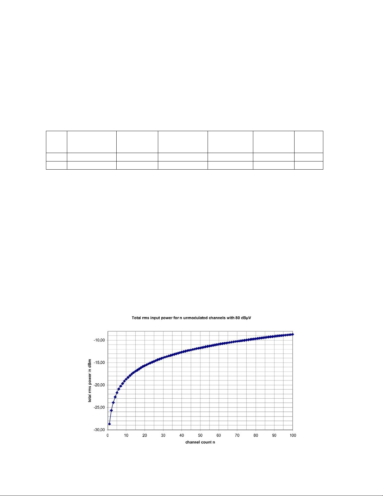
If the input level voltage of all channels is 80dBµV, the diagram below can be used to determine the total input power
level.
Figure 18 — Total RMS Input Power for N Unmodulated Channels with 80dBµV
OTOT-EM55X/XL Optical Transmitter Rev. x1 www.olsontech.com
22
Page 24
Example 1: The OTOT-EM55XL-PALD84 is specified for 84 TV channels. The nominal input level voltage per carrier
is 80dBµV, which corresponds to an input level power of -28.7dBm for one unmodulated channel only. For 84 un-
modulated channels the total input level will be –9.5dBm.
The specified, guaranteed AGC range of the OTOT-EM55X is +3 / -6dB. The recommended standard input level range
is therefore 77 to 86dBµV per channel or -12.5 to-3.5dBm total input power. In reality, however, the non-guaranteed
AGC range, will be significantly larger, typically about +5 / -8dB allowing total input level powers of about –14.5 to
–1.5dBm to be accepted without input power alarms.
Example 2: If the transmitter is only operated with 60 unmodulated channels, all with 80dBµV, the total input power
level can be determined to be –11dBm, therefore –1.5dB below the specified total RMS input power. This level is still
well within the AGC range of the transmitter. If the modulation of the carriers is switched on, however, the power of
each modulated carrier drops by about 4dB. In this case the total power also drops by 4dB to -15dBm.
This –15dBm is even below the extended AGC range and an input level alarm will be generated. In order to get back
into the AGC range, an increase of the input level to at least –9.5dBm (unmodulated carriers) is recommended, which
corresponds to 81.5dBµV in this example. It would even be beneficial to compensate also for the drop of the total in-
put power due to the AM modulation, which in most cases is about 4dB. In this case an input level of 85.5dBµV is re-
quested per carrier.
If the input power is lower or higher than required, the input LED lights yellow and a warning is generated. If the in-
put power is missing, the input LED lights red and an alarm is generated.
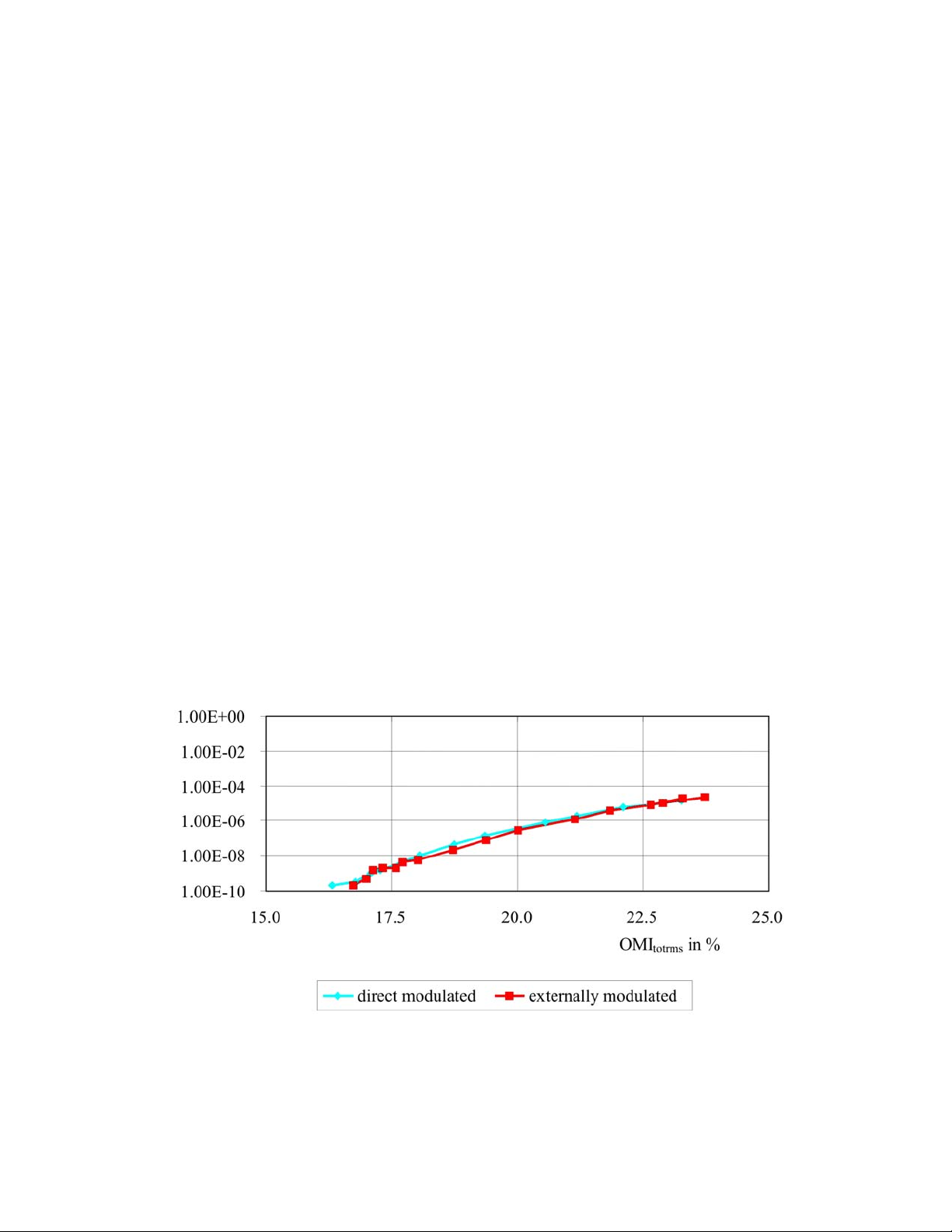
The AGC always tries to maintain the requested optical modulation index. The modulation index determines the
amount of bit errors, which come up due to overmodulation (clipping) of the transmitter.
The subsequent diagram shows the relationship between OMI
transmission. Obviously, OMI
should be below about 20% in order to obtain BERs better than 10-6.
totrms
and the bit error rate (BER) measured for QAM64
totrms
The BER also depends on the mix of AM, FM and QAM channels. If the QAM load is very small compared to the AM
and FM load the OMI
might be chosen about 1 dB higher while still obtaining the BER as given in the diagram
totrms
below.
Figure 19 — BER of Signals
The OTOT-EM55X is typically factory adjusted to achieve a BER of 10-9 with most frequency plans using the built in
AGC function. Experienced users are free to change the factory preadjusted OMI
by up to +3 / -3dB in steps of
totrms
0.2dB and/or to use the OTOT-EM55X in non-AGC mode. This gives the flexibility to optimize the total system CNR
or CSO/CTB performance.
OTOT-EM55X/XL Optical Transmitter Rev. x1 www.olsontech.com
23
Page 25

Mode: AGC-on, modulated carriers (user adjustable)
There is an alternative AGC mode available for measurement purposes only: AGC-on for modulated carriers. This
mode is only required when measuring CXMA (cross modulation distortions) in HFC networks and should not be used
in normal operations of HFC networks.
In CXMA measurements with AGC on the RF signal is increased by about 3dB due to the typical 100% duty cycle in
cross modulation measurements. This leads, however, to rather poor CXMA values measured. In order to compensate
for the increased gain, the AGC-on mode for modulated carriers has been implemented. Compared to the AGC-on
mode for unmodulated CW carriers, the gain is decreased by about 3dB for measurement purposes only.
Mode: AGC-off, (user adjustable)
In this mode, which is for experienced users only, the user has the flexibility to change the gain of the internal RF am-
plifier by +3 / -6dB according to his individual requirements. This adjustment, however, changes the RF input sensi-
tivity. The OMI
is measured for the applied input signal and selected gain and can be monitored on the LCD or via
totrms
the Ethernet interface. This mode should only be used with great care since the automatic protection against over-
modulation as given in the AGC-on mode is lost.
ITU frequency adjustments in DWDM applications (OTOT-EM55XL only)
The OTOT-EM55XL offers the feature to tune the optical frequency (respectively wavelength) of the transmitter by
±100 GHz in steps of 50GHz in order to enable DWDM applications. The tuning can be performed via the buttons on
the front panel or via the Ethernet interface.
Optical Power On /Off
The transmitter can be configured as a back-up transmitter with optical output power off. This allows turning on the
transmitter within less than 10 seconds in situations when a fast switching to a redundant transmitter is requested. The
optical power on/off switching can be performed via the buttons on the front panel or via the Ethernet interface.
SBS suppression setting (OTOT-EM55XXL only)
The OTOT-EM55XL enables theuser to change the SBS suppression of the transmitter. SBS (Stimulated Brillouin
Scattering) is a well known problem in long distance, high power transmission. For extremely coherent optical light,
SBS occurs already at optical powers of around +6dBm (4mW) in standard single mode fibers. With electronic meas-
ures the coherency of the light can be degraded which increases the SBS threshold that means the optical power which
leads to strongly perturbing SBS effects, destroying the CNR and CSO performance especially in the lower transmis-
sion frequency band.
If the SBS threshold is increased, another effect, the SPM (self phase modulation) arises. This effect degrades the CSO
performance in the higher frequency band. SPM depends on the total dispersion, which is present in the transmission
system.
SBS and SPM are both nonlinear effects in optical fibers and depend on
• the launched optical power
• the fiber properties (especially fiber loss and mode field diameter)
• the link properties (number of splices and total splice loss)
Both effects are worse with
• higher optical power
• lower mode field fiber diameter
• higher quality, lower loss fiber
• fewer, lower loss splices
Olson Technology tests the SBS and SPM performance of the OTOT-EM55XL with a standard IEC rec. G652 fiber
under worst case conditions: link containing no splices and providing a fiber loss of only 0.19dB/km. For this test ar-
OTOT-EM55X/XL Optical Transmitter Rev. x1 www.olsontech.com
24
Page 26

rangement the SBS suppression is specified keeping in mind the SPM problems.
SBS suppressions between 13 and 16.5dBm are recommended for fiber links with lengths of 65km or more. It is rec-
ommended to use the high SBS threshold settings (> 16.5dBm) for distances below 65km, and the lower SBS thresh-
olds for longer distances. The SBS threshold can be selected in 0.5dB steps between 13.0 and 19.0dBm for optimisa-
tion of the SBS performance in individual applications and link characteristics.
LED Display
The OTOT-EM55X/XL has a LED display (3 LED’s for MODUL, INPUT and OUTPUT) and a LCD in combination
with six menu buttons on the front panel for read and set parameters. For normal operation all LED’s should light
green. In case of warnings and alarms the responsible LED’s turn into yellow or red and the LCD shows further ex-
planations.
Module Status
Normal operation MODUL LED green
Non urgent alarms MODUL LED yellow
• fan 1 or fan 2 failure
• Power supply 1 or power supply 2 failure
• Laser cooler current >90 %. In this case the temperature of the trans-
mitter is too high. Improve thermal heat flow in order to decrease the
operating temperature.
• Laser bias current >130%. The laser has degraded.
In case of a fan or power supply failure the power supply/fan unit has to be replaced by
the customer. Olson Technology offers fans as regular spare parts.
Urgent alarms MODUL LED red
• Laser cooler current =100 %. In this case the temperature of the trans-
mitter is too high. Improve thermal heat flow in order to decrease the
operating temperature.
In case of an urgent alarm the transmitter is switched off internally and can only be restarted with a power on reset by disconnecting the power supply or via the NMS system.
INPUT Status
Normal operation INPUT LED green
Non urgent alarm INPUT LED yellow
Urgent alarm INPUT LED red
OUTPUT Status
Normal operation OUTPUT LED green
Non urgent alarm OUTPUT LED yellow
Urgent alarm OUTPUT LED red
• RF input low or high
• In AGC mode, AGC is out of range
• In Manual mode, OMI total RMS is out of range
• Laser bias current >130%. The laser has degraded.
• RF input is missing
• The output power drops below +5dBm: The transmitter is still working
but with reduced performance. It must be sent to Olson Technology for
maintenance.
• The output power drops below -4dBm: The transmitter is not working.
Send the unit to Olson Technology for maintenance.
OTOT-EM55X/XL Optical Transmitter Rev. x1 www.olsontech.com
25
Page 27

Push button / LCD interface
Security Items
When changing a parameter using the LCD interface in unlocked state, you have to enter a four digit numeric keycode
to login. The LCD login times out after 5 minutes with no key pressed. The factory default keycode is 1111. This keycode can be changed within the NMS server LCD menu or within the "server administration" web-page.
NOTE: Changing the keycode to 0000 disables the code and the parameters can be changed without entering a code.
Keys Default Usage
ESC key The ESC key is used mainly to cancel operations or to switch back a menu level.
ENTER key The ENTER key is used mainly to execute operations or to enter into a new menu level.
The ▼▲ Cursor keys are used to select a menu entry or to toggle between possible parameters.
The ◄► Cursor keys are used to select the letter to be changed in a number or a string or to scroll in text screens.
Menu Structure
Press ENTER at the Root-Screen to get a menu that contains the “NMS Server” menu entry first, followed by a list of
aliasnames of all detected RS485 bus devices. Please note that if the NMS Server does not run stand alone but em-
bedded in a device, then this device is treated like one (of many) RS485 bus devices.
Root-Screen
NMS Server (OTOT-EM55XXLa only) This menu contains all NMS Server specifics
Device No.1 (Device’s aliasname is shown) This menu contains all items that are specific to the device with the
shown aliasname
… (if further devices are communicating with the NMS server):
Device No. # (Device's aliasname is shown)
NMS Server menu(s) (OTOT-EM55XL only)
NMS Server
IP Settings Set the IP parameters of the server
Keycode Change the LCD keycode
Properties Show server properties like software- and hardware releases
Date & Time Adjust the server's real time clock
Reset Server Software reset the server
Rescan RS485 (Re)Search for RS485 devices on the bus
Logout Logout from LCD and return to Root-Screen
NMS Server->IP Settings NOTE: Dont forget to Save Settings after a change
Save Settings Save the changed IP parameters. The server gets reset after saving the new data
IP address Change or show the IP address
Netmask Change or show the netmask
Default router Set or show the default router
DHCP Set or show DHCP usage
OTOT-EM55X/XL Optical Transmitter Rev. x1 www.olsontech.com
26
Page 28

Optical Transmitter Device Menu(s)
Alarms / Warnings / Infos Show device's alarm, warning or info messages
Settings
AGC Mode Change or show the AGC mode
OMI, total RMS Change the OMI total RMS for AGC mode, related to the nominal OMI total RMS
RF Gain Change RF Gain for Manual mode, related to the nominal gain for nominal OMI total
RMS and nominal RF-Input power
SBS Suppression Change or show the SBS Suppression (OTOT-EM55XXLa only)
Channel Distance Change or show the Channel Distance for the CSO-control loop
ITU Frequency Change or show the lasers ITU wavelength (OTOT-EM55XXLa only)
Standby Change or show the Standby mode
Parameters
Output power Shows the optical Output power
RF Input power, totalRMS Shows the el. total RMS input power
If the el. input power is out of range for the selected OMI- or Gain-settings,
an input warning will be generated and the showed value is not valid.
RF Input power, nominal Shows the nominal el. total RMS input power for specified operation
RF Gain (AGC mode) Shows in AGC mode the actual Gain of preamplifier related to nominal.
If the el. input power is out of range for the required OMI setting, a in put
Warning will be generated and the showed value is not valid.
OMI total RMS (Man. mode) Shows for Manual mode the OMI total RMS related to nominal.
If the el. input power or the selected gain is out of range for a measurable OMI
value, an input warning will be generated and the showed value is not valid.
Laser Current Shows the Laser Current related to BOL
Cooler Current Shows the Cooler Current related to maximum
Module Temperature Shows the internal temperature
for actualiza tion of values just go back to the OVTX menu and enter again
Voltages Show the device’s internal voltages
Properties Show device properties like software- and hardware releases and dates
Miscellaneous Generating a reset or a reset to default settings
Aliasname Change device’s aliasname
Controlling the OTOT-EM55X/XL via a NEC
In general, the OTOT-EM55X/XL is connected to a NEC, which can be:
• a NEC which is directly embedded in the 19” housing. This is the case of an OTOT-EM55XL.
• a NEC-E-19’’, a network element controller in 19”-1RU housing providing 12 general purpose I/O ports or
• an embedded NEC in other Olson Technology products such as an optical amplifier or a direct modulated
transmitter DS26.
The network element controller (NEC) allows supervising and controlling the function of the transmitter and other
equipment, which is connected to the RS485 master interface, using the integrated Ethernet webserver (HTTP) inter-
OTOT-EM55X/XL Optical Transmitter Rev. x1 www.olsontech.com
27
Page 29
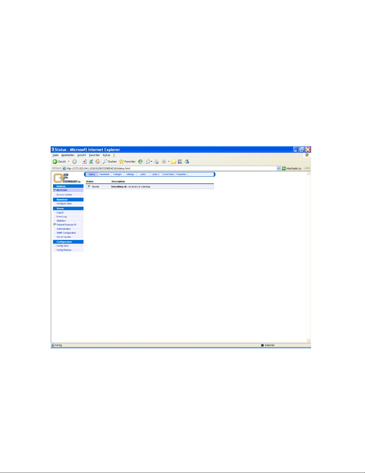
face.
In case of the OTOT-EM55XL the NEC-E is embedded and a connection between NEC-E and OTOT-EM55X has
been established internally. In order to enable the communication of an OTOT-EM55X/XL with a NEC, the RS485
slave port of the OTOT-EM55X/XL has to be connected with the RS485 master port of the NEC. The NEC Ethernet
interface has to be connected to a PC either directly via a crossed Ethernet cable or via a LAN. It is important to set the
IP address of the NEC in order to be compatible with the available LAN IP addresses. The IP address can be changed
using the pushbuttons and the LCD (please refer to NEC operating manual) In the example below the IP address has
been set to be 172.23.41.65.
Communicating with the NEC
If a Webbrowser gets in touch with the NEC of the transmitter a display as shown below will appear within the Web-
browser (e.g., MS Internet Explorer):
Figure 20 — Display of Webbrowser (Microsoft I.E.)
Selecting “Devices” all devices are shown which are connected to and recognized by the NEC. In the example above
only one device is connected to the NEC, the OTOT-EM55X, which is in the case an OTOT-EM55XL. This equipment
is currently displayed in the main window of the browser. At the same time Status is highlighted in the main window.
That means the main window currently displays the status of the OTOT-EM55XL.
By selecting a different menu in the main window Parameters, Voltages, Settings, Limits, Limits 2 and Properties of
the OTOT-EM55XL can be selected.
For location of a device connected to the NEC, the flag in front of the devices name can be used. Pressing this flag ini-
OTOT-EM55X/XL Optical Transmitter Rev. x1 www.olsontech.com
28
Page 30

tiates the module LED to blink for 10 seconds
Figure 21 — Log-in to the NEC (=Server)
In order to change values within the equipment recognized by the NEC, it is necessary to login to the NEC (=Server).
Otherwise, it will only be possible to view all the values, however, not to change them.
OTOT-EM55X/XL Optical Transmitter Rev. x1 www.olsontech.com
29
Page 31
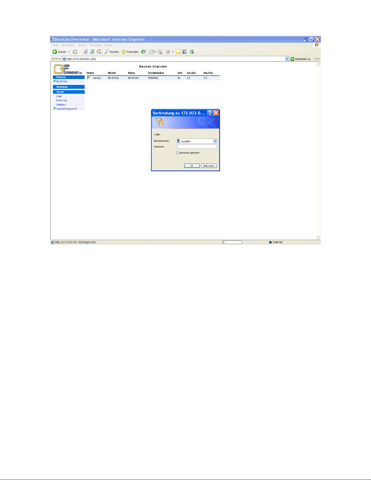
Figure 22 — Display of Login Menu
If login is selected, it is required to enter the user name and the appropriate password.
Note: The buttons occur in different languages depending on the actual Windows language setting.
After login, two additional menu buttons appear in the menu “Devices”: Devices update and Configure Slots. In the
main window, a button RescanAll allows to research the network for newly connected devices. Please note that new
devices should be automatically detected by the server when inserted into the RS485 bus, but if there are problems
then this button might help the server to find all devices.
OTOT-EM55X/XL Optical Transmitter Rev. x1 www.olsontech.com
30
Page 32
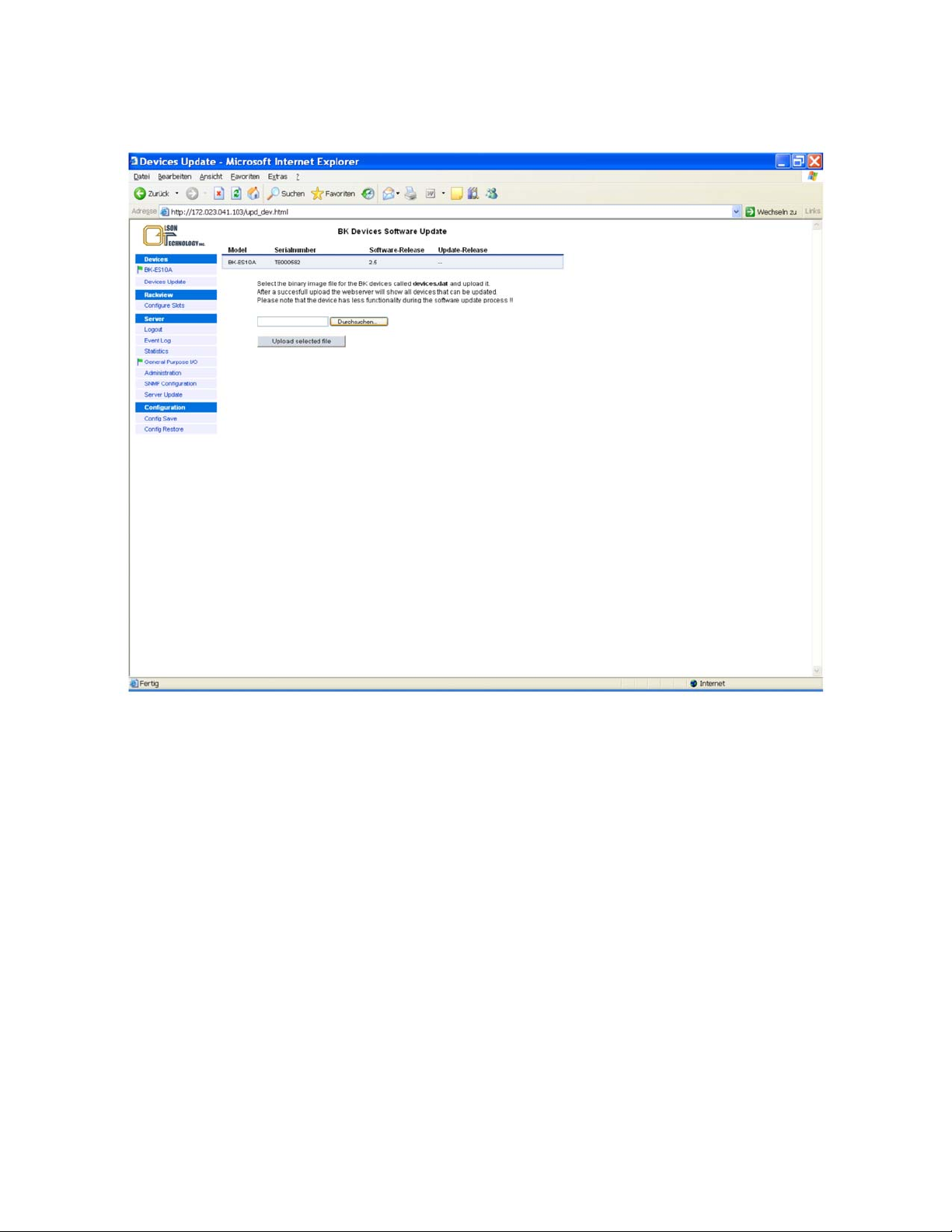
Devices Update
Using this menu button an update of the selected devices firmware is possible as can be seen in Figure 23.
Figure 23 — Devices Update Menu
OTOT-EM55X/XL Optical Transmitter Rev. x1 www.olsontech.com
31
Page 33
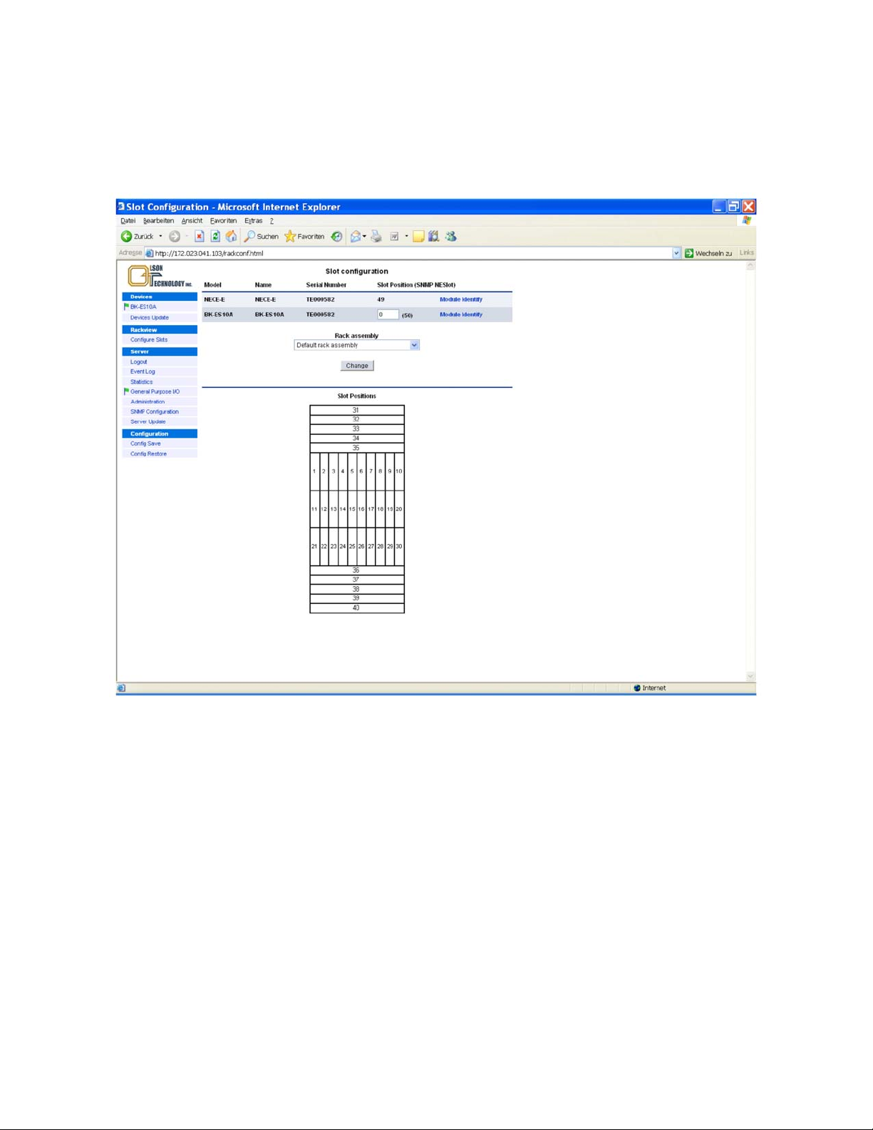
Configure Slots
The menu Configure Slots can optionally provide the possibility to assign a slot number to the specific device. The
number range is from 1 to 48. Number 49 is reserved. In case no numbers are assigned, number 50 and above are
automatically used. In case the device is an Olson Technology product mounted in a BBT00x subrack, the slot number
is detected and assigned automatically. For details, see the operational manual of the BBT00x.
Figure 24 — Configure Slots Menu
OTOT-EM55X/XL Optical Transmitter Rev. x1 www.olsontech.com
32
Page 34
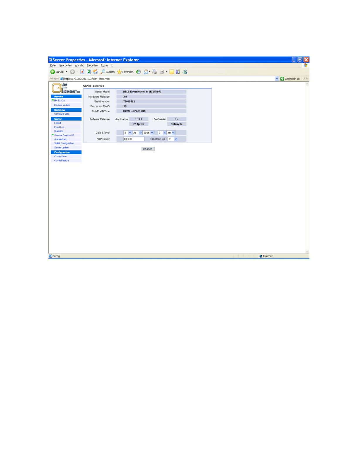
Server Properties
Selecting the menu Server the sever properties are displayed as shown in the following figure.
Figure 25 — Server Properties
OTOT-EM55X/XL Optical Transmitter Rev. x1 www.olsontech.com
33
Page 35
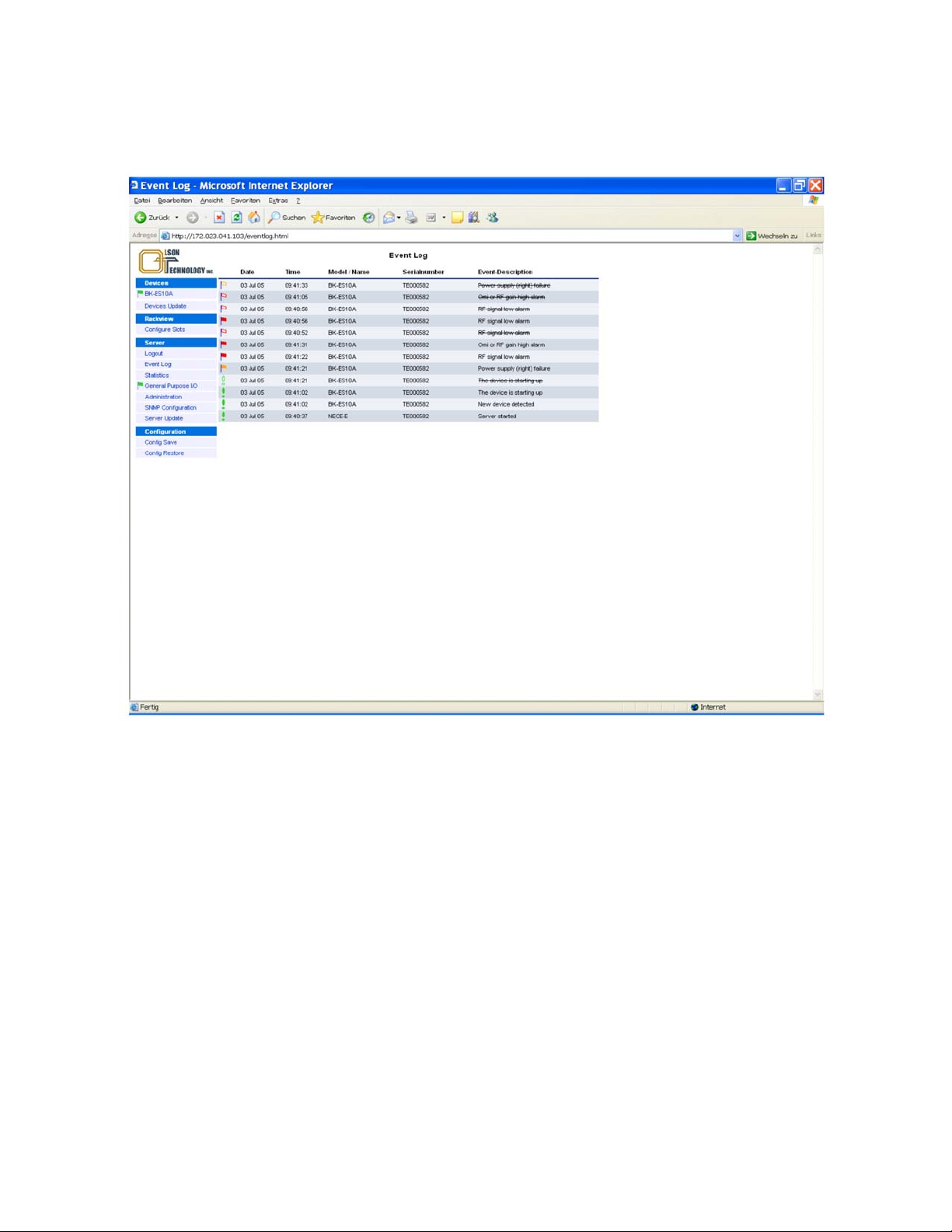
Event Log
After login the Event Log of the Server (=NEC) can be displayed. Depending on the operating conditions the event log
looks similar to what is shown in the picture below:
Figure 26 — Event Log Page
There are several marks, filled or unfilled, used to show all events.
• Green exclamation marks show events, which occur during normal operation. If the exclamation mark is filled
with green colour, which means that the event is still present. If the exclamation mark is empty (filled with
white colour) it means that the event has passed. At the same time, the previous shown event with filled exclamation mark is scratched out.
• Red flags show urgent alarms. The meaning of filled or unfilled flags is the same as with the exclamation mark.
• Orange flags show warnings. The meaning of filled or unfilled flags is the same as with the exclamation mark.
All events are shown with time stamps, the equipment causing the event, the serial number of the equipment and a de-
scription of the event. Since one NEC (=Server) might supervise many different equipment (transmitter, optical
switches, optical amplifiers, optical receivers …) the events of all the supervised equipment will be shown in the main
window. Up to 64 entries in the event log page are displayed. If this number is reached, the oldest entry is deleted in
order to provide space for a new entry.
OTOT-EM55X/XL Optical Transmitter Rev. x1 www.olsontech.com
34
Page 36
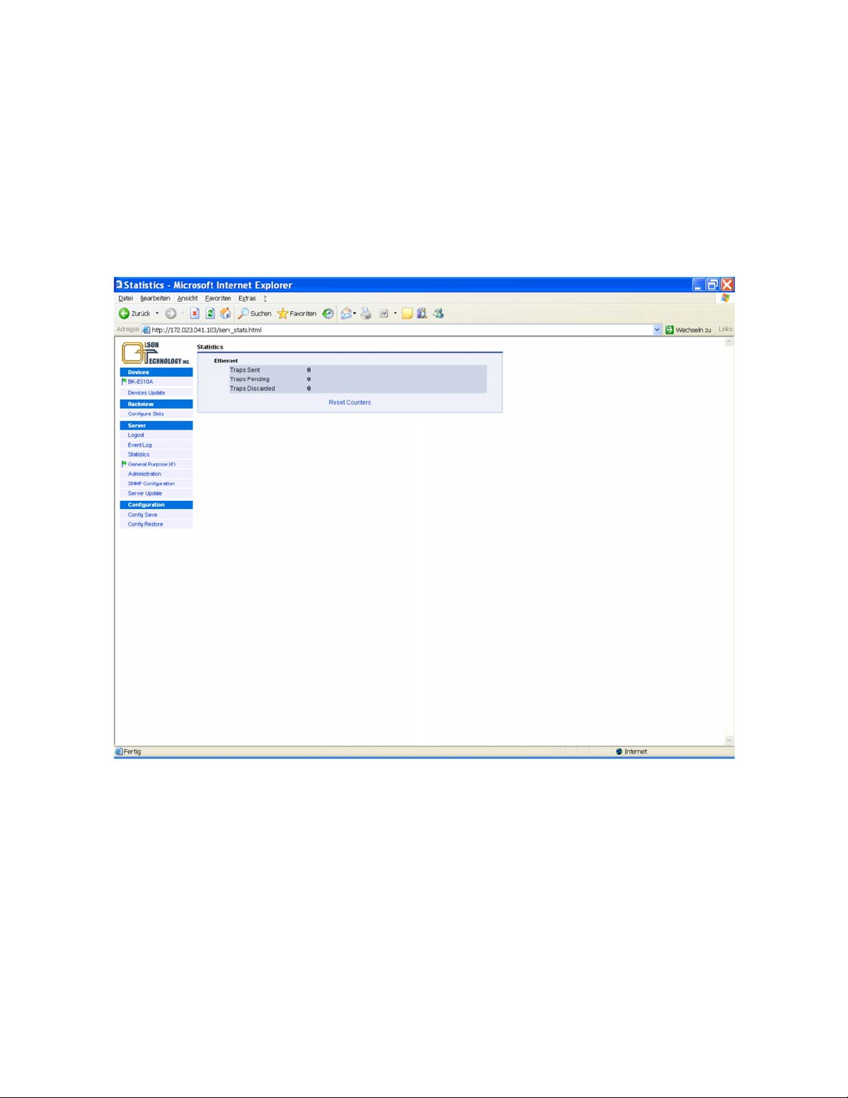
Trap Statistics
The statistics of sent, pending and discarded traps is shown in these fields and allows to check, whether the SNMP trap
settings are set correctly and/or the communication with the trap receiver works properly.
• Traps sent: The number of trap packets, which have been sent by the NEC.
Rem: Trap packets are counted, example: In case of 4 registered trap receivers the counter is increased by 4 for
each trap-event
• Traps pending: The number of trap packets, which the NEC-E has still to send.
• Traps discarded: The number of trap-packets the NEC-E has discarded. The counter is incremented in case of
any "discarded" trap, that means in any case of NEC-E trap memory-overflow or not in advance via SNMP Get
Request verified traps.
Figure 27 — Statistics Page
OTOT-EM55X/XL Optical Transmitter Rev. x1 www.olsontech.com
35
Page 37
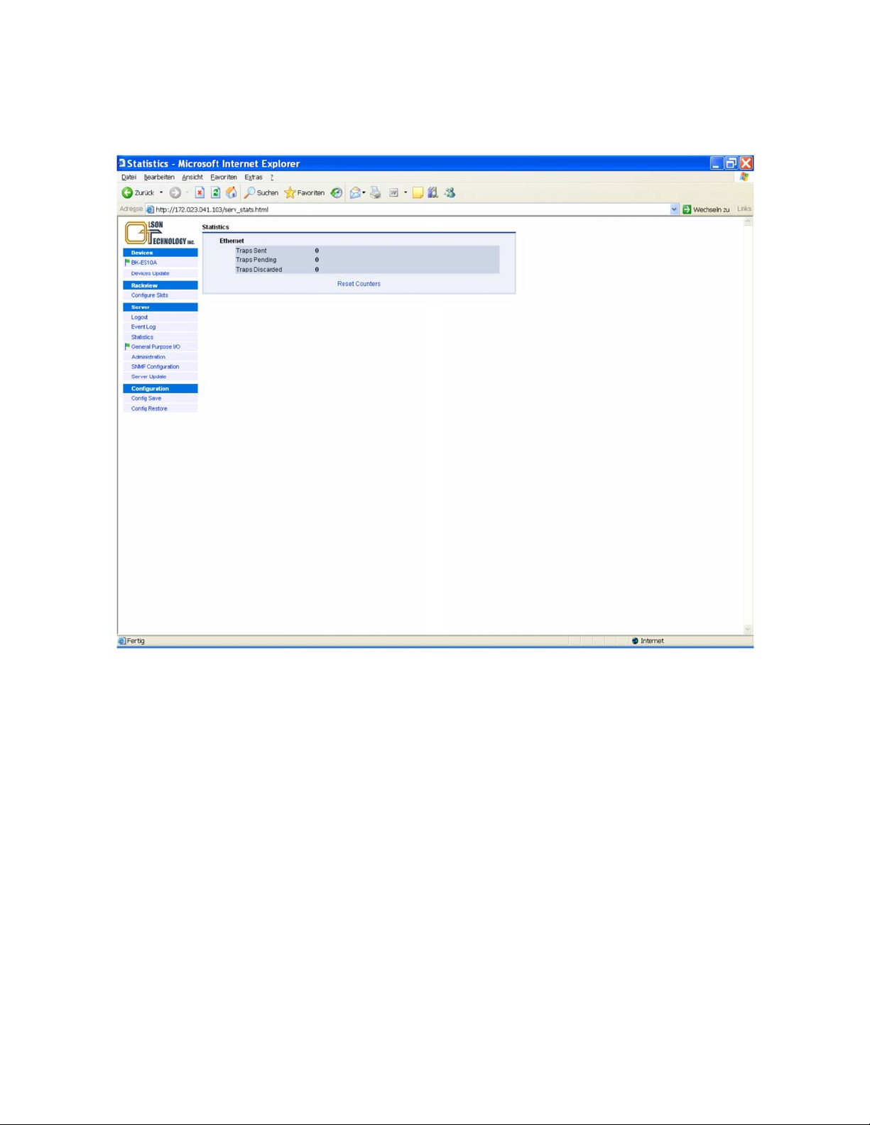
General Purpose I/O ports of Server = NEC (optional)
THE NEC-E provides optionally general purpose I/O ports for remote control functions. By selecting this item in the
Server Menu, a display as shown below will appear:
Figure 28 — I/O Ports Menu
In the I/O mode column, the mode of both the I/O port and all 4 input-only ports can be set. Figure 29 shows the
available options for the I/O port:
OTOT-EM55X/XL Optical Transmitter Rev. x1 www.olsontech.com
36
Page 38
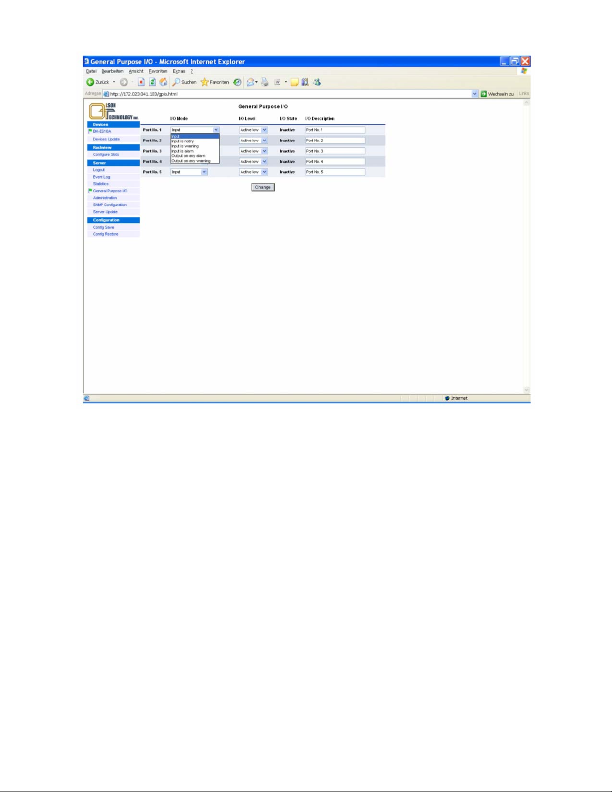
Figure 29 — Available Modes of Operation for the I/O Port
The options for the input ports are shown in Figure 30:
OTOT-EM55X/XL Optical Transmitter Rev. x1 www.olsontech.com
37
Page 39
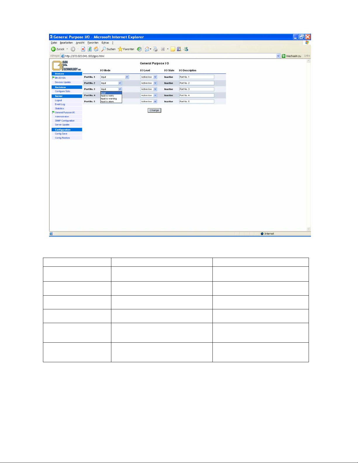
Figure 30 — Available Modes of Operation for the Input-only Ports
The available modes of operation for the I/O ports are given in the table below:
Port mode Description Application (examples)
Input
Input is notify
Input is warning
Input is alarm
Output on any alarm
Output on any warning
Input signal
(default = factory stetting)
Input signal creates a notify message (exclamation mark) in status display
Input signal creates a warning message (orange
flag) in status display
Input signal creates an alarm message (red
flag) in status display
Output will become active with any alarm.
Alarm limits for the OTOT-EM55XL can be set
in limit menus of OTOT-EM55XL
Output will become active with any warning.
Warning limits can be set in limit menus of
OTOT-EM55XL
Somebody entered the headend
(available on ports 1 … 5)
Somebody entered the headend
(available on ports 1 … 5)
Temperature in room is too high
(available on ports 1… 5)
Headend failure
(available on ports 1-5)
(available for port 1)
(available for port 1)
All ports can be set to be either active low or active high. A description of the I/O port function can be added to each
port optionally
Examples of I/O port status information
An OTOT-EM55XL polls also an EDFA via the RS-485 interface.
Please note, that the I/O port #0 is directly related to the transmitter unit whereas all other I/O ports (#1-5) are related
to the NEC.
OTOT-EM55X/XL Optical Transmitter Rev. x1 www.olsontech.com
38
Page 40

• Let´s guess, that I/O #0 is set to output on any warning (and alarm)
• Let´s guess, that I/O #1 is set to output on any alarm (no warnings)
Now let’s assume some alarm situations:
1. RF input of OTOT-EM55X is low (warning); Optical Amplifier has no warnings or alarms
The I /Os will be:
Output #0: active
Output #1: inactive
2. RF input level of OTOT-EM55XL is extremely low (alarm)
The I/Os will be:
Output #0: active
Output #1: active
3. Optical input power level of Optical Amplifier is low (warning); OTOT-EM55X has no warnings or alarms:
The I/Os will be:
Output #0: inactive
Output #1: inactive
4. Optical input power level of Optical Amplifier is low (warning); OTOT-EM55X has no warnings or alarms:
The I /Os will be:
Output #0: inactive
Output #1: inactive
5. Optical input power level of Optical Amplifier is low (warning); OTOT-EM55X has no warnings or alarms; I/O #2
is set to alarm on input;I/O #2 receives an alarm
The I /Os will be:
Output #0: inactive
Output #1: active
6. Optical input power level of Optical Amplifier is very low (alarm); OTOT-EM55X has no warnings or alarms:
The I /Os will be:
Output #0: inactive
Output #1: active
OTOT-EM55X/XL Optical Transmitter Rev. x1 www.olsontech.com
39
Page 41
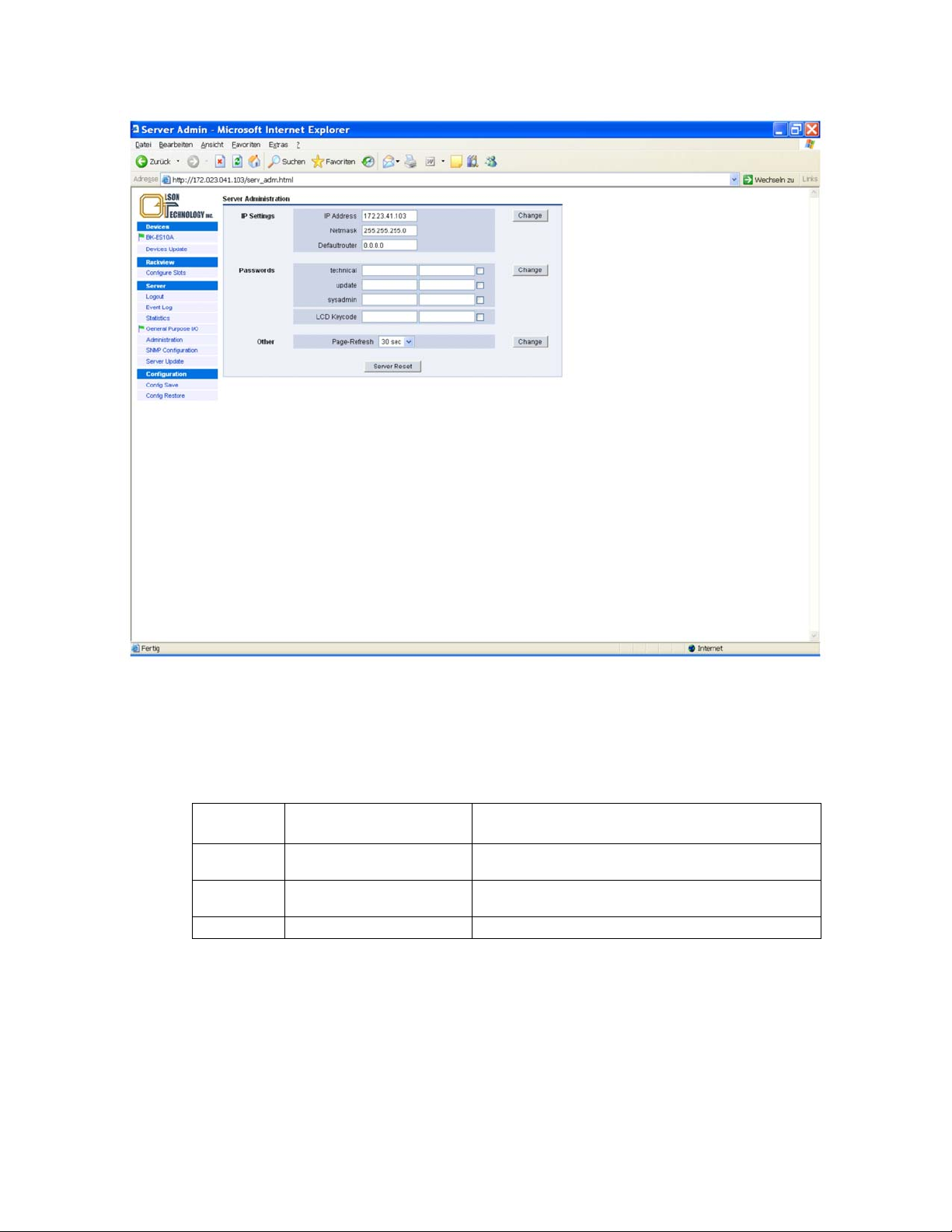
Server Administration
Figure 31 — Server Administration Menu
The server administration menu allows modifying the IP parameters, the user names and passwords and the interval,
how fast the WebBrowser pages are updated. The update interval has to be chosen carefully, especially if the number
of devices polled by the NEC is quite high, in order to avoid too much communication traffic. The new parameters in
the different blocks are executed by clicking on the change button of the individual block. There are three levels of
login priorities defined.
Username
technical technical
update update
sysadmin sysadmin
Factory Default Pass-
word
Description
In this level all parameters can be changed, except the update
and server administration items.
In this level (additionally to the "technical" level) the server and
device update processes can be executed.
System administrator level, all tasks can be done.
OTOT-EM55X/XL Optical Transmitter Rev. x1 www.olsontech.com
40
Page 42
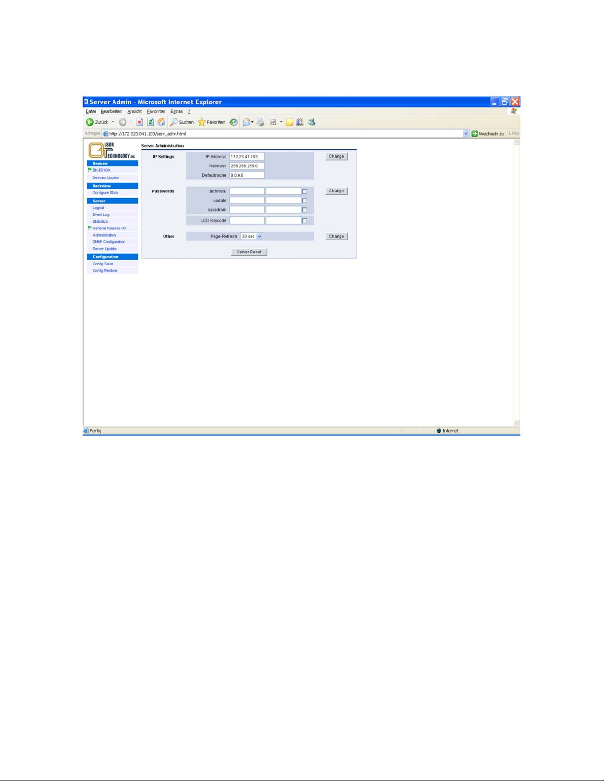
SNMP Configuration
A SNMP configuration menu is available as shown in the picture below:
Figure 32 — SNMP Configuration Menu
Traps
The SNMP configuration menu allows entering the IP trap receiver addresses for up to 4 trap receivers, and to change
the trap community strings for trap receiver #1 and trap receivers #2 to #4. Additionally all traps can be dis-
abled/enabled. Furthermore, the inventory traps might be disabled or enabled. A further button allows selecting the
SCTE HMS alarm generation:
• Disable all traps
• Enable all traps
Enable and resend all traps; this function is helpful for testing SNMP communication with the trap receiver(s)
Communities
Separate strings can be allocated to the get community and the set/get community.
OTOT-EM55X/XL Optical Transmitter Rev. x1 www.olsontech.com
41
Page 43

Special Settings
®
CABLEwatch
NMS
Used Not Used
SNMP Get/Set Community Names cannot be modified. (Web
and SNMP)
Web Rackview and Rackview Configuration Pages Handling
are directly linked with CABLEwatch
Rem.: A slot number must be assigned to all moduls without automatic slot detection (e.g. all 19 inch components. This has
to carried out by Rackview Configuration. The slot number acts as a reference number for all SNMP accesses.
Of all modules without slot assignment only one will be displayed in SNMP with slotnumber 50. All others are not
shown until they get a slotnumber assigned.
(**) available from NEC-E Software Release 1.11
Variables in the RFC1213 system group are write-protected.
it is possible to write sysLocation and sysContact indirectly
via the variables neLocationCity und NeLocationStreet of the
OLSON TECHNOLOGY-HFC862-HMSNE-MIB
(ahmsne.mib).
®
NMS
SNMP Get/Set Community Names can be modified. (Web
und SNMP)
Web Rackview and Rackview Configuration Pages are independent from CABLEwatch® NMS
All modules without slot assignment are dispayed in SNMP
with the slot numbers 51, 52, ...
(**)Variables in the RFC1213 system group are writeable.
(however with restricted length, not 256 Byte !!)
HMS Traps Compliance
( see also SCTE-HMS-ALARMS-MIB und SCTE-HMS-COMMON-MIB )
Minor Compliant
hmsAlarmEvent Trap is sent with ENTERPRISE OID alarmsIdent (1.3.6.1.4.1.5591.1.2), instead of OID scteHmsTree
(1.3.6.1.4.1.5591.1) as demanded by HMS MIB
hmsColdStart Trap is sent to RFC1215 with ENTERPRISE
OID commonIdent (1.3.6.1.4.1.5591.1.3), instead of OID
scteHmsTree (1.3.6.1.4.1.5591.1) as demanded by HMS MIB
and with Trap-Type COLD START.
(1)
As demanded by HMS MIB, hmsAlarmEvent Trap is sent
with ENTERPRISE OID scteHmsTree (1.3.6.1.4.1.5591.1).
As demanded by HMS MIB, the hmsColdStart Trap is sent
with the ENTERPRISE OID scteHmsTree
(1.3.6.1.4.1.5591.1) and with Trap-Type ENTERPRISE
SPECIFIC + Specific-Trap-Type 0.
Full Compliant
HMS Notifications
Enabled
All messages of type "Notification" are sent as Trap and are
inserted in the SNMP SCTE HMS tables. Since HMS does
not recognize Notifications, “HMS-Severity” minor is reported
(1)
All messages of type "Notification" are not sent as Trap and
are not inserted in the SNMP SCTE HMS tables.
In the Webbrowser the Notifications are still shown
Disabled
hfcInventory Format
T-Nova, E531i
The SNMP variable "hfcInventoryFabricData" of the
T-NOVA-HFC-INVENTORY-MIB is provided in the format
defined by Biedenbach (T-Nova, E531i)
(1)
The SNMP variable "hfcInventoryFabricData" of the
T-NOVA-HFC-INVENTORY-MIB is provided in the format
defined by Herberg (DKS, T12-9)
DKS, T12-9
(1) Default setting up to NECE Software Release 1.10
Trap Verify
If traps are to be transmitted via non permanent links like dial-up links (e.g. using ISDN or standard analog modem), it
is important to verify that the link to the trap receiver is working before any SNMP traps are sent. Otherwise, the traps
could get lost.
With NEC-E software 1.10.x and later, several settings have been introduced to obtain a verification of the link be-
tween the trap transmitter (=NEC) and trap receiver:
• Verify before trap. If enabled, via SNMP Get Request the “sysDescr” OID of the host having the “Trap Verify
Receiver” IP address (see below) is executed before the pending traps are sent. Only after successful reply all
OTOT-EM55X/XL Optical Transmitter Rev. x1 www.olsontech.com
42
Page 44

pending traps are sent. For permanent-on links (e.g. LANs), “disabled” is the recommended setting. For other
links “enabled” is the recommended setting.
• Trap verify receiver: Here the IP address of the receiver, verifying the link, can be entered. In many cases, it
might be one of the trap receiver addresses as entered in 0. However, in dial-up links, optionally the IP address
of a receiving modem (e.g. ISDN router) could be used instead of the IP address of a real trap receiver.
• Timeout: A timeout time between 30 and 600 seconds might be specified, in order to detect a link error. The
NEC-E is waiting the specified time for replies on the “sysDescr” SNMP Get Requests. After this time all
pending traps are sent, regardless of a reply has arrived or not. Important:
In this case of timeout the “traps sent”
and the “traps discarded” counter (see below) are incremented.
• Trap Accumulation Time: It is possible to collect traps during the “Tr ap accumu la t ion t ime ”, which can be set
between 0 and 60 seconds, until they are transmitted all together. This feature helps to reduce connection fees in
dial up connections. In the following cases the accumulated traps are in any case released for sending:
• The internal trap memory is 3/4 filled.
• The SNMP agent of the NEC-E is polled by any kind of manager.
• Test “trap verify receiver” response: This function is very useful to set up and test the communication in modem
links. By clicking this link it can be tested, whether the “Trap Verify Receiver” is answering correctly on the
SNMP Get Request. (Timeout after 30 seconds). This link is only visible, when “Verify before Trap” is enabled.
OTOT-EM55X/XL Optical Transmitter Rev. x1 www.olsontech.com
43
Page 45
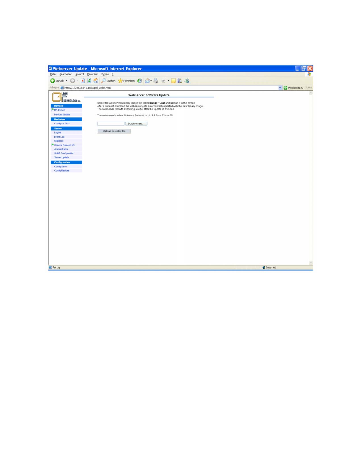
Server Update
It is possible to update the Server (=NEC) firmware by uploading it to the optical transmitter using the Webserver
software upload menu as shown below.
Figure 33 — Server Update Menu
A Server software update might be required, if new equipment has to be supervised by the NEC, connected to the
RS485 (master) interface, or if the changes to the WebBrowser- or SNMP- Ethernet interfaces have to be imple-
mented.
Note: The buttons occur in different languages depending on the actual Windows language setting.
OTOT-EM55X/XL Optical Transmitter Rev. x1 www.olsontech.com
44
Page 46
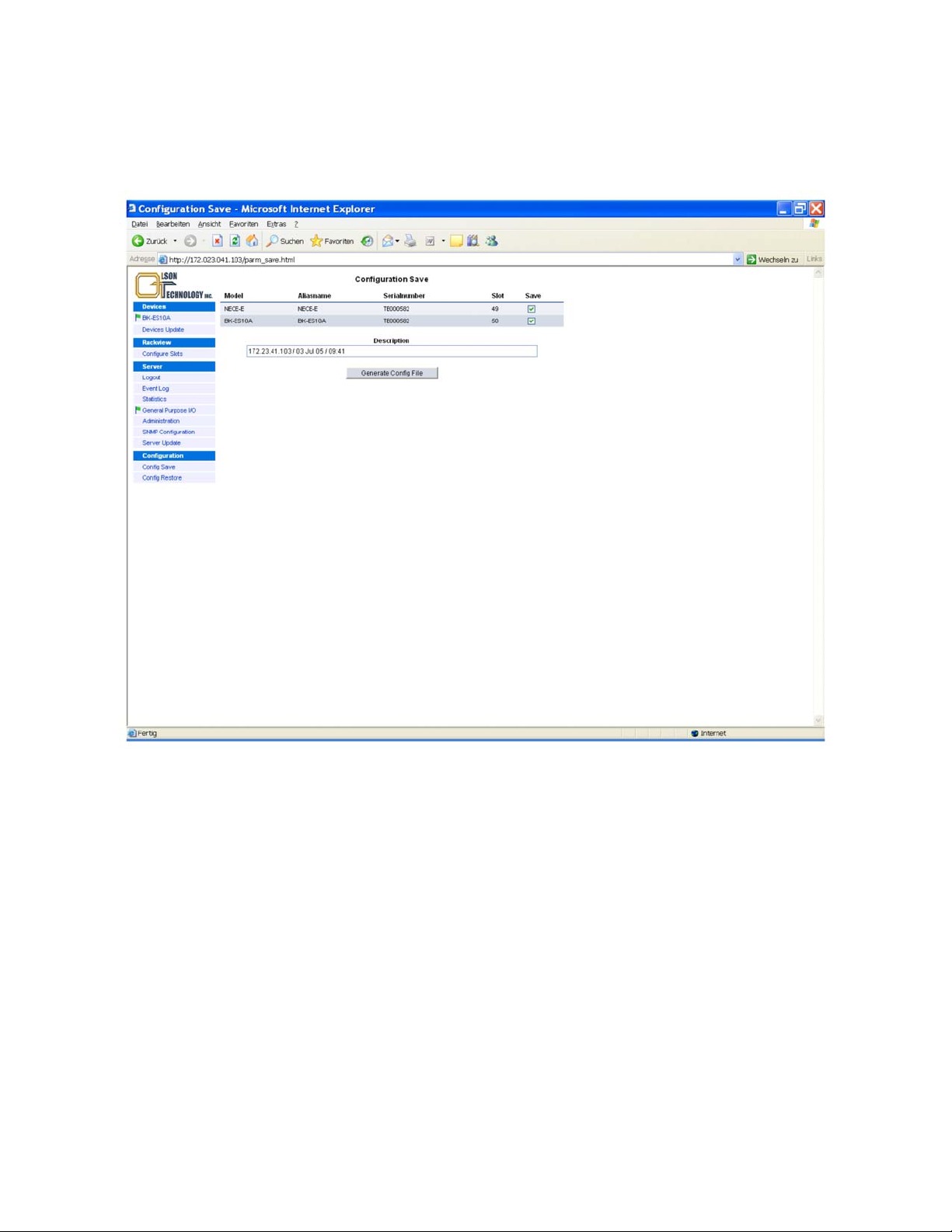
Config Save
From NEC appl. SW release 1.11.x a configuration menu is optionally available. The menu allows the user to save
and/or to restore the configuration settings of the equipment controlled by the NEC. Pushing the “Config Save” button
the following picture appears:
Figure 34 — Config Save Menu
A table of the controlled devices with model name, alias name, serial number and slot number is displayed. Devices
can be marked for configuration saving using last column of the table. Pressing the “Generate Config file” button a file
with the settings of the selected devices is generated and stored in the flash memory of the NEC. To save the file lo-
cally, the button “Save generated Config file” can be used. The default file name is displayed below the button. Also
this link can be used to initiate the file storage.
OTOT-EM55X/XL Optical Transmitter Rev. x1 www.olsontech.com
45
Page 47
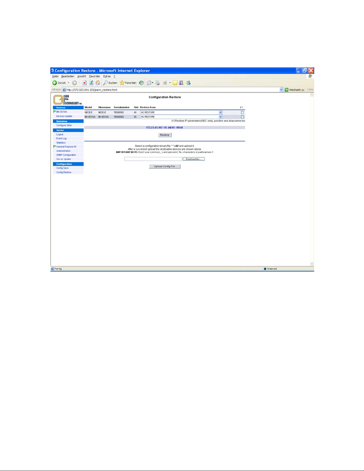
Config Restore
Pushing the “Config Restore” button the file saved in the NEC memory is available for restoring as shown in the pic-
ture below.
Figure 35 — Config Restore Menu
In the column “Restore from” the available configurations can be selected by model name, alias name, serial number
and slot number. The “Restore” button starts the restoration.
In the last column it can be selected if the equipment should also take over the aliasname and slotnumber. In this way
the device can be completely recovered in its settings. In this manner it is easy to configure a replacement unit or re-
store the configuration of an entire group of devices e.g. after a system crash.
OTOT-EM55X/XL Optical Transmitter Rev. x1 www.olsontech.com
46
Page 48
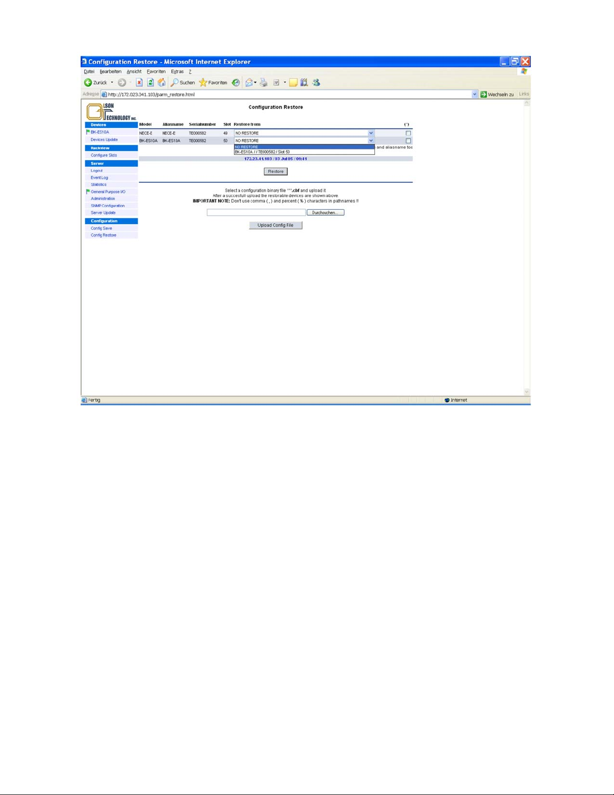
Figure 36 — Config Restore Menu
In case configuration settings of a device should be transferred to another device e.g. in a different system, the mark
has to be deselected. Only the configuration settings are then applied, the aliasname and slotnumber of the device is
not altered. Using the “Upload Config file” button a local file can be loaded into the NEC memory and further on be
used for restoring configuration settings as described.
OTOT-EM55X/XL Optical Transmitter Rev. x1 www.olsontech.com
47
Page 49
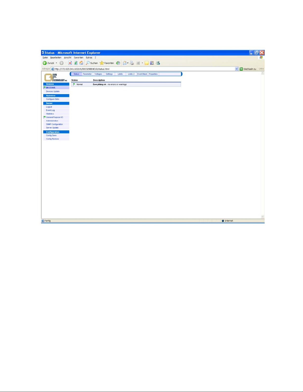
Status Menu
The figure below shows the status menus of the OTOT-EM55X.
Figure 37 — Status Menu of OTOT-EM55X
The actual status of the transmitter is shown using a mark and a description. There are several marks, filled or unfilled,
used to show all events.
• A green flag indicates that the transmitter is working properly.
• An orange flag shows a warning. A certain parameter is out of the nominal range. The reason for that should be
checked and solved as soon as possible.
• A red flags show an urgent alarms. An immediate action is required to fix the failure.
• An exclamation mark provides a message about a certain mode of operation or change
OTOT-EM55X/XL Optical Transmitter Rev. x1 www.olsontech.com
48
Page 50
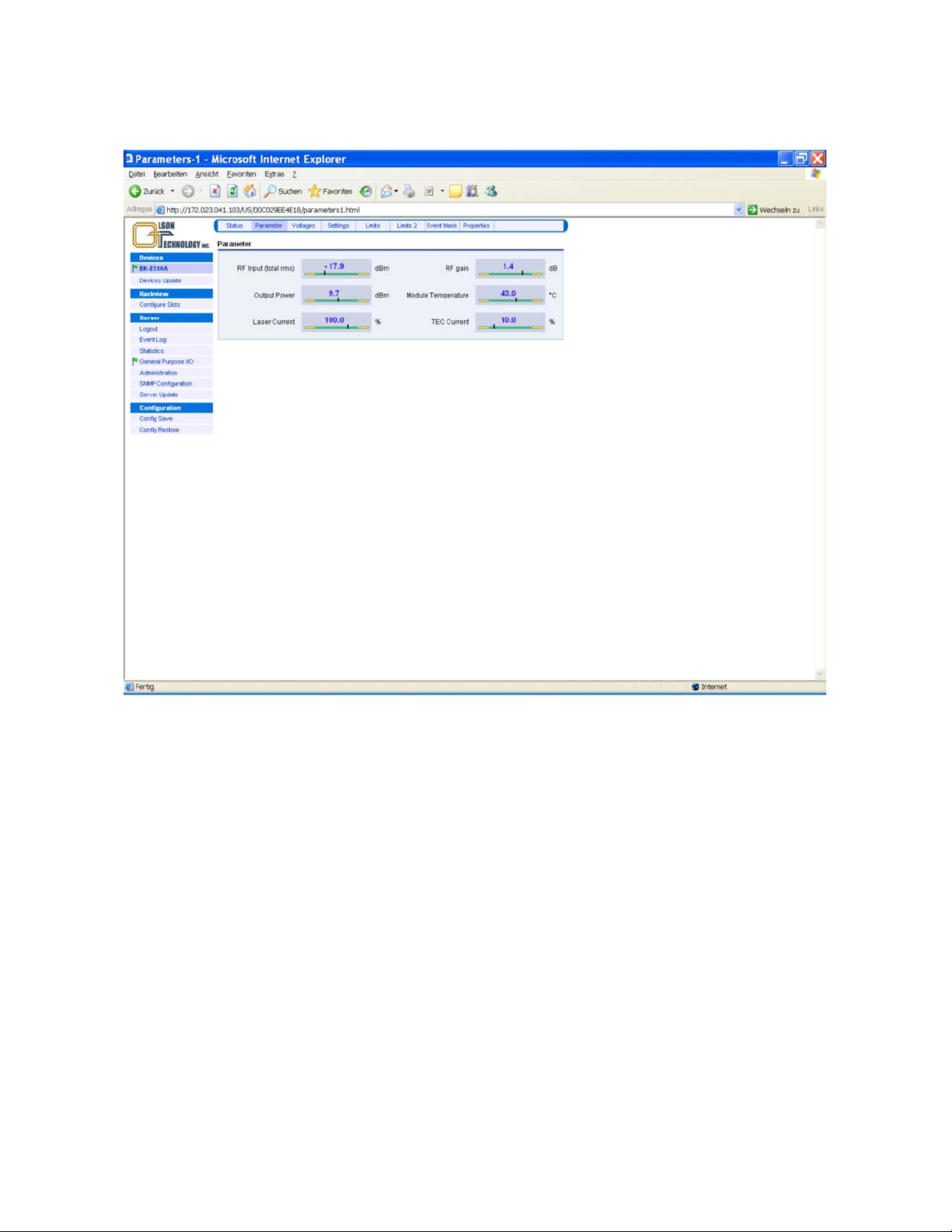
Parameters Menu
The parameters menu displays the most important values of the transmitter for operation.
Figure 38 — Parameters Menu of OTOT-EM55X
For proper operation, the black vertical bars should meet the green fields. Note: The scaling of the green and yellow
fields might be different in order to obtain a good reading, especially of the green field.
OTOT-EM55X/XL Optical Transmitter Rev. x1 www.olsontech.com
49
Page 51
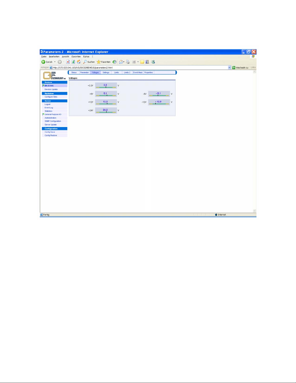
Internal Voltages
The voltages menu displays all internal supply voltages like shown below.
Figure 39 — Internal Voltages Menu of OTOT-EM55X
For proper operation, the black vertical bars should meet the green fields. Note the thresholds for alarms are not ad-
justable by the user but are factory settings only.
OTOT-EM55X/XL Optical Transmitter Rev. x1 www.olsontech.com
50
Page 52
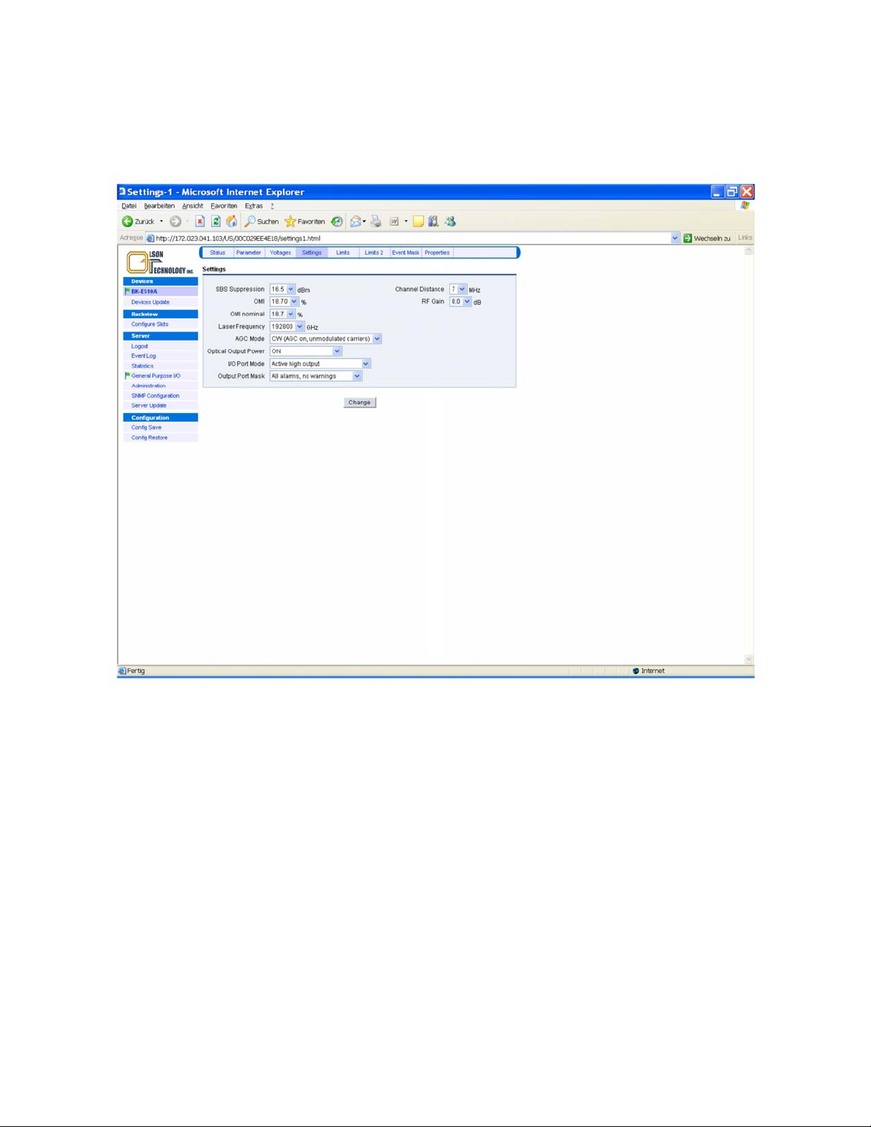
Settings Menu
This menu allows changing some basic adjustments of the OTOT-EM55X. Note: Some of the settings require certain
hardware and software releases. Please refer to the manual supplied with the transmitter if some options are different
or missing compared to this picture.
Figure 40 — Settings Menu of OTOT-EM55X
OTOT-EM55X/XL Optical Transmitter Rev. x1 www.olsontech.com
51
Page 53
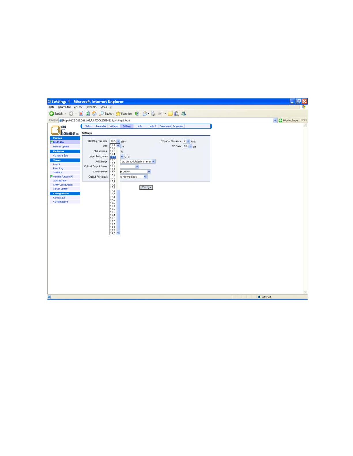
Changing the SBS Threshold
The picture below shows, how to change the SBS suppression (threshold) between 13.0 and 19.0dBm for the
OTOT-EM55XL (be aware that the OTOT-EM55X has a fixed SBS threshold of 16dBm). It is important to understand,
that the SBS setting has a major impact on the transmission performance, especially for very long fiber transmission
(e.g. 100km) and high frequencies (860MHz). The SBS suppression can be adjusted in 0.5dB steps (calibrated). From
NEC application software release 1.11 the adjustment can be carried out in 0.1dB-steps, which are in this case inter-
polated, the 0.5dB steps are still calibrated.
Figure 41 — Changing the SBS Threshold of the OTOT-EM55XL
OTOT-EM55X/XL Optical Transmitter Rev. x1 www.olsontech.com
52
Page 54
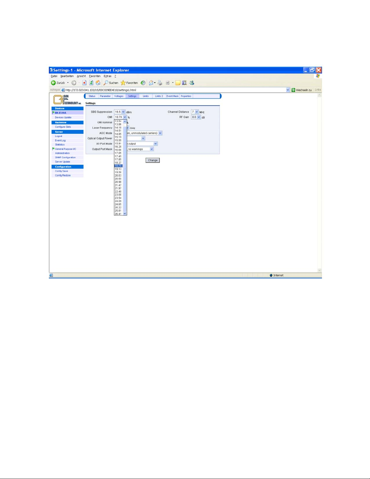
Changing the OMI
(AGC on modes only)
totrms
The picture below shows, how to adjust the OMI total RMS, in order to optimize the transmission performance in
terms of CNR, CSO, CTB and BER.
Figure 42 — Setting the OMI Total RMS on the OTOT-EM55X
With software release 2.0, the OMI
OMI
was shown relative (in dB) to a nominal value. The display in % enables an easy comparison with the graphs
totrms
totrms
(OMI
in the figure beyond) is shown in %. In previous software releases,
rms
as shown in Figure 18. For that reason, OTOT-EM55X application software release 1.12 and later supports this fea-
ture.
Notes:
• OMI nominal refers to a factory setting and cannot be changed by the user.
• OMI
• The setting range for OMI
setting is only relevant in AGC-on mode.
totrms
might change slightly from device to device due to production tolerances.
totrms
OTOT-EM55X/XL Optical Transmitter Rev. x1 www.olsontech.com
53
Page 55
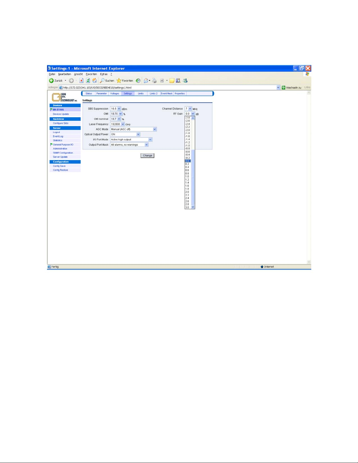
Setting the RF Gain (AGC off mode only)
The picture below shows how to adjust the RF gain, in order to optimize the transmission performance in terms of
CNR, CSO, CTB and BER.
Figure 43 — Setting the RF Gain on the OTOT-EM55X
OTOT-EM55X application software release 2.0 and later supports this feature.
Notes:
• The RF gain setting is only relevant in AGC-on mode.
• The setting range for RF gain might change slightly from device to device due to production tolerances.
• Changing the RF gain changes the input sensitivity of the OTOT-EM55X in AGC off mode; 0dB is the nominal
RF gain. Setting the RF gain to e.g. 2dB improves the input sensitivity of the OTOT-EM55X from 80dBµV to
78dBµV.
OTOT-EM55X/XL Optical Transmitter Rev. x1 www.olsontech.com
54
Page 56
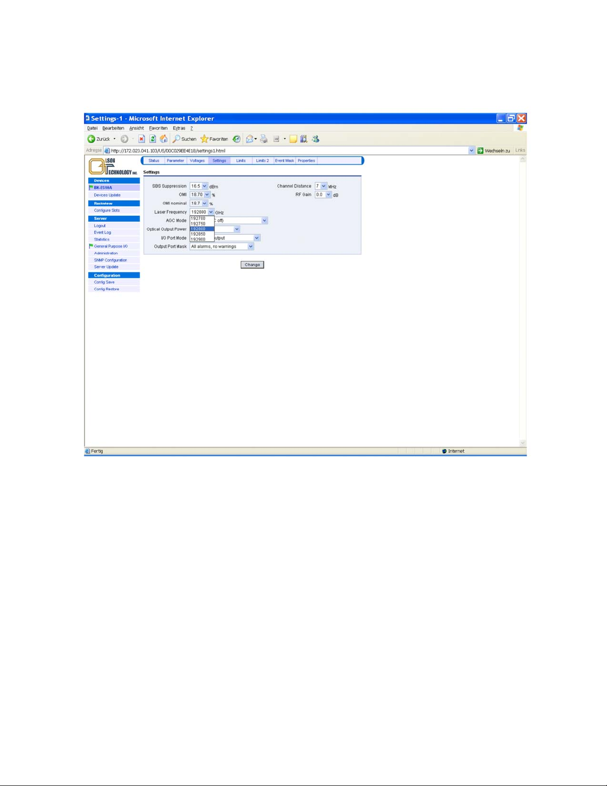
Changing the ITU frequency of the OTOT-EM55XL
The figure below shows, how to change the ITU frequency (optical wavelength) of the transmitter in steps of 50GHz
up to ±100GHz (not available for OTOT-EM55X).
Figure 44 — Changing the ITU Frequency of the OTOT-EM55XL
OTOT-EM55X/XL Optical Transmitter Rev. x1 www.olsontech.com
55
Page 57
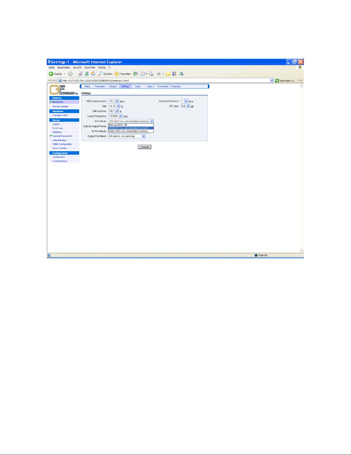
Changing the AGC Mode
The transmitter can be operated in non-AGC (manual) as well as two different AGC modes.
Figure 45 — Selecting the AGC Mode of the OTOT-EM55X
OTOT-EM55X/XL Optical Transmitter Rev. x1 www.olsontech.com
56
Page 58
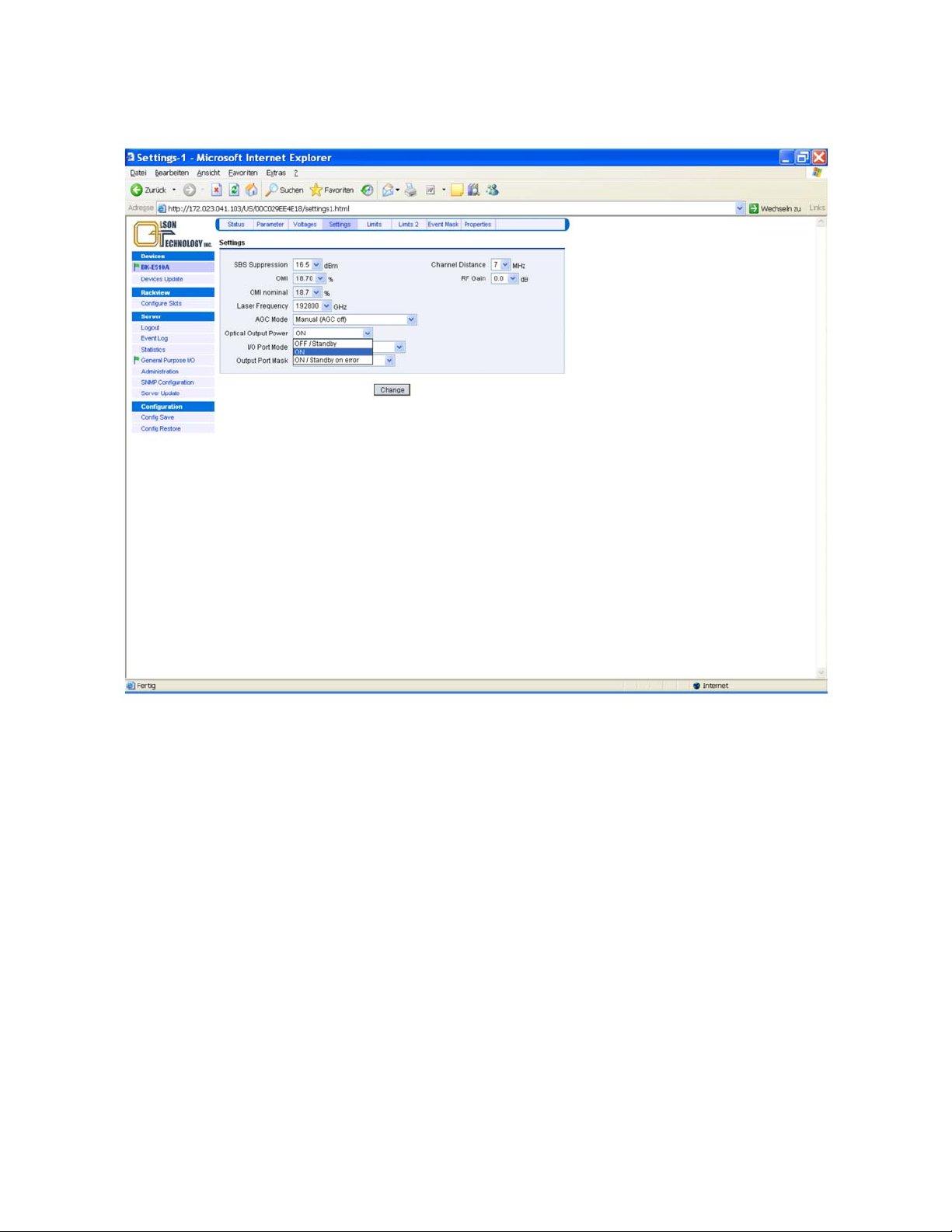
Changing the Optical Output Power Mode
There are three different output power modes available for the OTOT-EM55X as shown in the picture below:
Figure 46 — Changing the Optical Output Power Mode of the OTOT-EM55X
• OFF / Standby. By selecting this mode the OTOT-EM55X will operate with optical output power switched off.
However, the laser temperature is still kept at the operating temperature by driving the Peltier cooler enabling a
fast switching-on time. Additionally the RF input monitor is operating. Note: In future software releases it is intended not to completely switch off the optical power but to decrease the optical power below a certain threshold (e.g. –3dBm) in order to enable the supervision of the laser in standby mode and in order to enable the supervision of the fiber link between the OTOT-EM55X and the subsequent EDFA or RX.
• ON. The transmitter output power is always on (default = factory setting).
• ON / Standby on alarm. The transmitter output power is on, as long as there is no internal alarm. In case that an
alarm condition occurs, the output power is switched into standby mode. This operating mode has been designed
especially for redundant transmitter operation: If e.g. an RF input alarm occurs, the optical output power is
switched to standby mode. This consequently should also disable the subsequent EDFA. If a pair of two
OTOT-EM55X with subsequent EDFA are intended to be used for redundant operation (master/slave mode this
feature will automatically switch from the master TX + EDFA to the slave TX + EDFA. In this case the I/O No.
0 ports of both OTOT-EM55X have to be connected and the master/slave settings have to be chosen. Note: The
requirements for an alarm condition can be set by adjusting the alarms thresholds.
This feature request software release 2.0 or later.
OTOT-EM55X/XL Optical Transmitter Rev. x1 www.olsontech.com
57
Page 59
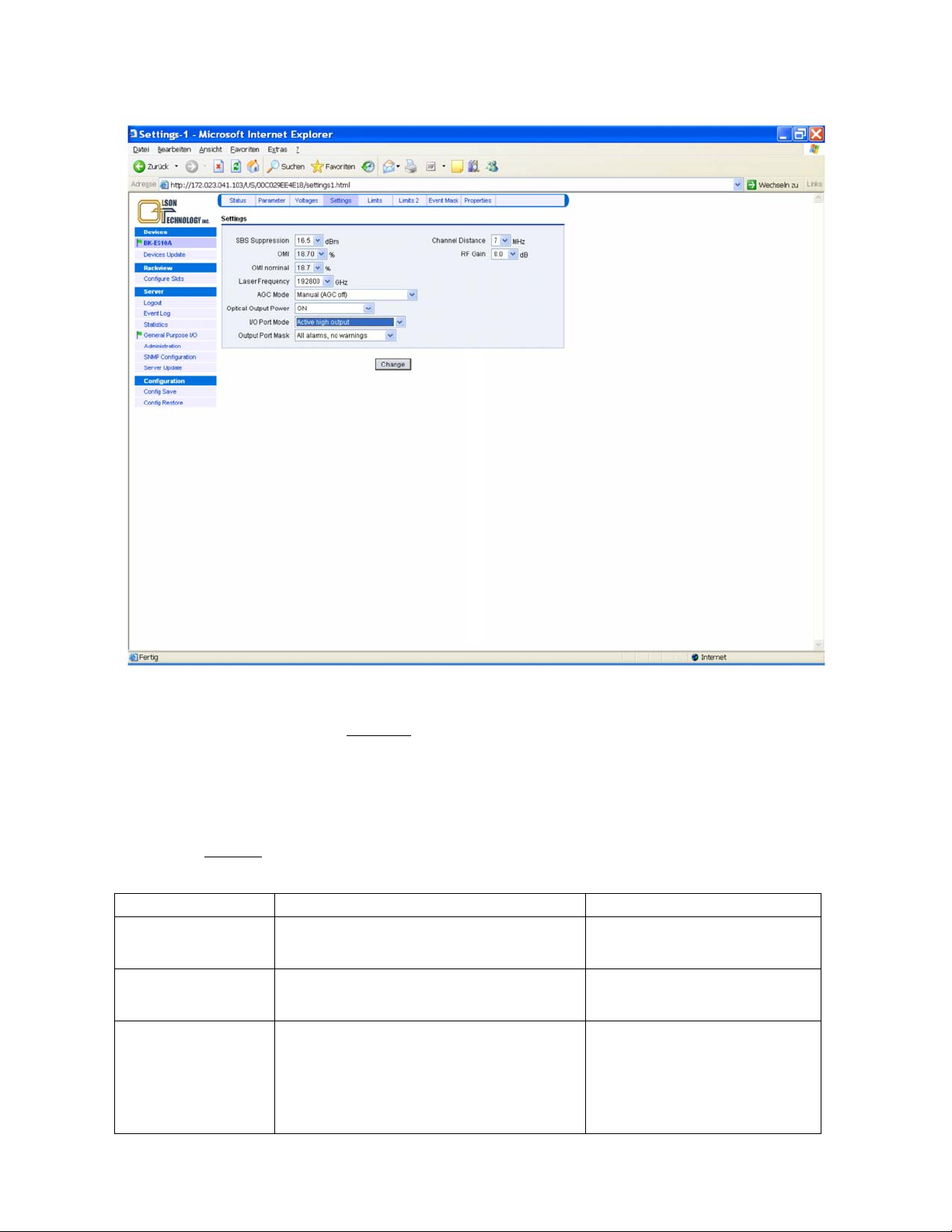
Changing the I/O Port Mode
Figure 47 — Setting the I/O Port Mode of the OTOT-EM55X
This feature is only available from hardware release 2.0 and OTOT-EM55X application software release 2.0. The I/O
port No. 0 can be set either to be an output port
, where 4 modes of operation are available:
• active low
• active high (default = factory setting)
• redundant master (irreversible) or
• redundant master (fallback)
or being an input port
, which implies the redundant slave mode.
The table below shows the mode of operation and the impact on I/O port No. 0.
Mode of operation Description I/O port No. 0
Active low
Active high
(Default = factory setting)
Redundant master (irreversible)
In case of any alarm, which arises in case any of the
alarm thresholds has been reached or due to an internal
error the I/O port becomes low.
In case of any alarm, which arises in case any of the
alarm thresholds has been reached or due to an internal
error the I/O port becomes high.
In case of any alarm, which arises in case any of the
alarm thresholds has been reached or due to an internal
error the I/O port becomes high. In case the alarm condition disappears, the transmitter will remain in the
alarm state until it is reset manually. This mode is implemented to prevent a frequent switching into active/stand-by mode of two redundant transmitters
Output, active low
Output, active high
Output, active high
This port should be connected to the cor-
responding I/O port No. 0 of the redundant transmitter which is set into redundant slave mode.
OTOT-EM55X/XL Optical Transmitter Rev. x1 www.olsontech.com
58
Page 60

Mode of operation Description I/O port No. 0
Redundant master (fallback) In case of any alarm, which arises in case any of the
Redundant slave
alarm thresholds has been reached or due to an internal
error the I/O port becomes high.
In case the alarm condition disappears, the transmitter
will go back into normal operation, which will set the
connected redundant slave mode into stand-by operation.
In case that the input port is low, the transmitter will go
into stand-by operation.
In case that the I/O port No. 0 (input) will become high,
the transmitter will go into normal (nominal) mode.
Output, active high
This port should be connected to the cor-
responding I/O port No. 0 of the redundant transmitter which is set into redundant slave mode.
Input, active high
This port should be connected to the cor-
responding I/O No. 0 port of the redundant transmitter which is set into redundant master mode.
Notes:
The alarm I/O port alarm mask determines whether
• only alarms but no
• alarms and
warnings
warnings (default = factory setting) or
trigger the I/O port No. 0 in output mode.
Application:
Automatic redundancy switching of 2 OTOT-EM55X located side by side:
• Connect a cable between the master and the slave OTOT-EM55X connecting both I/O No.0 ports and GND.
• Use a pull-up of 10kOhms between the I/O port No.0 and +5V
of the slave device (This is only necessary in
DC
hardware rel. 2.0) in order to make sure that the slave OTOT-EM55X will start working if the (both) supply
voltage(s) of the master OTOT-EM55X fail. In hardware release 2.1 and later this pull-up will not be necessary
any more.
• Set the master OTOT-EM55X in one of the two Redundant master modes
• Set the master OTOT-EM55X I/O port mask to the desired mode. Set the slave OTOT-EM55X into the Redun-
dant Slave mode
Observance:
• As long as the master OTOT-EM55X does not show any alarm, the slave OTOT-EM55X should be sleeping (in
stand-by operation), since the I/O port No. 0 level will be in low state.
• If the master alarm faces an alarm situation, it will set the I/O port No. 0 level to high state, therefore awakening
the slave transmitter from sleeping (stand-by mode).
• If the cable between the master OTOT-EM55X and the slave is cut or removed, the slave device will go from
sleeping (stand-by) mode into normal operation due to the internal 100kOhms pull-up resistor.
• If the power supply from the master OTOT-EM55X is removed completely, the slave device will go from
sleeping (stand-by) mode into normal operation immediately. (This situation requires a 10kOhms pull-up at the
side of the slave OTOT-EM55X in hardware release 2.0 as described beyond).
Note:
The slave transmitter might need up to five (5) seconds to provide a high performance output signal, when starting
from stand-by. For that reason, the master transmitter will after an alarm situation create an I/O port high signal to start
the slave transmitter and will, however, operate in normal mode (as far as possible) for five seconds, until it switches
into stand-by mode. The purpose of this method is to make the interruption of the signal as short as possible.
Setting an Alarm/Warning Mask for I/O Port #0
The OTOT-EM55X from NEC appl. SW rel. 1.9.1 allows the user to set an alarm/warning mask, which determines
whether an warning or alarm is shown or suppressed on I/O port #0. The menu is shown in the picture below.
OTOT-EM55X/XL Optical Transmitter Rev. x1 www.olsontech.com
59
Page 61
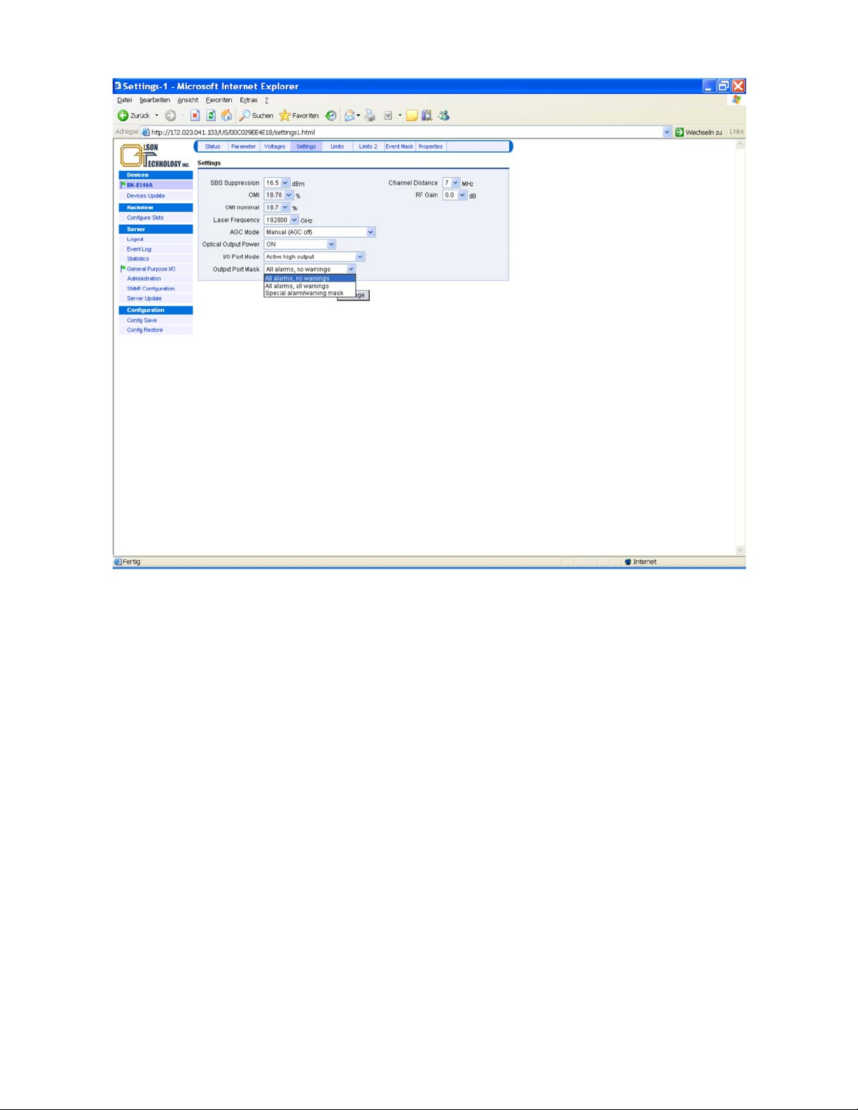
Figure 48 — Setting the Alarm/Warning Mask of the OTOT-EM55X
With this feature all warnings / alarms of the OTOT-EM55X can be either enabled or disabled by the user in relation to
the output #0 port. If the output mask is applied a notify message will be shown on the status menu screen.
OTOT-EM55X/XL Optical Transmitter Rev. x1 www.olsontech.com
60
Page 62
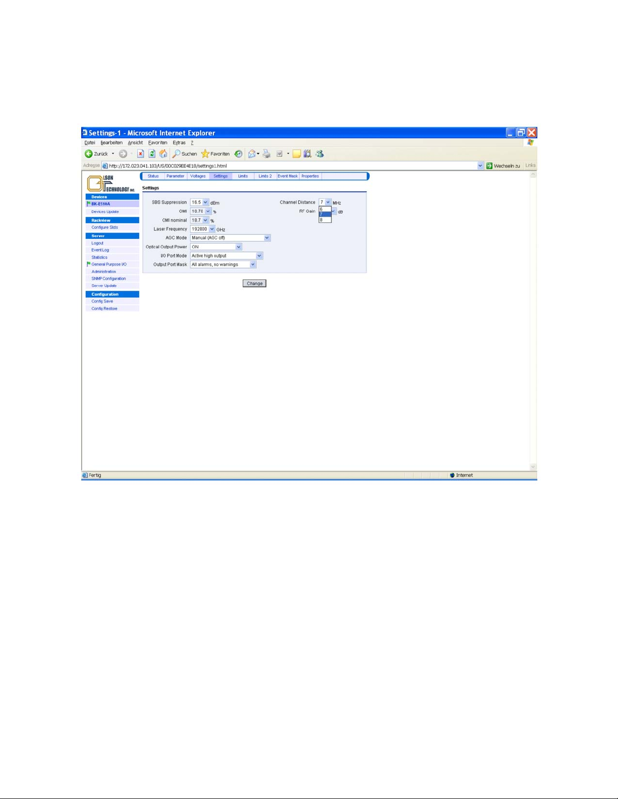
Setting the Channel Spacing of the Transmitted CATV Signal
The OTOT-EM55X provides a unique technology to minimize CSO distortions without requesting pilot tones. By set-
ting the channel spacing to the correct value the CSO control loop will operate with utmost performance. The picture
below shows how to set the channel spacing.
Figure 49 — Setting the Channel Spacing of the OTOT-EM55X
NTSC channel plans in general provide a 6MHz spacing; PAL-D channel plans in general show an 8MHz spacing. In
Europe also 7 MHz spacing is used in some channel plans.
OTOT-EM55X/XL Optical Transmitter Rev. x1 www.olsontech.com
61
Page 63
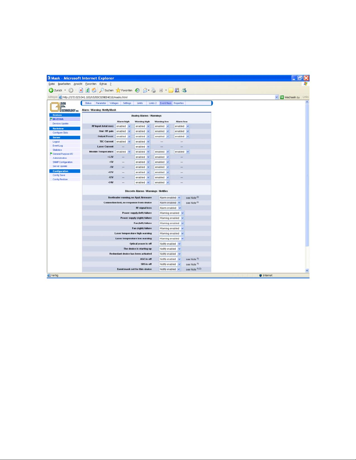
Setting an Event Mask for the Webserver and SNMP Interface
The OTOT-EM55X from NEC appl. SW rel. 1.9.1 allows setting an event mask, which determines whether a warning
or alarm or a notification is shown or suppressed in the Webserver status screen as well as transmitted via the SNMP
interface. The menu is shown in the two following figures.
Figure 50 — Setting the Event Mask for the Webserver and SNMP Interface of OTOT-EM55X
OTOT-EM55X/XL Optical Transmitter Rev. x1 www.olsontech.com
62
Page 64
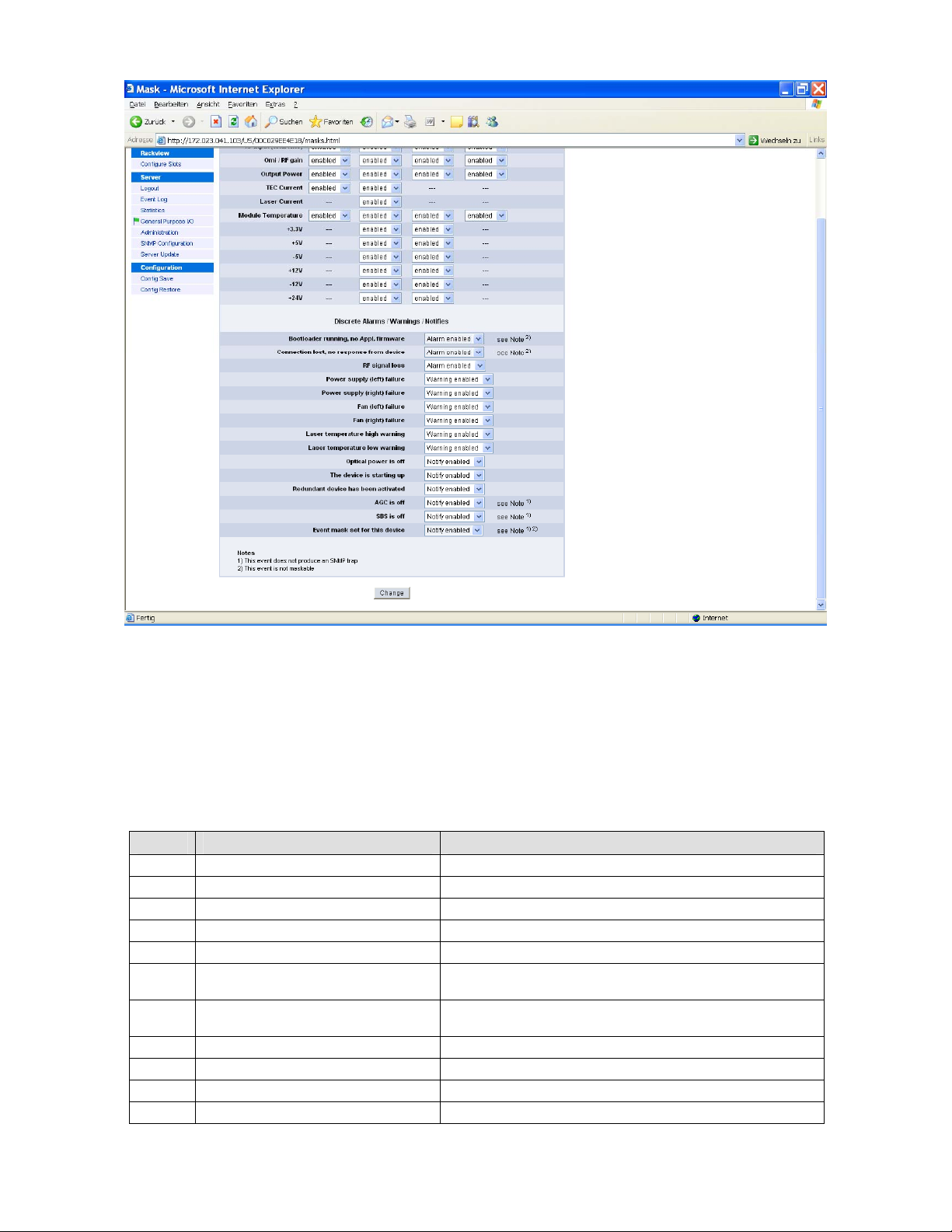
Figure 51 — Setting the Event Mask for the Webserver and SNMP Interface of OTOT-EM55X
With this feature all warnings / alarms of the OTOT-EM55X can be either enabled or disabled by the user in relation to
the LED’s on the front panel, the Webserver status screen and SNMP interface. If the alarm/warning mask is applied a
notify message will be shown on the status menu screen.
Note: If the NEC software of a transmitter is upgraded to Rev. 1.9 or later, the OTOT-EM55X firmware might not sup-
port the alarm/warning flag mask, which means, that the LED’s on the front panel might not reflect the alarm/warning
masks.
Alarm Flags
Index Flag Description
0
TEC_HIGH_ALARM Peltier current is higher than the alarm limit (Laser switched off)
1
OUTPUT_PWR_LOW_ALARM Optical output power is lower than the alarm limit
2
RF_INPUT_LOW_ALARM RF signal is lower than the alarm limit
3
OUTPUT_PWR_HIGH_ALARM Optical output power is higher than the alarm limit
4
RF_INPUT_HIGH_ALARM RF signal is higher than the alarm limit
5 OMI_OR_RFGAIN_LOW_ALARM The calculated RF gain (if AGC on) or the calculated OMI (if AGC
6
OMI_OR_RFGAIN_HIGH_ALARM
...
28
MODULE_TEMP_LOW_ALARM Module temperature is lower than the alarm limit
29 MODULE_TEMP_HIGH_ALARM Module temperature is higher than the alarm limit
30
RESERVED Reserved for the NMS Controller (Do not use these bits)
off) is lower than the alarm limit
The calculated RF gain (AGC on) or the calculated OMI (AGC off) is
higher than the alarm limit
OTOT-EM55X/XL Optical Transmitter Rev. x1 www.olsontech.com
63
Page 65

Index Flag Description
31 RESERVED Reserved for the NMS Controller (Do not use these bits)
Flags in bold letters can be controlled via the limits menu.
Warning Flags
Index Flag Description
0
OUTPUT_PWR_LOW_WARNING Optical output power is lower than the warning limit
1
LASER_HIGH_WARNING The laser current of one laser is higher than the warning limit
2
TEC_HIGH_WARNING The Peltier current of one laser is higher than the warning limit
3
RF_INPUT_LOW_WARNING RF signal is lower than the warning limit
4
POWER_SUPPLY_WARNING One of two power supplies fails (obsolete)
5
FAN_LEFT_WARNING The left fan (looking from device's front side) fails
6
FAN_RIGHT_WARNING The right fan (looking from device's front side) fails
7
OUTPUT_PWR_HIGH_WARNING Optical output power is higher than the warning limit
8
RF_INPUT_HIGH_WARNING RF signal is higher than the warning limit
...
12
13
14
15
16
17
18
19
20
21
22
23
24 -12V_LOW_WARNING Supply -12V is lower than the warning limit
25
26
27
28
29
30
31
POWER_SUPPLY_LEFT_WARNING The left power supplies (looking from device's front side) fails
POWER_SUPPLY_RIGHT_WARNING The right power supplies (looking from device's front side) fails
OMI_OR_RFGAIN_LOW_WARNING
OMI_OR_RFGAIN_HIGH_WARNING
+3.3V_LOW_WARNING Supply +3.3V is lower than the warning limit
+3.3V_HIGH_WARNING Supply +3.3V is higher than the warning limit
+5V_LOW_WARNING Supply +5V is lower than the warning limit
+5V_HIGH_WARNING Supply +5V is higher than the warning limit
-5V_LOW_WARNING Supply -5V is lower than the warning limit
-5V_HIGH_WARNING Supply -5V is higher than the warning limit
+12V_LOW_WARNING Supply +12V is lower than the warning limit
+12V_HIGH_WARNING Supply +12V is higher than the warning limit
-12V_HIGH_WARNING Supply -12V is higher than the warning limit
N/A N/A
N/A N/A
LASER_TEMP_DIFF_LOW_WARNING
LASER_TEMP_DIFF_HIGH_WARNING
MODULE_TEMP_LOW_WARNING Module temperature is lower than the warning limit
MODULE_TEMP_HIGH_WARNING Module temperature is higher than the warning limit
The calculated RF gain (if AGC on) or the calculated OMI (if AGC
off) is lower than the warning limit
The calculated RF gain (AGC on) or the calculated OMI (AGC off) is
higher than the warning limit
Laser temperature difference from nominal value is lower than the
warning limit
Laser temperature difference from nominal value is higher than the
warning limit
Situations triggering a warning flag in the OTOT-EM55X; Flags in bold letters can be controlled via the limits menu.
OTOT-EM55X/XL Optical Transmitter Rev. x1 www.olsontech.com
64
Page 66
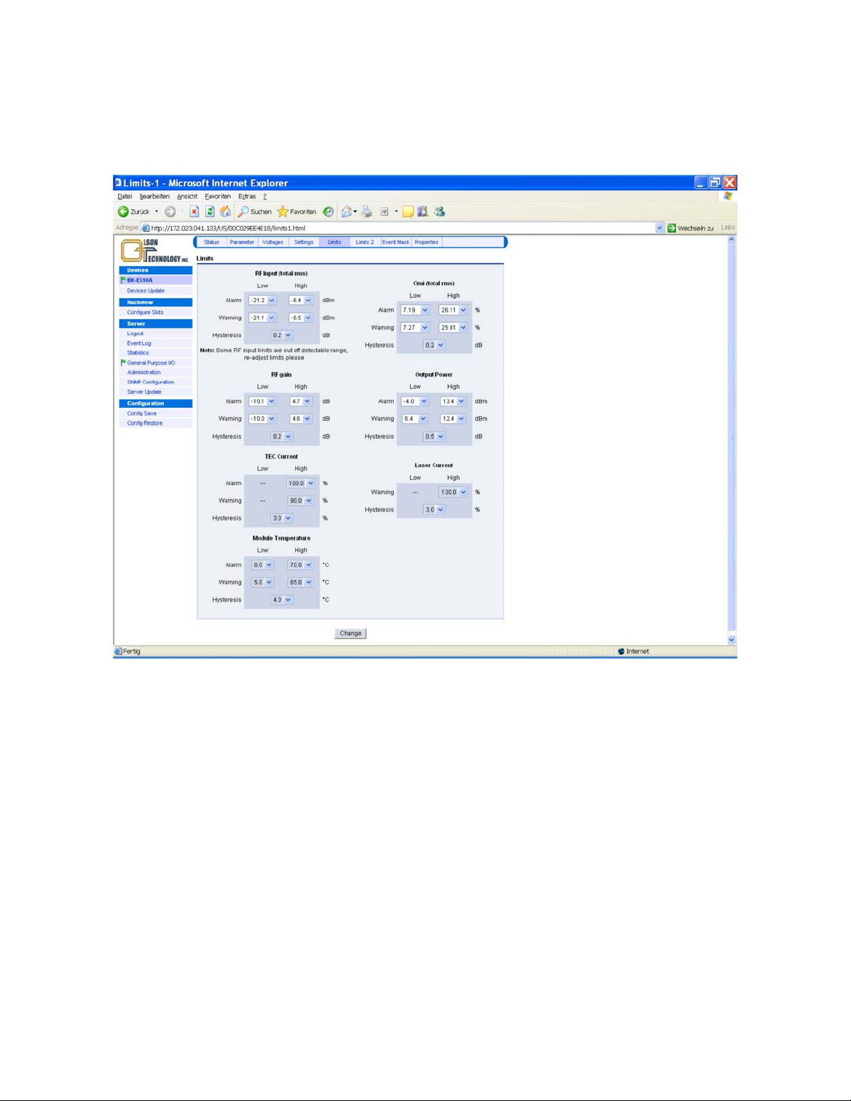
Limits Menus
The two limits menus of the OTOT-EM55X determine, what deviations from the nominal values of some of the oper-
ating conditions of the transmitter lead to either warning or alarm messages. In order to avoid inadequate changes,
some settings are factory settings only.
Figure 52 — Limits Menu of OTOT-EM55X
After successful log-in, the warning and alarm thresholds for the RF RMS input level, OMI total RMS, RF gain and
optical output power can be set by the customer (OTOT-EM55X application software release 2.0 and later). It is rec-
ommended to be very careful in setting the alarm thresholds in order to avoid meaningless alarms, e.g. due to tem-
perature changes etc. For the output power warning a range of at least ±1dB is recommended.
Note:
The settings range for the alarms thresholds for RF input, RF gain and OMI
s might change slightly from device to
totrm
device due to production tolerances.
OTOT-EM55X/XL Optical Transmitter Rev. x1 www.olsontech.com
65
Page 67
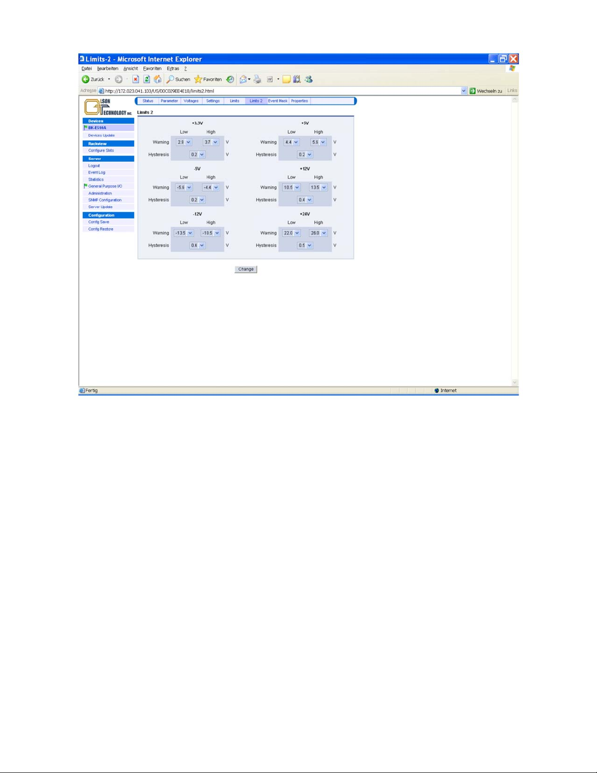
Figure 53 — Limits-2 Menu of OTOT-EM55X
Note: All settings of the limits-2 menu are factory settings only.
OTOT-EM55X/XL Optical Transmitter Rev. x1 www.olsontech.com
66
Page 68
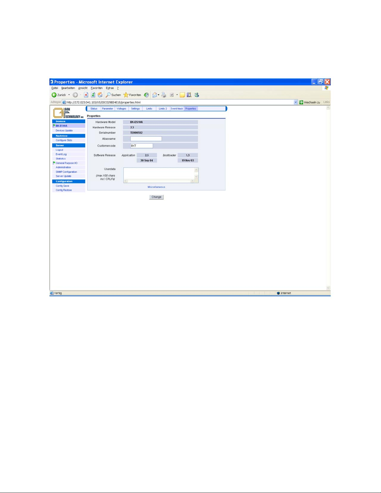
Properties Menu
The properties menu of the OTOT-EM55X provides on overview of the appearance of the transmitter such as hard-
ware model, hardware release, serial number and the software releases. Optionally, an aliasname and some user data
may be edited. The aliasname occurs in the Devices tree of all Webbrowser displays as well as in the LCD.
Figure 54 — Properties Menu of OTOT-EM55X
The miscellaneous button can be used to request either a
• reset to factory settings and cold start
• reset of the transmitter (= cold start)
Note: Be very careful in executing these reset commands since they force cold start situation, where the transmitter
might need about 30 seconds to get back to full performance properties.
Control of Other Devices with the Ethernet Webserver (HTTP) Interface
One of the nice features of the OTOT-EM55X transmitters with embedded SNMP-proxy-agent and Webserver (NEC)
is, that also additional Olson Technology equipment can be managed or monitored through this circuitry either
• via the push-buttons / LCD field of the OTOT-EM55X
• the Webserver (HTTP)
• SNMP interface.
In order to use this function, additional Olson Technology equipment has to be connected to the RS485 (master) inter-
face of the NEC by using a standard RJ-45 patch cable. All Olson Technology subracks provide two RJ-45 sockets lo-
cated on the interface card on the right hand side of the sub rack. Other Olson Technology 19”, 1RU devices (EDFA’s
OTOT-EM55X/XL Optical Transmitter Rev. x1 www.olsontech.com
67
Page 69

and optical switches) provide two RS485 slave interfaces on the rear side of the equipment. The two RS 485 interfaces
are typically used for daisy chaining the RS485 interface bus.
There are some limitations to be considered for a proper functioning of the EMS-server:
• Physical limitations: For the RJ-45 cable a CAT6 or better data cable is recommended. The length of the cable
should be chosen as short as possible. A distance of 10 m should not be exceeded anyway.
• General limitations: A maximum of 48 devices can be managed by one NEC.
• In order to get a correct display of the “rackview” function of the NEC, there are two more limitations required:
• All devices to be managed by one NEC have to be positioned in one rack (and on one side of the rack if the rack
is equipped with equipment from both sides).
• A maximum of four subracks can be used. The address of all subracks have to be set correctly by adjusting the
decimal switches located on the interface panel of the subracks. Address “1” has to be used for the upper sub
rack, the next following sub rack will obtain address “2” and so on.
After powering up, the NEC will poll all equipment connected to the RS485 interface automatically. It might take up
to about 2 minutes until all equipment have been identified. This is also true if equipment is removed or added during
normal operation of the NEC.
Maintenance
• Clean connector ends with a lint free tissue and alcohol before every mating.
• Loose screws fixing the optical connector plate
• Remove the connector from the connector bulkhead.
• Clean the connector ends with a lint-free tissue and alcohol.
• Reinstall the connector into the bulkhead ensuring that the cables/fibers are not stressed.
• Caution: Do not extend the conn ector by more than 1 c m fr om the body of the OTOT-EM55X.
Troubleshooting
To avoid problems with the OTOT-EM55X and 1550nm transmission, follow these general rules:
• Use only carefully cleaned angled connectors like SC/APC, FC/APC, E2000 and similar ones for the whole
transmission system between optical transmitter and receiver. A mix of angled and non angled connectors will
result in high insertion loss, and a degradation of the CSO and CNR performance.
• Avoid bending losses of fibre optic cables. Since optical transmission on 1550 nm significantly more sensitive
to bending losses it is very important to avoid narrow curvatures
• Use a proper levelled, flat RF-input signal. The flatness of the input signal (e.g. ±1 dB) will directly result in the
same variation of CNR, CSO and CTB (in this example: ±1 dB).
• Be careful to understand all nonlinearities in optical fibres with 1550 nm transmission, long distances and high
optical powers. CNR and CSO can easily degraded due to self phase modulation and Brillouin scattering. In
doubts check the performance of the link by using an optical attenuator instead of using optical fibre to see
whether the performance is limited due to impacts from the fibre.
• In case of technical questions please ask our sales representative.
• Note: Since the transmitter is working internally with very high optical power an d micr ow ave s ign al s it is
not admitted to open the transmitter for personal safety and EMC reasons. Do not open the tran smitter!
In case of other than fan/power supply failures the transmitter has to be sent to Olson Technology for
maintenance!
End of Manual
OTOT-EM55X/XL Optical Transmitter Rev. x1 www.olsontech.com
68
 Loading...