

Page 1
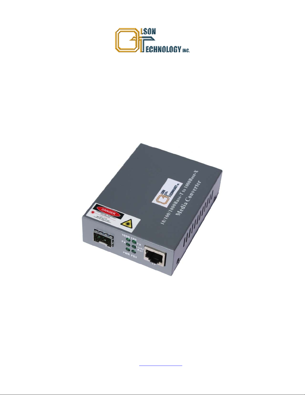
EtherNodePlus Model OTEN-MC-01 Media
Converter, 10/100/1000M, SFP
OPERATING MANUAL
24926 Highway 108
Sierra Village, CA 95346
Phone: (800) 545-1022
Fax: (209 586-1022
025-000501 Rev. X1 E-Mail: [email protected]
10/11/09
Page 2
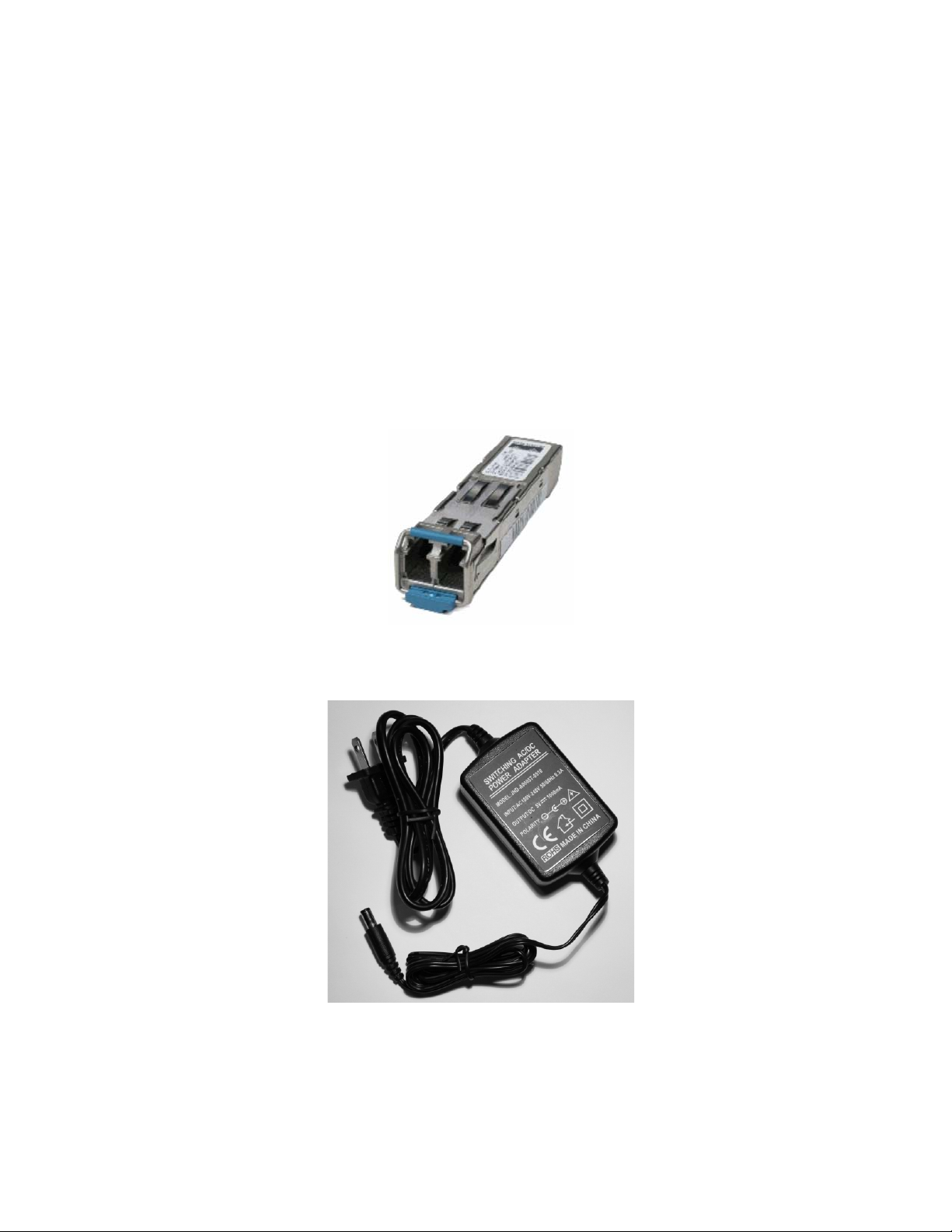
TABLE OF CONTENTS
SAFETY......................................................................................................................................................................3
Safety Precautions..................................................................................................................................................3
Laser Safety Procedure..........................................................................................................................................3
INTRODUCTION........................................................................................................................................................4
PANEL LAYOUT........................................................................................................................................................4
Figure 1 — Converter Front Panel..................................................................................................................4
ETHERNET SPECIFICATIONS.................................................................................................................................4
TYPICAL PERFORMANCE WITH DIFFERENT SFP MODULES ............................................................................5
ELECTRICAL CHARACTERISTICS .........................................................................................................................5
ENVIRONMENTAL CHARACTERISTICS.................................................................................................................5
PHYSICAL CHARACTERISTICS..............................................................................................................................5
INSTALLATION .........................................................................................................................................................5
Typical Mating SFP Module
Typical AC Power Supply (Ships with Unit)
025-000501 Rev. X1 www.olsontech.com
2
Page 3

SAFETY
Safety Precautions
The optical emissions from the units are laser-based and may present eye hazards if improperly used. NEVER USE ANY
KIND OF OPTICAL INSTRUMENT TO VIEW THE OPTICAL OUTPUT OF THE UNIT. Be careful when work-
ing with optical fibers. Fibers can cause painful injury if they penetrate the skin.
Laser Safety Procedure
ALWAYS
read the product data sheet and the laser safety label before powering the product. Note the operation wave-
length, optical output power and safety classifi cat i ons.
If safety goggles or other eye protection are used, be certain that the protection is effective at the wavelength emitted by
the device under test BEFORE
ALWAYS
connect a fiber to the output of the device BEFORE power is applied. Power should never be applied without
applying power.
an attached fiber. If the device has a connector output, a connector should be attached that is connected to a fiber. This
will ensure that all light is confined within the fiber waveguide, virtually eliminating all potential hazard.
NEVER
look at the end of the fiber to see if light is coming out. NEVER! Most fiber optic laser wavelengths (1310nm
and1550nm) are totally invisible to the unaided eye and will cause permanent damage. Shorter wavelengths lasers (e.g.,
780nm) are visible and are very damaging. Always use instruments, such as an optical power meter, to verify light output.
NEVER, NEVER, NEVER
includes microscopes, eye loupes and magnifying glasses. This WILL
look into the end of a fiber on a powered device with ANY sort of magnifying device. This
cause a permanent and irreversible burn on your
retina. Always double check that power is disconnected before using such devices. If possible, completely disconnect the
unit from any power source.
If you have questions about laser safety procedures, please call Olson Technology before powering your product.
025-000501 Rev. X1 www.olsontech.com
3
Page 4
INTRODUCTION
The OLSON TECHNOLOGY, INC. Model OTEN-MC-01 EtherNodePlus Media Converter, 10/100/1000Mb/s allows
network operators to convert signals between an electrical Ethernet 10/100/1000Mb/s UTP interface and an optical interface. The traditional 10/100/1000Mb/s gigabit Ethernet can be extended to the distance of 80+km through a fiber optic
link.
The OTEN-MC-01 incorporates the latest gigabit IC technology. Indicator LED’s on the front panel allow the unit’s
status to be fully monitored, simplifying installation and maintaining network performance.
PANEL LAYOUT
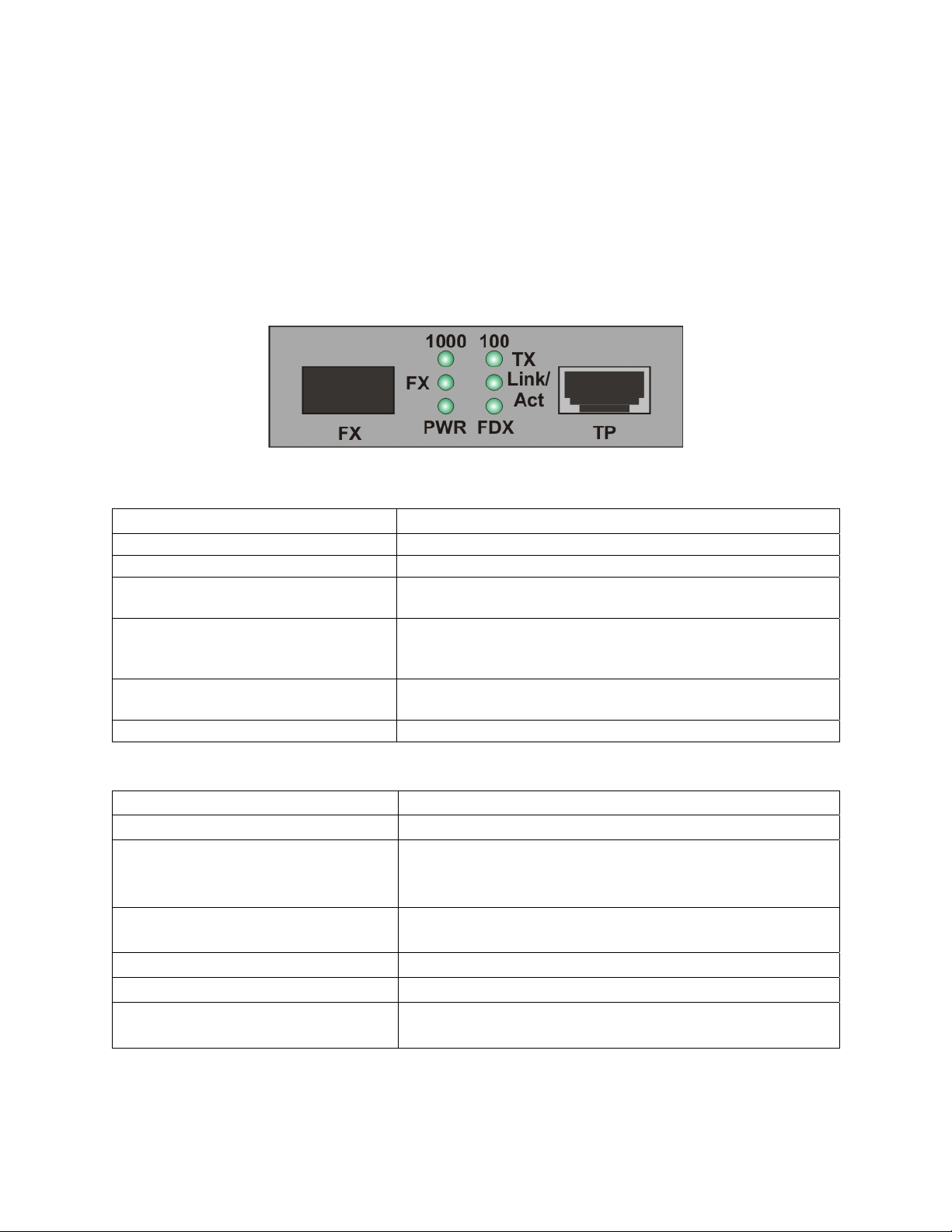
Figure 1 — Converter Front Panel
The table below describes the LED indicator functions.
Designation Meaning
100 Lit when TP speed is 100Mb/s.
1000 Lit when TP speed is 1000Mb/s.
Link/Act
FDX
FX
PWR Lit when the unit is receiving power.
Lit when the TP connection is good.
Blinks when collision signal is present.
Lit when TP full-duplex mode is active.
OFF when TP half-duplex mode is active.
Blinks when collision signal is present.
Lit when TP connection is good.
Blinks when TP is transmitting data.
ETHERNET SPECIFICATIONS
Parameter Specification
Standards IEE802.3z/AB, 10/100/1000Base-T and 1000Base-SX/LX/HX
Cables UTP Category 5e or Category 6 (100m max. distance)
50/125µm Multimode Fiber (500m max. distance)
9/125µm Single-mode Fiber (80+km max. distance)
Connectors UTP: RJ-45, 10/100/1000Mb/s
Optical: SFP Module
Mac Add. Table 4K
Data Buffer 256K
Flow Control Full-duplex IEEE802.3x
Half-duplex Back Pressure
025-000501 Rev. X1 www.olsontech.com
4
Page 5

TYPICAL PERFORMANCE WITH DIFFERENT SFP MODULES
Fiber Type Max. Distance Wavelength Tx Power Sensitivity Link Budget
50µm Multimode
Single-mode
Single-mode
550m 850nm -11 to -6dBm <-18dBm
30km 1310nm -8 to 0dBm <-25dBm
80km 1550nm, CWDM -5 to 0dBm -25dBm
7dBm
17dBm
20dBm
ELECTRICAL CHARACTERISTICS
Min. Typ. Max. Units
Converter Power Requirements (See Note 1)
Power Supply Voltage
Note 1) Using Model OTOLS-1312-30 SFP module.
5 Volts DC
270 mA
100 240 Volts AC
50 60 Hz
ENVIRONMENTAL CHARACTERISTICS
Min. Typ. Max. Units
Operating Temperature Range
Storage Temperature Range
Humidity, RH, non-condensing
0 +50 °C
-20 +70 °C
5 90 %
PHYSICAL CHARACTERISTICS
Min. Typ. Max. Units
Weight
Weight with 2 SFP Modules
Dimensions
6.4 oz.
180 g
6.9 oz.
195 g
1.02 x 2.75 x 3.66 in.
26 x 70 x 93 mm
INSTALLATION
1. Insert an SFP module into the SFP cage on the converter.
2. Attach a fiber cable from the SFP on the converter to the fiber network. The fiber connections must match: transmit
socket to receive socket.
3. Attach a UTP cable from the TP network device to the RJ45 port on the converter.
4. Connect the power cord to the converter and check that th e Power LED lights up. The TP Act and FX Act LEDs will
light when all the cable connections are satisfactory.
025-000501 Rev. X1 www.olsontech.com
5
 Loading...