

Page 1

LP-OT-10-RCxx
HIGH POWER CWDM
RETURN LASER TRANSMITTER
INSTRUCTION MANUAL
Phone:
E-Mail: [email protected]
025-370503 REV X1 04-10-07
(209) 586-1022
(800) 545-1022
Fax:
(209) 586-1026
www.olsontech.com
Page 2

TABLE OF CONTENTS
SPECIFICATIONS Page 3
SAFETY WARNINGS Page 4
INTRODUCTION Page 5
INSTALLATION Page 5
Environmental Considerations Page 5
Optical Connectors and Cleaning Page 5
External Controls and Test Points Page 5
RF Input Page 6
Indicators and Test Points Page 7
025-370503 REV X1
Page 2 of 7
Page 3

LP-OT-10-RCxx - Specifications
RF INPUT & PERFORMANCE PARAMETERS:
Frequency Range 5 MHz to 300 MHz
Frequency Response +/- 1.0 dB
Input Impedance 75 ohms
Input Return Loss > 16 dB
Input Level for Optimum Performance +15 to +19 dBmV with 4dB adjustable front panel attenuator (max loading)
Input Slope 0 dB
Noise Power Ratio (NPR) 15 dB dynamic range @ 41dB threshhold
OPTICAL PARAMETERS:
Center Wavelength(s) (+/- 3 nm) ITU-Grid: 1470, 1490, 1510, 1530, 1550, 1570, 1590 and 1610 nm
Output Powers 10dBm/10mW
Laser Type Cooled, Isolated DFB (optimized for return path band)
ELECTRICAL, ENVIRONMENTAL & MECHANICAL PARAMETERS:
Dimensions 4.5" H x 1.125" W x 8.75" D (11.4 cm x 2.9 cm x 22.2 cm)
Weight 1 lb. (.454 kg)
Operating Temperature Range 0 degrees C to +50 degrees C (+32 to +122 degrees F)
(Air temperature measured at air inlet of Model LP-CH chassis)
Humidity Range to 95% non-condensing
(Recommended for use only in non-condensing environments)
Mounting In applications slot in Model LP-CH-16 LaserPlus Chassis
Module Slots One slot width: Slot# 1-15 (inclusive)
Powering 5.25VDC per module
Protection 3A SB fuse [Littelfuse PN# 0454033; Olson PN# 286-000009]
TRANSMITTER INTERFACES:
RF Input Connector F-Type (rear of module)
RF Input Test Point (F-Type Connector) +10dBmV/carrier @ 25MHz for optimal OMI & performance
Input Level Adjust Range 4dB via variable attenuator (front of module)
Optical Output Connector SC/APC standard; FC/APC optional (front of module)
LED Indicators (Green/Red) Optical Power Alarm; Laser Current Alarm; Cooler Alarm
025-370503 REV X1
Page 3 of 7
Page 4

SAFETY WARNINGS
LASER RADIATION
The LP-OT Series laser transmitter emits invisible laser radiation that can
cause permanent eye damage. AVOID DIRECT EXPOSURE TO
BEAM. Operate the transmitter only with the proper optical fiber installed
in the transmitter optical connector. Power to the LP-OT Series
should be turned-off or preferably, disconnected whenever the optical connector cover is opened and there is no
installed fiber (as when the fiber connector is being installed or removed from the transmitter connector).
NEVER USE ANY OPTICAL INSTRUMENT TO VIEW THE OUTPUT OF THE LASER
TRANSMITTER. “OPTICAL INSTRUMENT” INCLUDES MAGNIFYING GLASSES,
OPTICAL FIBER SCOPES, etc.
NEVER LOOK INTO THE OUTPUT OF THE LASER TRANSMITTER.
NEVER LOOK INTO THE OUTPUT OF A FIBER CONNECTED TO A LASER
TRANSMITTER.
NEVER LOOK INTO OR USE ANY OPTICAL INSTRUMENT TO VIEW THE DISTANT
END OF A FIBER THAT MAY BE CONNECTED DIRECTLY OR VIA AN OPTICAL SPLIT,
TO A TRANSMITTER THAT MAY BE OPERATING. THIS SPECIFICALLY APPLIES TO
FIBERS THAT ARE TO BE CONNECTED TO RECEIVERS (SUCH AS THE OTOR-300) OR
OTHER DEVICES AT ANY DISTANCE FROM THE LASER TRANSMITTER.
HIGH VOLTAGE
The AC power supply for the Laser Plus Chassis contains no internal user serviceable parts. There is
exposed high voltage inside the supply. The power supply housing should be opened only by factory service
technicians.
FIRE HAZARD
The AC input rear power supply fuse is a 3AG, 3.25A, slow blow fuse. To avoid a risk of fire, this fuse
should be replaced only with an identically rated fuse.
025-370503 REV X1
Page 4 of 7
Page 5

INTRODUCTION
The Olson Technology, Inc. Model LP-OT-10-RCxx 1550nm CWDM Return Path Transmitter is a
single-slot module for the LaserPlus optical transmission platform. It is engineered to meet both today’s and
tomorrow’s advanced requirements for return path transmission of advanced upstream applications, with an optical
loss budget to 14dB (>60km) when an 8 wavelength CWDM system is deployed. With an NPR value of 40 dB
over a dynamic range of 15 dB (higher than other vendors with NPRs from 40/10 dB to 35/13 dB), this transmitter
ensures error-free transport of all current return path services (QPSK & 16/64 QAM –requires NPR > 30 dB), as
well as future return path services utilizing sophisticated “HI-PHY” modulation schemes (ODFM & 256 QAM requires NPR of 40 dB). The rugged, low-profile, amplitude-modulated Model LP-OT-10-RCxx transmitter
utilizes a high-quality, optically isolated, cooled 1550 nm CWDM laser with an optical output power of 10 mW .
ENVIRONMENTAL CONSIDERATIONS
The LP-OT is specified to operate from 0°C to +50°C. It will probably not require an air-conditioned
environment. It should be mounted in an adequately ventilated area. Like any other electronic equipment, it will
probably have a longer life span if it is not operated at the upper limit of the temperature range. Installation in wet
areas or areas of extremely high humidity should be avoided. Extremely dirty or dusty areas should be avoided if
possible. Objects or debris should not be allowed to block the openings in the LP-OT or LP-CH-16 housing or
fan.
OPTICAL CONNECTORS AND CLEANING
The fiber ends can be damaged by the insertion of contaminated connectors. Some types of customer
damage to connectors are not covered under warranty. Fiber connectors should never be left uncovered.
Prepackaged alcohol wipes are the most convenient means of cleaning optical connectors. Clean alcohol and lint
free wipes or swabs may also be used.
EXTERNAL CONTROLS AND TEST POINTS
The LP-OT has two external DC test points. One reads laser current at 1V per 50mA. A typical laser
current of 25mA would read 0.5V at this test point. The laser power test point is 0.1V per mW. This is for
historical tracking. The optical power meter is a much more accurate means of measuring power. Both of these test
points should be measured with a high impedance voltmeter.
025-370503 REV X1
Page 5 of 7
Page 6
RF INPUT
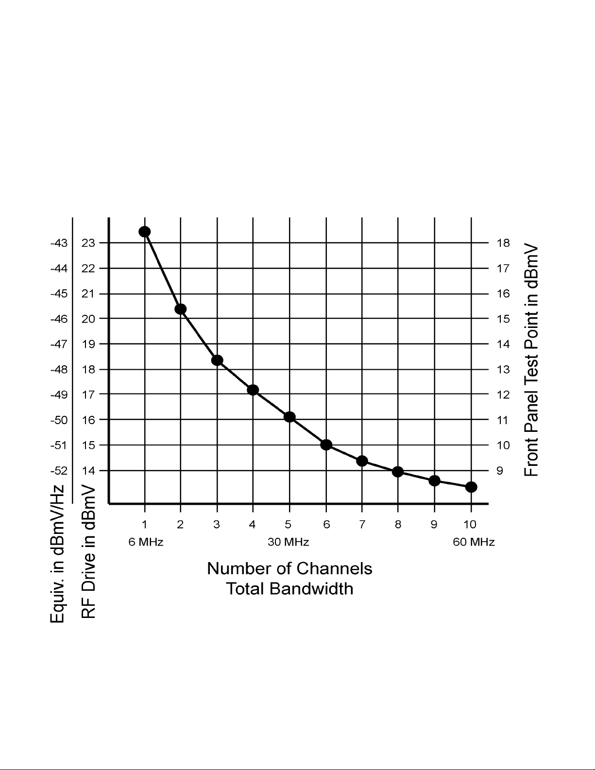
The optimum RF input level for the LP-OT-10-RCxx is 15dBmV per channel with a standard loading of six
CW channels. The chart below shows the change in RF input level according to the amount and type of channel
loading. The chart shows on the right what the RF input level is according to the front panel test point. On the left,
the drive level (RF Input) in dBmV is shown, along with the equivalent dBmV/Hz measurement for use with digital
loading. If loading with data channels only (QPSK, QAM) refer to the amount of total bandwidth the data channels
are consuming. 15dBmV per CW channel is equivalent to 51dBmV/Hz. To easily set the input level without a
power meter, the front panel +10dB test point may be used.
Page 6 of 7025-370503 REV X1
Page 7
INDICATORS AND TEST POINTS FOR LP-OT-10-RCxx
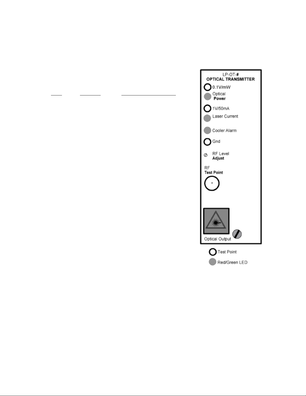
The laser transmitter has front panel test points for optical power and laser current. Only a high impedance
voltmeter should be used. The meter common should be connected to the module ground test point, not to chassis
ground.
The optical power alarm LED is normally green. It turns red
on insufficient optical power. Optical ouput reads as shown below:
UNIT OUTPUT TEST POINT VOLTAGE
LP-OT-10-RCxx 10.00mW 1.00V
The laser current alarm LED is normally green. It turns red
on excessive laser current. At a typical laser current of 50mA the TP
will read 1.0V.
The cooler alarm LED is normally green. It turns red when
the cooler cannot keep the laser at a constant temperature.
The RF level adjust control allows for a 4dB range of input
level adjustment.
The RF test point is calibrated to read +10dBmV @ 25MHz
for proper laser modulation with 6 channel loading. This level will
change with channel loading. It does not require termination.
The optical output connector is type SC/APC, with optional
FC/APC connector available.
Page 7 of 7025-370503 REV X1
 Loading...