

Page 1

LCP-500-550
TELEVISION PROCESSOR
INSTRUCTION MANUAL
Phone:
E-Mail: [email protected]
025-000235 REV C 5/8/02
(209) 586-1022
(800) 545-1022
Fax:
(209) 586-1026
www.olsontech.com
Page 2
1) INTRODUCTION
The Olson T echnology LCP-500-550 is a frequency agile F .C.C. compatible television processor that will
select any VHF , standard and HRC cable, or UHF input channel in 0.25MHz increments, from channel 2
(54MHz) to channel W (300MHz) and UHF channel 14 (471.25MHz) through channel 83 (885.25MHz).
This unit provides >+55dBmV output in 1MHz increments, on any channel from channel 2 (55.25MHz)
through channel AAA (547.25MHz). All input and output channels are selectable by front panel DIP switches.
A front panel control allows adjustment of the output frequency for F.C.C. required of fsets.
The LCP-500-550 uses dual SA W filtering for excellent adjacent channel performance and has >-60dB
spurious free output capability . The LCP-500-550 also offers >77dB out-of-band carrier to noise perfor mance which will allow virtually unlimited numbers of LCP-500-550’s to be combined without the use of
external band pass filters. Power consumption is 14 watts maximum @ 115 VAC.
2) INPUT CHANNEL SELECTION
LCP-500-550
TELEVISION PROCESSOR
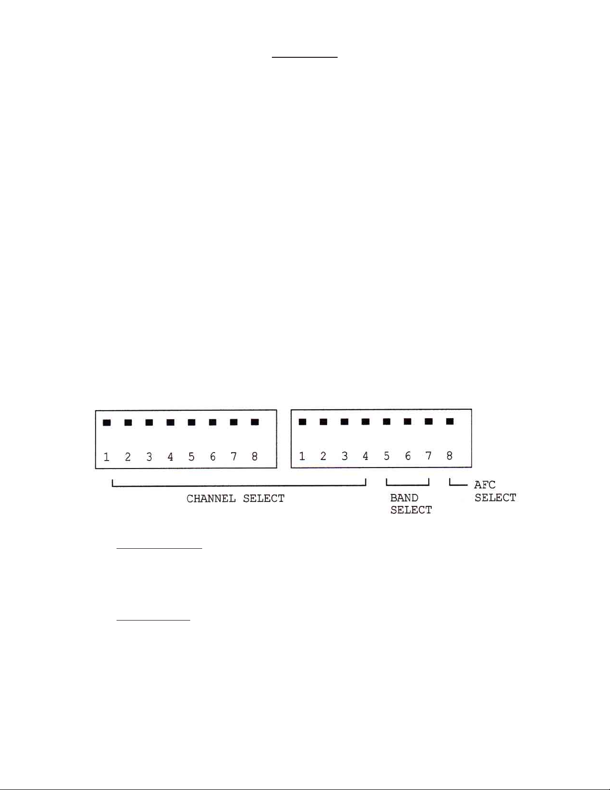
Remove the small cover plate from the front panel to expose the 2, 8 position channel select, band select,
and AFC select DIP switches as shown in Figure 1.
FIGURE 1 - Input Channel Select
A) Channel Selection: Channel selection is accomplished by properly setting the 8 positions on DIP
Switch #1 and the first 4 positions on DIP Switch #2 to the corresponding channel codes. Channel
codes can be selected from the code cards attached to the “Input Channel Select” cover plate, or
from Figure #2 of this manual.
B) Band Selection: The proper band is selected by setting positions 5, 6 & 7 on DIP Switch #2 to the
corresponding band. The correct position for these switches can be selected from the code card
attached to the “Input Channel Select” cover or from Figure 2.
025-000235 REV C
Page 2
Page 3

HRC CA TV CHANNEL CODES
CHANNEL
10
11
12
13
14
15
16
17
18
19
20
VIDEO FREQ.
2
3
4
5
6
7
8
9
54.000
60.000
66.000
72.000
78.000
174.000
180.000
186.000
192.000
198.000
204.000
210.000
120.000
126.000
132.000
138.000
144.000
150.000
156.000
DIP SWITCH
1111 0001
1110 0101
1111 1101
1110 1011
1111 0111
1111 0110
1110 0001
1111 1001
1110 1101
1111 1101
1110 0111
1111 1111
1110 1001
1111 0101
1110 0011
1111 1011
1110 1111
1111 0000
1110 0100
LSB = LEFT
1000 0000
1000 0000
1000 0000
1000 0000
1000 0000
1100 0000
1100 0000
1100 0000
1100 0000
1100 0000
1100 0000
1100 0000
0100 0000
0100 0000
0100 0000
0100 0000
0100 0000
1100 0000
1100 0000
21
22
23
24
25
26
27
28
29
30
31
32
33
34
35
36
37
66
67
68
69
62.000
168.000
216.000
222.000
228.000
234.000
240.000
246.000
252.000
258.000
264.000
270.000
276.000
282.000
288.000
294.000
300.000
474.000
480.000
486.000
492.000
1111 1100
1110 1010
1110 1000
1111 0100
1110 0010
1111 1010
1110 1110
1111 0001
1110 0101
1111 1101
1110 1011
1111 0111
1110 0000
1111 1000
1110 1100
1111 0010
1110 0110
1111 1000
1110 1100
1111 0010
1110 0110
1100 0000
1100 0000
0010 0000
0010 0000
0010 0000
0010 0000
0010 0000
0010 0000
0010 0000
0010 0000
0010 0000
0010 0000
1010 0000
1010 0000
1010 0000
1010 0000
1010 0000
0001 0000
0001 0000
0001 0000
0001 0000
025-000235 REV C
95
96
97
98
99
90.000
96.000
102.000
108.000
114.000
1111 1000
1110 1100
1111 0010
1110 0110
1111 1110
0100 0000
0100 0000
0100 0000
0100 0000
0100 0000
Page 3
Page 4
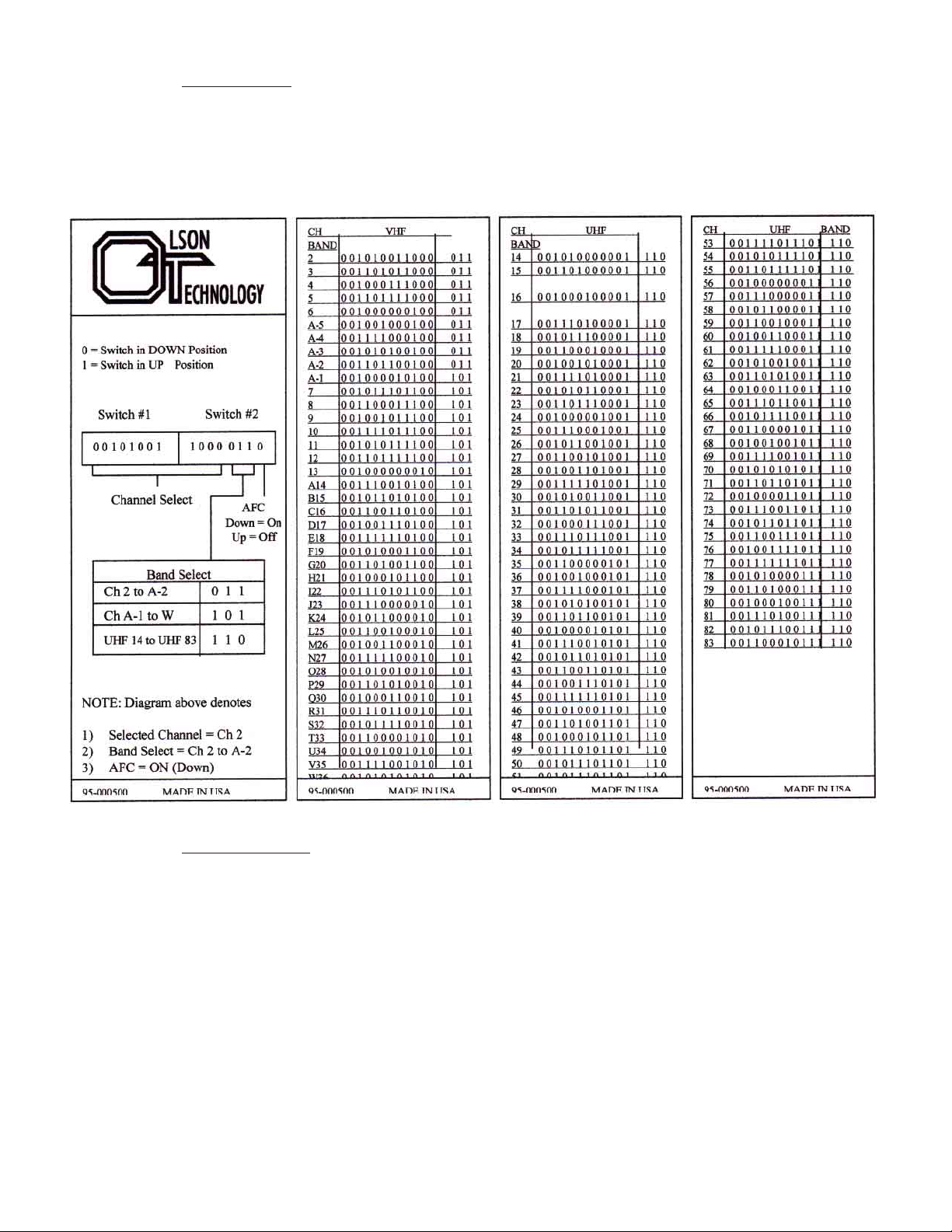
C) AFC Selection: Most off-air TV stations are usually very close to the specified carrier frequency
such that the AFC function need not be used. However , if AFC is desired, then utilize position 8 on
DIP Switch #2. Refer to Figure #2.
FIGURE 2 - Input Channel Select Chart
D) Input Connection: After an input channel and the band select have been determined and the DIP
switches placed in the correct position, connect an antenna or cable source to the appropriate RF
input connector. For optimum video quality the input signal level should be a minimum of
+10dBmV . This unit will function with input signal levels as low as -20dBmV , but any signals below
-20dBmV will be squelched by the internal squelch circuit.
3) AGC ADJUSTMENT
A) The delayed AGC adjustment is factory set for a +5 to +10dBmV threshold. This setting provides
for the best signal-to-noise ratio for low level off-air signals.
B) For cable operation, where high-level adjacent channel signals may be present, adjacent channel
performance may be improved by lowering the AGC threshold level.
025-000235 REV C
Page 4
Page 5
C) T o adjust the delayed AGC threshold level for cable operation.
1. Connect a cable signal carrying three adjacent channels at a level of +15dBmV maximum to
the RF input connector.
2. Set the input channel and band select DIP switches to the channel located in the center carrier
frequency (of the three channels).
3. Adjust the demodulator delayed AGC control (R32) slightly for the least amount of adjacent
channel interference while viewing the picture on a video monitor or through a modulator .
4) OUTPUT CHANNEL SELECTION
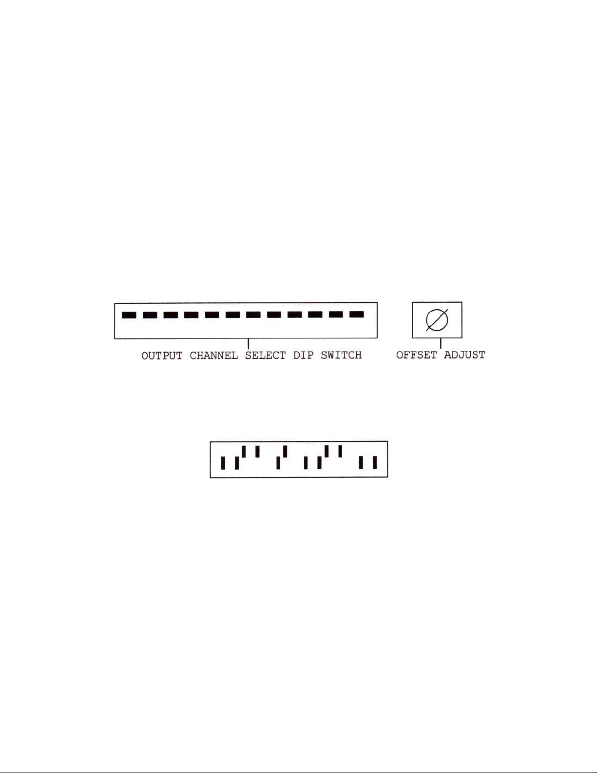
Remove the small cover plate from the front panel to expose the channel select switches and the F .C.C.
offset adjust control as shown in Figure 3.
FIGURE 3 - Output Channel Select/Offset Adjust
Channel selection is made by properly setting the 12-position DIP switches to the corresponding channel
code. Channel codes are shown in T able 1 and on the code card attached to the cover plate. Set the DIP
switches from left to right. For example, if channel 11 is desired, its corresponding channel code is:
025-000235 REV C
Page 5
Page 6
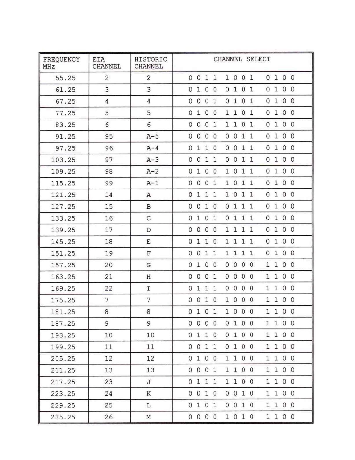
T able 1
LCP-500-550
ST ANDARD TV CHANNEL CODES FOR OUTPUT
025-000235 REV C
Page 6
Page 7
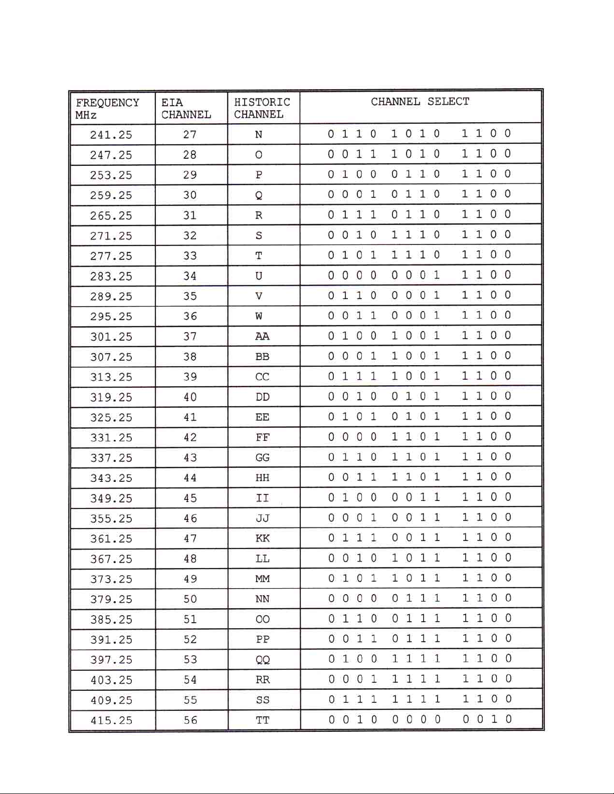
T able 1 (Continued)
LCP-500-550
ST ANDARD TV CHANNEL CODES FOR OUTPUT
025-000235 REV C
Page 7
Page 8
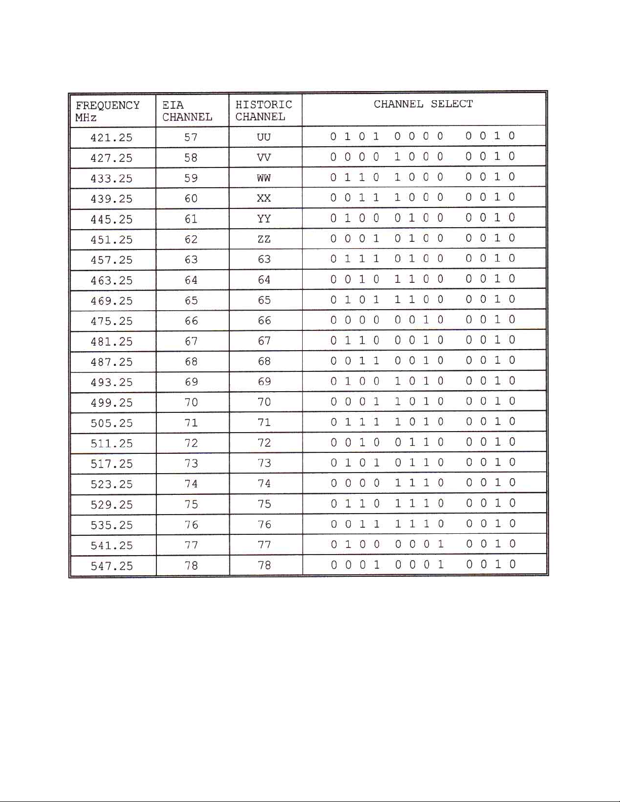
T able 1 (Continued)
LCP-500-550
ST ANDARD TV CHANNEL CODES FOR OUTPUT
025-000235 REV C
Page 8
Page 9
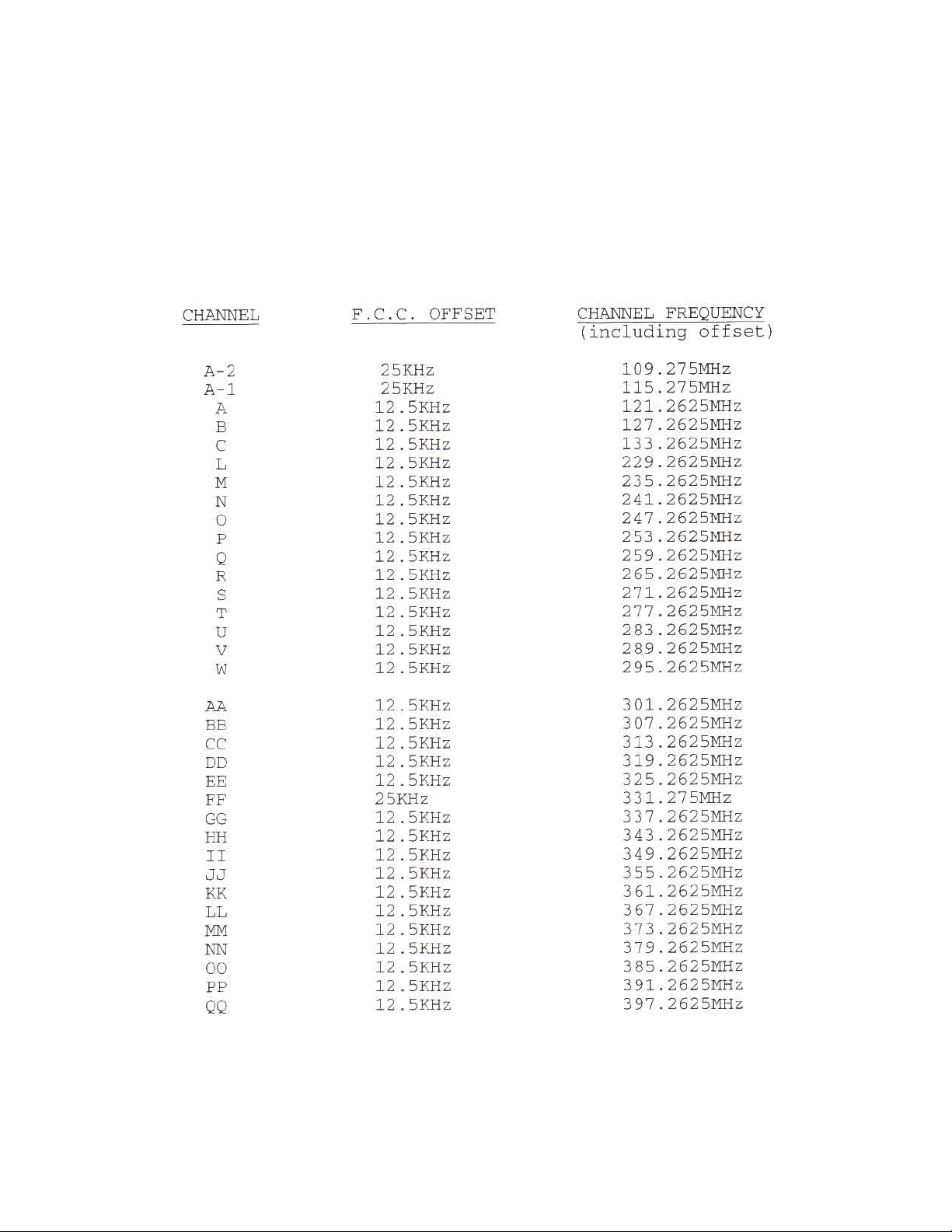
5) F .C.C. OFFSET ADJUSTMENT
F .C.C. offset frequencies are shown in T able 2 and summarized on the card attached to the cover plate. T o
adjust the frequency of a particular channel to provide the correct F .C.C. offset, look up it’ s offset fre
quency in T able 2 (or use the summary attached to the cover plate). Connect a frequency counter to the RF
output and remove the input signal from the LCP-500-550. Adjust the of fset control (located to the right of
the DIP switch) so that the counter reads the correct frequency .
T able 2. F .C.C. Offset Frequencies
025-000235 REV B
Page 9
Page 10

6) RF OUTPUT AND AURAL CARRIER LEVEL ADJUSTMENT
A) Using a field strength meter or spectrum analyzer, set the video carrier to the desired level with the RF
output level control (typically +55dBmV).
B) T une to the aural carrier, which is located 4.5mHz above the video carrier .
C) Adjust the aural carrier level control (A/V) to the desired level, typically 15dB below the video carrier .
CAUTION: Reducing the visual/aural carrier ratio to less than 15dB can result in high spurious signals
in adjacent channels.
D) Output Connection - The output signal is now present at the RF output port.
7) MISCELLANEOUS
A) The LCP-500-550 is BTSC compatible. The unit will automatically function with either stereo or
monaural audio carriers and will pass an SAP signal if present.
B) The LCP-500-550 is equipped with a 0.5A slo-blo fuse. For safety , and to maintain proper perfor-
mance of the unit, please replace only with an equivalent fuse.
C) When installing the LCP-500-550 in an equipment rack, it is best to leave an empty rack space
above and below the unit to allow for optimum air circulation.
025-000235 REV C
Page 10
 Loading...