

Page 1
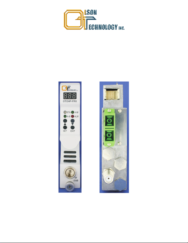
OPTICAL HEADEND PLATFORM
OTOHP-FRX FORWARD RECEIVER WITH REDUNDANT
INPUTS
INSTRUCTION MANUAL
Phone: (209) 586-1022
(800) 545-1022
Fax: (209) 586-1026
E-Mail: [email protected]
OTOHP-FRX Rev. X1 11/16/2010
www.olsontech.com
Page 2

SAFETY WARNINGS
LASER RADIATION
The optical fiber jumper attached to the OTOHP-FRX receiver carries invisible radiation that can
cause permanent eye damage. . Operate the receiver
only with the proper optical fiber installed in the receiver optical connector. Power to the receiver
should be turned-off or preferably, disconnected whenever the optical connector cover is opened
and there is no installed fiber (as when the fiber connector is being installed or removed from the
transmitter connector).
NEVER
USEANYOPTICALINSTRUMENT TOVIEWTHEOUTPUTOFTHE OPTICALFIBER
OR CONNECTOR “OPTICAL INSTRUMENT” INCLUDESMAGNIFYINGGLASSES,ETC.
NEVER
LOOK INTO THE OUTPUT OF THE CONNECTOR TO BE ATTACHED TO THE
RECEIVER
NEVER
LOOK INTO THE OUTPUT OF A FIBER CONNECTED TOA LASER
TRANSMITTER.
NEVER
LOOK INTO OR USE ANY OPTICAL INSTRUMENT TO VIEW THE DISTANT END
OF A FIBER THAT MAY BE CONNECTED DIRECTLY OR VIAAN OPTICAL SPLIT, TO A
TRANSMITTER THAT MAY BE OPERATING. THIS SPECIFICALLYAPPLIES TO FIBERS
THATARE TO BE CONNECTED TO RECEIVERS OR OTHER DEVICES ATANY
DISTANCE FROM THE LASER TRANSMITTER.
AVOID DIRECT EXPOSURE TO BEAM
PRECAUTIONS
Failure to comply with these general safety precautions and with the specific precautions
described elsewhere in this manual violatesthe safetystandards ofthe design manufacture and
intended use of the device Olson Technology Inc assumes noliability for thecustomer's failure to
comply with these precautions.
Do not operate the receiver outside of its ratings. Doing so may result in unsatisfactory
performance, receiver failure, shortened receiver life span, or a safety hazard.
Do not attempt to modify or service any part of a receiver module. Doing so voids the warranty.
Contact Olson for an RMA number and Return the unit to Olson Technology Inc. for service and
repair.
Do not restrict airflow in front of or behind the chassis. The receiver should be operated in an
ambient environment between 0 and 50ºC (32 and 122ºF).
Store the module awayfrom corrosivematerials,at a temperature between -40 and +70ºC (-40 and
+158ºF), and with no more than 85% humidity,non-condensing.
..
,,
Page 3
INTRODUCTION
The Olson Technology, Inc. Model OTOHP-FRX is a High-performance forward
receiver with dual redundant optical inputs for maximum reliability.The SC/APCoptical
inputs are referredtoas Port 1 andPort2. Port 1is the primary optical input Port 2isthe
.
backup optical input. The OTOHP-FRX receiver is designed to operate with Olson
Technology’s OHP ( ptical eadend latform) series of products. Internal RF
OH P
attenuators can be used in manual orAGC mode to adjust the RF output over a 20dB
range. The OTOHP-FRX provides +35dBmV per channel output level. The front panel
controls allow local management and monitoring of the module while the RS-485
interface and the OTOHP-NMS network management module allow remote
management and monitoring ofthemodule.
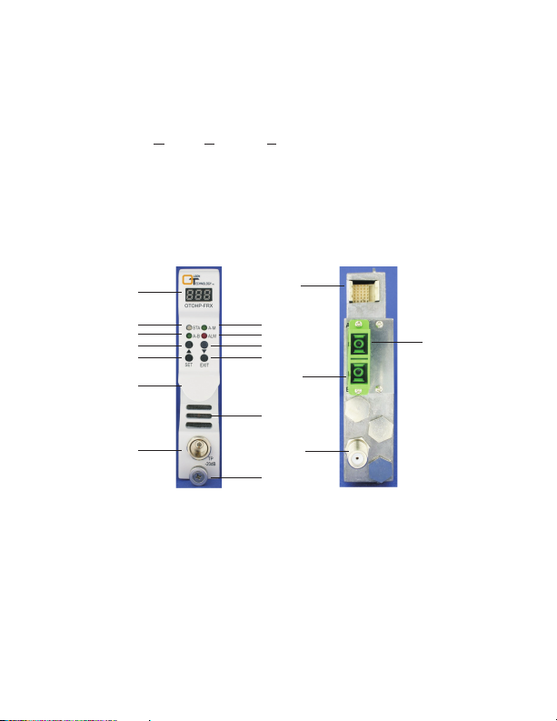
OPERATION PANEL DESCRIPTION
1
2 3
4
6
8
10
14
5
7
9
16
11
15
1. Display LED:
2. STA LED:
12
Display thestatus MGC value and alarm code of the receiver.
,
Green indicates the module is operating properly. Red indicates the
17
13
module has alarms.
3. AM-LD LED:
indicates themodule is operating under MGC
4. A-B LED: Green indicates that the unit is orking in A channel. No light indicates
Green indicates the module is operating under AGC No light
.
w
.
that the unit isworking in Bchannel.
5. ALM LED: When green, the OTOHP-FRX module is working under “ALM”
operation interface.
6. Up: Push button selects functionor parametersetting.
,
Page 4

OPERATION PANEL DESCRIPTION (CONT.)
7. Down:
.
8 Set:
9. Exit:
10 Handle: Used tohandlethemodule when being installed oruninstalled
11 Heat dissipation hole:Air flowoutofthis hole dissipates theheat.
12 TP:
13 Thumbscrew: Fixes the moduleto thechassis.
14. 30-pin Connector:
15. Optical InputPort: Port foroptical input connector type is SC APC.
16. Optical InputPort: Port foroptical input connector type is SC APC.
17. RF InputPort: Port forRF input connector type isF female.
..
1 Inspect for bent pins on the backplane connector at the rear of the module
..
2 Gently insert each module into a slot in the front of the chassis Be careful to align
3. Tighten the captive thumbscrew on the frontof the module
CAUTION: Using mismatched optical connectors will damage the connectors and
degrade system performance. Ensure that each fiber has a matching connector.
4. Repeat Steps1 through 3 to install the remainingmodules in the chassis
5. Use an optical power meter to verify that the optical input level on specification
Note: If the power supply turns on after the OTOHP-FRX forward path receiver is
inserted, the Display LED will flash for 5 seconds, and indication the receiver is selfchecking.
.
6 Verify that the correct optical connector will be attached to the optical connector on
7. Connect the optical fiberstotheappropriate OPT IN adapter onthe rearpanel.
8. Connect the RF cordtotheappropriate RF OUT connector on therearpanel.
Push button selects function orparameter setting.
Push button confirm function orparameter setting selection.
Push button exit certainoperation mode
..
.
Test point for RFoutput, -20dB F type maleconnector
.
.
connector type is male.
Straighten anybent pins before installing the module
the metal guide rails on the top and bottom of the module with the nylon guides in
the interiorof the chassis housing
value.
the module. Clean boththebulkheadand fiber connectors.
,
,
,
,
Provides power and signals to the chassis back plane
,-
INSTALLATION
.
.
.
,/
,/
.
.
,
.
Page 5
INSTALLATION (CONT.)
9. Push SET button, Set RF TP Channels as described below. Using a signal level
meter, measure the RFoutput at the RF TP test point (20dB belowactual level) on
the frontpanel and verify thatit is setat the specifiedvalue for thatchannel. Further
adjust the RF outputlevelifrequired using MGC function
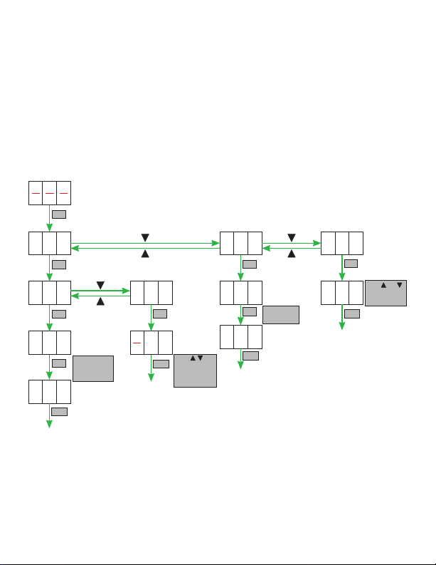
FRONT PANEL NUMERIC DISPLAY OPERATION DESCRIPTION
First pushSET on theLED display and set function.
A01: AGC/MGC setting menu
A02: Channel selection menu
SET
A03: Alarm menu
A01
SET
1
SET
OFF
SET
0N
EXIT
AGC or MGC,
“ON” is AGC,
“OFF” is MGC
SET
EXIT
0
Push , and
SET to set the
attenuation
(-20 to 0dB)
A2002
SET
A
SET
6
EXIT
Choose A or
B channel
A0003
SET
3
EXIT
Push and
to view the
alarm code.
x
Page 6
UNINSTALL THE RECEIVER MODULES
DANGER: Laser Radiation—Avoid direct exposure to beam. Inbound laser radiation
associated with this optical input jumper may be generated by a Class IIIb laser product.
Disconnected optical connectors might emit invisibleoptical radiation. Laser light, visible
or invisible, can seriously injure eyes and even cause blindness.
.()
1 Disconnect the optical fiber s from the rear panel of the receiver. Immediately
place protectivecaps over the bulkhead and fiber connector
.-.
2 Disconnect the RFcables from the F connectors
3. Loosen the thumbscrew on the front panel of the module CAUTION: Do not pull
.
.
on the thumbscrew to remove the module. Pull on the handle that the thumbscrew
goes through to removethemodule.
4. Gently pull the module from the chassis using the handle that the thumbscrew
goes through
.
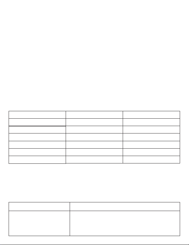
ALARM DEFINITIONS
First pushSET on theLED display and set function.
Displayed Message
000
001
002
003
004
005
Alarm Status
No alarm
Optical input low for Port 1
Optical input high for Port 1
Optical input low for Port 2
Optical input high for Port 2
Module temperature high
System Response
STA LED is green
STA LED turns to red
STA LED turns to red
STA LED turns to red
STA LED turns to red
STA LED turns to red
TROUBLESHOOTING
When Status light is red operator can use “ ” and SET push button switch to
, ▲", "▼ " "
check the alarms. DANGER/CAUTION: Do not remove the cover of the receiver or
attempt to modify any part of it under any circumstances. Removing the cover could
cause irreparable damage totheunit,and will void yourwarranty.
Problem
Steps to Take
RF input low.
1. Verify optical input powerrange is0 to -18dBm.
2. If all is normal, contact Olson Technology Inc. for
further troubleshooting.
Page 7
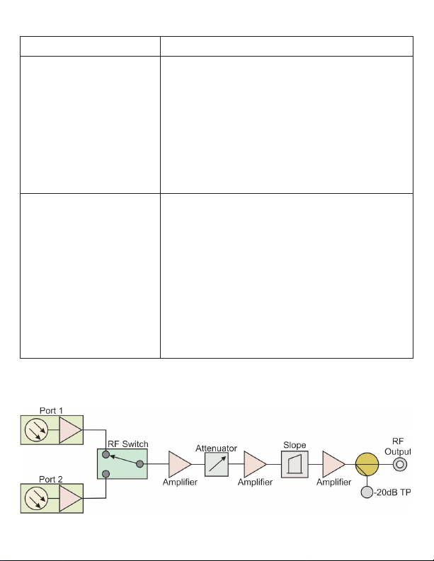
Problem
No RF power at the
RF output port.
RF output power is lower
than the required amount.
OTOHP-FRX - BLOCK DIAGRAM
TROUBLESHOOTING (CONT.)
Steps to Take
1. Clean theopticalconnector.
2. Verify the optical input power using an optical
power meter.
3. Try to adjustthe RFoutput through MGC function.
4. Measure theRFpowerat output port.
5. If there is no RF power at the output port, the unit
must be returnedto the factory for service.Contact
Olson Technology Inc.for moreinformation.
1. Ensure allconnectorsareclean.
2. Verify the cable is terminated with the correct
connector type
.
3. Verify that the optical input power is within the
normal range.
4. Try to adjustthe RFoutput through MGC function.
5. Measure theRFpowerat output port.
6. If the RF power is still low, the unit must be
returned to the factory for service. Contact Olson
Technology Inc.for moreinformation.
Page 8
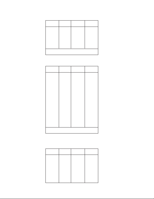
SPECIFICATIONS
Optical Characteristics (with SM 9/125µm Fiber)
Min Typ Max Units
Operating Wavelength 1260 1620 nm
Optical Input Power -3 +3 dBm
Optical Return Loss -55 dB
Optical Input Ports 2
Optical Connector SC/APC
RF Output & Performance Characteristics
Min Typ Max Units
Frequency Range 54 1,000 MHz
Band Flatness -0.75 +0.75 dB
1
RF Output Return Loss 18 dB
Output Level +35 dBmV
RF Attenuation Range 0 +20 dBm
Impedance 75 Ohms
CNR 51 dB
2
CSO 63 dB
3, 4
CTB 67 dB
3, 4
RF Test Point -20.75 -20 -19.25 dB
RF Connectors F-female
Electrical & Environmental Characteristics
Min Typ Max Units
Operating Temp. Range 0 +50 °C
Storage Temp. Range -40 +65 °C
Relative Humidity 10 90 %
P. S. Voltage +24 V
5
DC
Power Consumption 10 W
NOTES:
1) Band flatness is over a
54-1,000MHz range.
2) Received optical power of
-1dBm with 3.5% OMI per
channel, 0dB attenuation
setting.
3) +35dBmV output.
4) NTSC 77 channel loading.
5) Non-condensing.
 Loading...