

Page 1
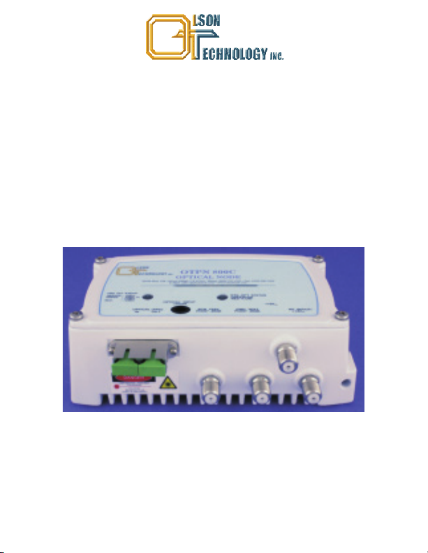
OLSON TECHNOLOGY PREMISE NODE
025-000493 Rev X6
OTPN-800CH
INDOOR OPTICAL NODE
INSTRUCTION MANUAL
Phone: (209) 586-1022
(800) 545-1022
Fax: (209) 586-1026
E-Mail: [email protected]
www.olsontech.com
10/07/10
Page 2

SAFETY WARNINGS
LASER RADIATION
The OTPN-800CH may be equipped with a laser transmitter which emits invisible
radiation that can cause permanent eye damage. AVOID DIRECT EXPOSURE TO
BEAM. Operate the transmitter only with the proper optical fiber installed in the
transmitter optical connector. Power to the OTPN-800CH should be turned-off or
preferably, disconnected whenever the optical connector cover is opened and there is
no installed fiber (as when the fiber connector is being installed or removed from the
transmitter connector).
NEVER
USE ANY OPTICAL INSTRUMENT TO VIEW THE OUTPUT OF THE
LASER TRANSMITTER. “OPTICAL INSTRUMENT” INCLUDES MAGNIFYING
GLASSES, ETC.
NEVER
LOOK INTO THE OUTPUT OF THE LASER TRANSMITTER
NEVER
LOOK INTO THE OUTPUT OF A FIBER CONNECTED TO A LASER
TRANSMITTER.
NEVER
LOOK INTO OR USE ANY OPTICAL INSTRUMENT TO VIEW THE
DISTANT END OF A FIBER THAT MAY BE CONNECTED DIRECTLY OR VIAAN
OPTICAL SPLIT, TO A TRANSMITTER THAT MAY BE OPERATING. THIS
SPECIFICALLY APPLIES TO FIBERS THAT ARE TO BE CONNECTED TO
RECEIVERS (SUCH AS THE OTPN-800CH) OR OTHER DEVICES AT ANY
DISTANCEFROM THE LASERTRANSMITTER.
HIGH VOLTAGE
The power supply section (bottom section) of the OTPN-800CH contains no user
serviceable parts. There is exposed high voltage inside this section. Only factory
service technicians shouldopen thepower supply section.
SHOCK HAZARD
The OTPN-800CH is designed forindoor useonly. Direct exposure tomoisture mustbe
avoided. Connect theAC Adapter intothe OTPN-800CH plugging the adapter
into the wall.
BEFORE
Page 3
INTRODUCTION
The OTPN-800CH is a high-quality, cost-effective, bidirectional CATV node designed
around the latest optical receiver technology. It is designed to operate and meet full
specifications with optical input levels ranging from -8dBm to +2dBm. The receive RF
path includes provisions for plug-inequalizers to provide for sloped output responseas
well as user adjustable padding to set the forward and reverse RF gains. The OTPN800CH is available with three different band splits; 1) 5-42/54-1,000MHz, 2)
5-30/45-
1,000MHz, 3) 5-65/85-1,000MHz
The OTPN-800CH can be equipped with an optional return laser transmitter. An AC
adapter is withan inputrange of 100-240V , 50/60Hz issupplied witheach unit.
AC
INSTALLATION / ENVIRONMENTAL CONSIDERATIONS
The OTPN-800CHis specifiedto operate from -10°C to+55°C. Itshould be mounted in
an adequately ventilated area. Like any otherelectronic equipment,it willprobably have
a longer life span if it is not operated at the upper limit of the temperature range.
Installation in wet areas or areas of extremely high humidity should be avoided. The
OTPN-800CH should notbe installedin areas thatare accessibleto children.
The OTPN-800CH may be installed and operated in any position on a flat surface. The
unit has two slots in the bottom plate to accommodate mounting hardware. The unit
should be mounted by sliding over one screw and then tightening the other screw. If
mounting requires a wood screw, use #6 or #8 (maximum) pan-head sheet metal
screws. If mountingwith amachine screw (totapped holes),use 6-32 pan-headscrews.
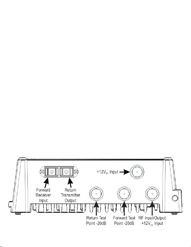
Figure 1 - OTPN-800CH Inputs and Outputs
Page 4

OPTICAL CONNECTORS AND CLEANING
The standard optical connector is available in SC/APC or FC/APC type terminations.
The left port is for the forward band receiver. The right port closest is for use with the
return band transmitter.
The fiber ends can be damaged by the insertion of contaminated connectors. Some
types of customer damage to connectors are not covered under warranty. Fiber
connectors should never be left uncovered. Prepackaged alcohol wipes are the most
convenient means of cleaning optical connectors. Clean alcohol and lint free wipes or
swabs may alsobe used.
POWERING
Apply only +12 V to either the “F” connector closest to the top cover of the unit, or
DC
through a power inserter inseries with theMain RF outputconnector, the“F” connector
closest to the outside edge of the housing. NOTE: The center conductor of the “F”
connector is “+”and theshield is ground.
OPERATIONAL SETUP - RECEIVER (FORWARD PATH)
The OTPN-800CH optical receiver as the last component in a specific optical link will
provide carrier-to-noise performance and an RF output level that is dependent on
several parameters. The RF input levelto the source optical transmitter and the optical
input level tothe OTPN-800CHbasically determine thelink performance.
The optimum RF input level to any optical transmitter is dependent on the number of
channels beingtransmitted. Asthe number of carried channels is lowered, theRF input
level to the transmitter can be raised. This results in increased RF levels at the OTPN800CH receiver. This improves the carrier-to-noise ratio over the link. Links should be
designed and transmitters should be set up using values that represent the maximum
number of channelslikely tobe carried.
The receiver output power isalso affected by the amount of equalization used.The use
of a lower value equalizer will require reducing the output level as measured at the
highest channel. Thisis becausethe attenuationof thelower channels isreduced.
Table 1 assumesapproximately 77channels from54MHz to550MHz anddigital loading
from 550MHz to 1,000MHz at-6 dB belowthe carrier.The OTPN-800CLdoes not have
a forward equalizer, and therefore has 0dB of slope (flat). This unit is designed to work
with shortcoax runs.Extended lengths of coax willcause downsloping (lower RF level)
of higher frequencies.
Page 5
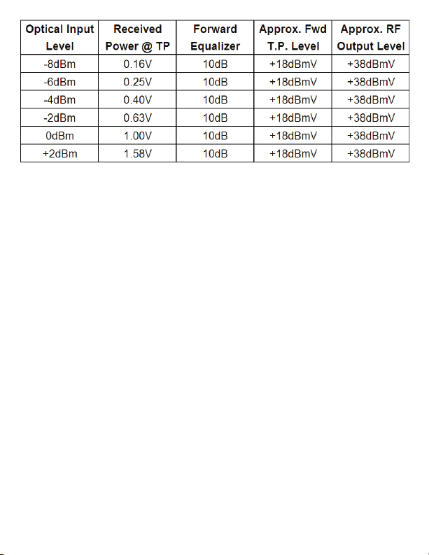
Table 1 - Setup Reference
Although the node will operate at optical input levels as high as +2dBm, there is little
improvement in the CNR performance of the node at optical input levels above 0 dBm.
For optimum distortion performance, it is recommended that the optical input to the
node be kept at or below 0 dBm. The Olson Technology Model OTOA-1000 optical
attenuator is ideal for this application. To lower the output level the adjustable pad
should be increased but a reduction below +38dBmV output at 547.25 MHz by this
method is not recommended. If lower output is desired, the unit should be set for
+35dBmV andan in-line pad added tothe RF output to reducethe output level. This will
maintain optimum CNR performance. This will also reduce the OMI of the return
transmitter if soequipped.
Unlike many optical nodes, the OTPN-800CH is designed to give full output performance at an input of -8 dBm. Figure 1 shows the approximate CNR performance at
various input levels and channel loading. This performance can vary considerably
depending upon fiberand laserperformance so itis presentedas a designaid only.
The OTPN-800CH ships with an10dB forward equalizerwhich gives 6dB of slope from
54-1,000 MHz. This can be changed by the user to vary theamount ofslope thatthe unit
has.A higher value equalizer will give moreslope, whilea lowervalue equalizerwill give
less slope. This is so that the unit can be properly setup for the amount of coax that the
output will be going through. Longer distances require more slope then shorter
distances.
Page 6
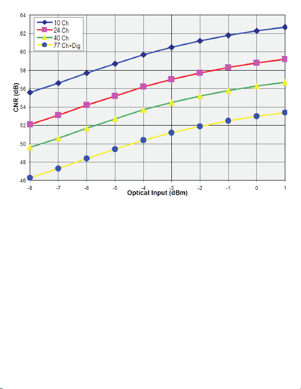
Figure2-Typical CNR vs. Optical Input Level
INTERNAL TEST POINTS and ADJUSTMENTS
The OTPN-800CH receiver has an internal adjustable pad to allow the RF output level
of the node to be adjusted. There is also a plug-in equalizer to compensate for cable
slope. These adjustments are accessed by removing the 8 thumbscrews that hold the
top cover on. The unit should not be operated for extended periods with the top cover
removed. This is because of RF ingress and contamination from dirt or other objects.
When replacing the top cover, be sure to firmly tighten all thumbscrews. RF ingress or
oscillation can becaused byloose screws.
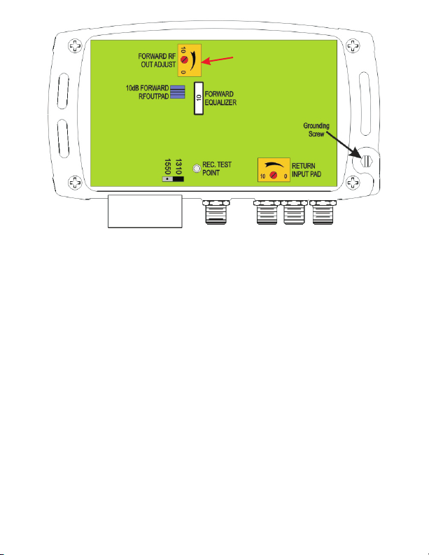
Figure 3 shows the locations of the internal adjustments. There are two forward RF out
adjustments, a variable attenuator, and a 10 dB switchable pad. This gives the unit 20
dB ofRF output range. If theoptical input is between -3dBmand +2dBm, then the 10dB
switchable pad should be as shown above with the flat part being parallel to the front of
the unit by rotating thejumper ifneeded. The variable attenuator can thenbe usedto get
the RF output to the correct level. If the optical input is in between -8dBm and -3dBm,
then position the 10dB switchable pad shouldbe rotatedso thatit isperpendicular tothe
front of theunit. And thenadjust the variable attenuatorfor properRF output.
Page 7
Note: This yellow housing
Note: This yellow housing
may be removed on
may
be removed on
some units.
units.
some
Figure 3 - OTPN-800CH Location of Internal Adjustments
Return Transmitter Setup
The specification for the return band transmitter RF input level is -57dBmV/Hz
(measured at RF Out Port). This value operated the system at the NPR threshold. The
unit has an adjustable attenuator in the return path.A -20dB testpoint is included in the
return path. The single carrier equivalent of -57dBmV/Hz is +9dBmV per carrier. The
return pad mustbe adjustedto set thecarrier to+9 dBmV afterthe attenuator. With atest
carrier present at the port (+19dBmV max), measure the level at the return -20dB test
point.Adjust the pad fora -20dBtest point readingof -11dBmVreturn input.
External Test Points
The OTPN-800CH has three external test points. The received “Optical Power” T.P. is
calibrated at 1V per mW @ 1310 nm. Measure with a high impedance voltmeter. This
test point is for monitoring purposes as well as initial setup. Measure the optical power
with a at the time of installation. The reading at 1550nm may be off by 15% even
assuming that the internal jumper has been changed. The jumper is located inside the
unit near the receive level T.P. as shown above. The position closest to the test point is
for 1310nm, andthe positionfarther from thetest pointis for 1550nm.
The Forward T.P. is -20dB from the receiver RF output. If the RF out is +38 dBmV, then
the T.P.will be about +18dBmV. The Return T.P.is -20dBfrom the Return transmitter RF
input. Optimal inputis +9dBmV(57dBmV/Hz), so theT.P. should read-11dBmV.
Page 8
System Setup & Troubleshooting
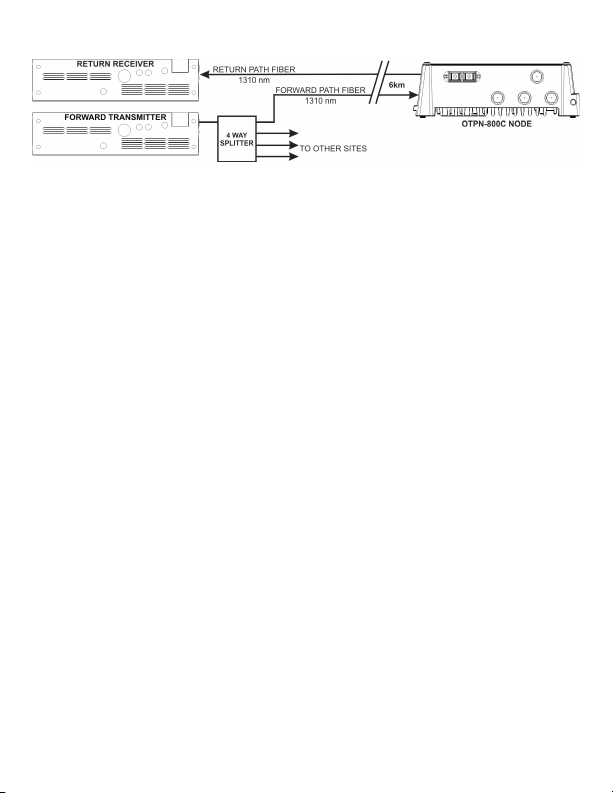
Fiber Loss at 1310nm is 0.330dB/km, and 1550 is 0.188dB/km. Using these values, if
the fiber run is 6km (3.73 miles), then a 2dBm transmitter is required for the distance. If
the forward band is being split, then the additional loss must be accounted for. A fiber
splitter generally splits the signal equally between each output. If the forward path is to
be split 4 ways, then a +8dBm transmitter is required to cover the 6 km. If the links
coming outof thesplitter are different lengths, then be sure to have enoughtransmitting
power to reach the receiver with the longest link. Those with shorter links can be
attenuated to lower the signalto alevel thereceiver can use. To be sure thereceiver isin
the correctrange, measure the Receive T.P. usinga DVM. The best operatingrange for
most OT forward receivers is 0.5V to0.9V (approximately -3dBm to -0.5dBm). Some
DC DC
have operating rangesdown to-8dBm.
If the fiber run is less than a few km, then the optical signal must be lowered before the
system can operate correctly. Failure to do so may cause an overloaded or distorted
picture. The easiest wayto lowerthe signalis to use an optical attenuator.OT makesan
easy to use attenuator calledthe OTOA-1000.This provides for aneasy wayof lowering
the optical signal by wrapping the fiber tightly into the slot inside of it. Every fiber is
different, some may require more wraps then others. Generally one wrap around the
largest of the three post will lower the optical signal by approximated 1.75dB. The two
smaller post attenuate the signal more. If the received power is too low, but the correct
power transmitter isbeing used,please consult thefollowing:
1: Be sureall fiberconnectors are cleanusing anapproved fiber cleaner.
2: Be sure the fiber connectors are all of the same type. All OT units ship with either
SC/APC or FC/APC style connectors. These will be green in color. You can NOT mix
green andblue connectors, as the endterminations are different. This can also resultin
low signal orsnowy picture.
3: Broadband RF transmitters such as those made by OT require the use of SM fiber.
MM will notwork. Attempting touse MMfiber willresult inlow signal orsnowy picture.
 Loading...