

Page 1

OTR-3550-DC
FREQUENCY AGILE - TELEVISION PROCESSOR
FOR
CHINA PAL D STANDARD
INSTRUCTION MANUAL
Phone:
E-Mail: [email protected]
025-000187 REV B 11-20-02
(209) 586-1022
(800) 545-1022
Fax:
(209) 586-1026
www.olsontech.com
Page 2
1) INTRODUCTION
The Olson T echnology OTR-3550-DC is a frequency agile television processor which consists of an agile
demodulator internally connected to an agile modulator . This unit will select any broadcast VHF/UHF or cable
input channel from 49.75 MHz to 855.25 MHz, and will provide a high level (+60dBmV typical) output on any
channel from 49.75 MHz (channel DS-1) through 543.25 MHz (channel SD-22). All input and output channels are selectable in .25 MHz increments by front panel DIP switches.
The OTR-3550-DC uses dual SA W filtering for 60dB adjacent channel rejection and has high level spurious
free output. This unit also offers the unique Olson Technology feature of >80dB out-of-band carrier to noise
ratio, which will allow virtually unlimited numbers of the OTR-3550-DC to be combined without the need for
external band pass filters.
The OTR-3550-DC has low power consumption (17 watts @ 220 VAC) for economical and reliable long
term operation.
OTR-3550-DC
FREQUENCY AGILE - F .C.C. COMP ATIBLE
TELEVISION PROCESSOR
2) INPUT CHANNEL SELECTION - DEMODULA TOR
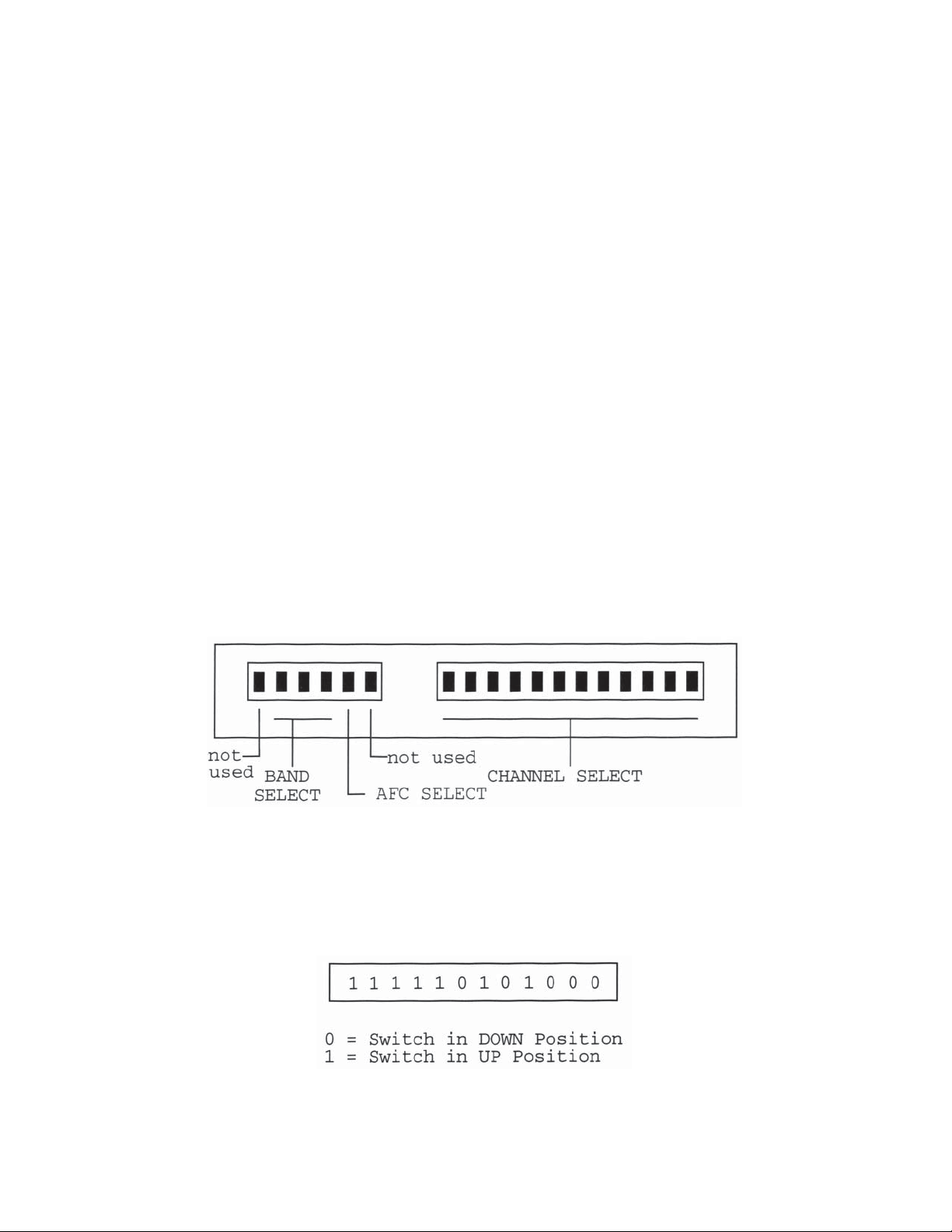
Remove the front panel plate marked “Input Channel Select” to expose the channel select and band select
DIP switches as shown in Figure 1.
FIGURE 1 - INPUT CHANNEL SELECT DIP SWITCHES
A) CHANNEL SELECTION - Channel selection is accomplished by properly setting the 12-position
DIP switch to the correct code for the desired channel. Switch codes can be selected from T able 4 at
the rear of this manual. Set the DIP switches from left to right as shown in the table. For example, if
channel DS-1 is selected, its corresponding switch code is:
CAUTION: The switch codes for input and output channel selection are completely different. Be sure to refer to
the correct table and set the switches carefully .
025-000187 REV B
Page 2
Page 3

B) BAND SELECTION - Band selection is accomplished by setting the 6-position DIP switch to select
the correct band for the desired channel. The second, third and fourth switch positions of the 6position DIP switch are used for band selection. Switch settings for the band select switch are included
with the channel codes in T able 4 at the rear of this manual.
For example, the correct band switch setting for channel DS-1 is:
C) AFC SELECTION - The OTR-3550-DC has an AFC circuit which may be switched-on if
the channel being received has a tendency to drift around in frequency . Although this feature may not
normally be needed, it may be activated by moving position 5 of the 6-position DIP switch down.
The AFC is shown as selected of f in T able 4.
For example, the correct setting for channel SD-22 with the AFC on would be:
D) INPUT CONNECTION - After the input selection DIP switches have been properly set (Steps A
through C), connect an antenna or cable source to the RF Input fitting. Any VHF, UHF or cable
source can be connected to the RF input. For optimum video quality , the input signal level should be
+10dBmV . This unit has an internal squelch circuit that will cut off signals below -30dBmV .
3) DEMODULA TOR AGC ADJUSTMENT
The demodulator delayed AGC adjustment is factory set for a +5 to +10dBmV threshold. This setting provides
the best signal-to-noise ratio for low level off-air signals.
When operating the OTR-3550-DC with cable channels at the input, where high-level adjacent channel signals
may be present, adjacent channel performance may be improved by lowering the AGC threshold level.
T o adjust the delayed AGC threshold level for cable signal inputs:
A. Connect a cable source carrying three adjacent channels at a level of +20dBmV maximum to
the RF input connector. Connect a television receiver , through approximately 50dB of attenuation
so as not to overload it, to the OTR-3550-DC output.
B. Set the input channel select DIP switches to the channel located in the center of the three
channels. Set the television receiver to the output channel of the OTR-3550-DC.
025-000187 REV B
C. Remove the OTR-3550-DC top cover and locate the delayed AGC control potentiometer
R54. R54 is located near the center of the circuit board towards the front of the unit. Adjust
the demodulator delayed AGC control (R54) slightly for the least amount of adjacent channel
interference as seen on the television receiver .
Page 3
Page 4
4) OUTPUT CHANNEL SELECTION - MODULATOR SECTION
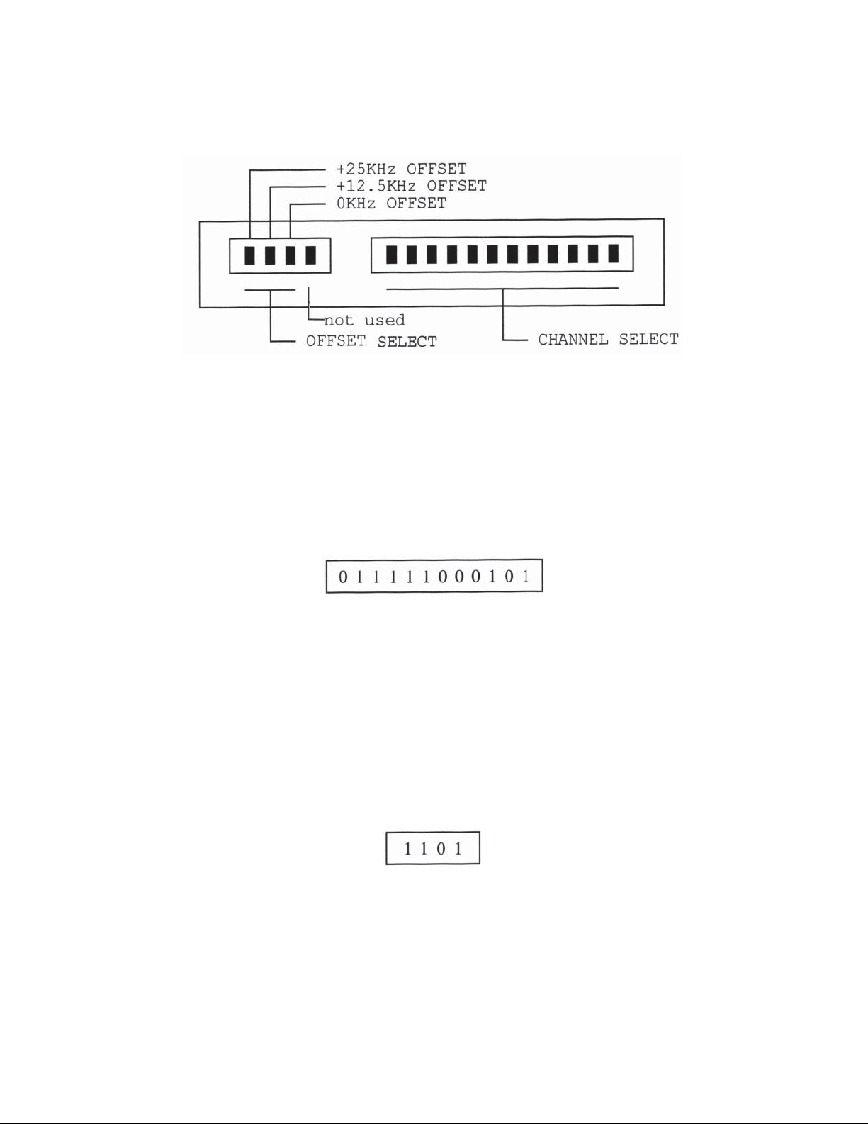
Remove the front panel plate marked “Output Channel Select” to expose the channel select and offset select DIP
switches as shown in Figure #2.
Figure #2 - OUTPUT CHANNEL SELECT DIP SWITCHES
The OTR-3550-DC has a rear-panel toggle switch which is also used in setting output frequency .
A) CHANNEL SELECTION - Channel selection is accomplished by properly setting the 12-position
DIP switch to the correct code. Switch codes can be selected from T able 5 at the rear of this
manual. Set the DIP switches from left to right as shown in the table. For example, if channel DS-1
is selected, its corresponding switch code is:
B) OFFSET SELECTION - Although it may not be required in P AL D China applications, the
OTR-3550-DC has a feature which allows output channels to be offset from their nominal frequency .
Fixed offsets of +12.5 KHz and +25 KHz are available in addition to operation on the nominal channel
frequency (+0 KHz offset).
If offset output frequencies are desired, the 4 position DIP switch must be set properly . The +0 KHz,
+12.5 KHz, or +25 KHz position of the 4-position switch must be moved to the down position - all
other positions must be in the up position. These positions are identified in Figure 2.
For example, if 0 KHz offset (normal operation) is desired, the proper switch settings would be:
The fourth position of this switch is not used. Settings for this switch are not shown in T able 5.
C) OUTPUT CONNECTION - The output signal is present at the RF output connector . This unit has an
output test point which is useful when recording operating levels, trouble-shooting, etc. The RF test
output is approximately 20 dB below the main output. Reference readings may be taken at the RF test
output after the output level is properly set for the system.
025-000187 REV B
Page 4
Page 5
5) RF AND AURAL CARRIER LEVEL ADJUSTMENT
A) Connect a spectrum analyzer or field strength meter to the RF output connector. Set the video carrier
to the desired level with the RF output level control.
This unit is capable of +60dBmV typical output and can be adjusted downward by at least 10dB. For
best performance, do not reduce the output to less than +53 dBmV . If lower output levels are required,
install a fixed attenuator pad at the rear of the unit and set the unit so it’s actual output level is above
+53 dBmV. If possible, operate the output at +55 to to +57dBmV but check that there is still some
output level reserve.
B) Tune the field strength meter to the aural carrier (6.5MHz above the video carrier). Using the Aural
Carrier control, adjust the aural carrier level to be approximately 15dB below the video carrier.
CAUTION: Reducing the visual/aural carrier ratio to less than 15 dB can result in high out-of-band spurious
signals in adjacent channels.
6) SELECTION OF NON-ST ANDARD INPUT AND OUTPUT FREQUENCIES
The OTR-3550-DC can select any input frequency in .25 MHz increments from 49.75 MHz to 855.25 MHz.
Also, it can select in .25 MHz increments, any output channel from 49.75 MHz to 543.25 MHz.
DIP switch settings for channels or frequencies not listed in Tables 4 & 5 can be computed using the information
below . The procedure for computing DIP switch settings for input and output channels is the same, except that
some of the numerical values are different.
If it becomes necessary to use the procedure below to compute a non-standard value, it may be helpful to
work out the settings for a channel that IS in the table so you can compare your results with those which are
known to be correct. If you arrive at the same settings for a ST ANDARD channel, as listed in the rear of this
manual, then it would be OK to proceed to work out the settings you need for a non-standard channel.
TO COMPUTE THE CORRECT SETTINGS FOR INPUT FREQUENCIES:
A) Determine the video carrier frequency of the desired channel (which must end in .00, .25, .50, or .75).
B) Compute the number “N” needed to work out switch codes:
Use the formula, N = (38 + Fc)4 Where Fc = channel video carrier frequency .
Set the DIP switches to = “N” as a binary number:
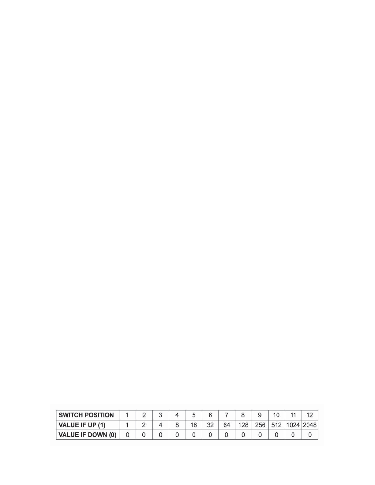
Each switch position has an equivalent value as indicated in T able 1. A switch position is either UP = OFF =
(VALUE) or is DOWN = ON = (0).
025-000187 REV B
T able #1. INPUT CHANNEL SELECT DIP SWITCH VALUES
Page 5
Page 6
Using the values shown in T able 1, move DIP switch positions UP until the total of the UP positions
equals the number “N”.
The easiest way to do this is to work out the settings on paper.
Subtract from “N” the largest position value possible (and note the position as a “1”), then repeat this
using the remaining value(s) of “N” until the remainder is exactly zero. Note switch positions used to
add to the total value as “1” and the positions NOT used as “0”.
C) Use your paper notes of which positions are “1” and which are “0” to set the DIP switch positions for
the desired frequency .
D) Set the 6-position band selection DIP switch for the proper frequency range using T able 2 below .
BAND SELECT
DIP SWITCH FREQUENCY RANGE
1 0 1 1 1 1 - 48 MHz to 168 MHz
1 1 0 1 1 1 - 169 MHz to 447 MHz
1 1 1 0 1 1 - 448 MHz to 855 MHz
T able #2 BAND SELECTION DIP SWITCH VALUES
TO COMPUTE THE CORRECT SETTINGS FOR OUTPUT FREQUENCIES:
A) Determine the video carrier frequency of the desired channel (which must end in .00, .25, .50, or .75).
B) Compute the number “N” needed to work out switch codes:
Use the formula, N = (605.75 + Fc)4 Where Fc = channel video carrier frequency .
Set the DIP switches and the rear panel toggle switch to = “N” as a binary number:
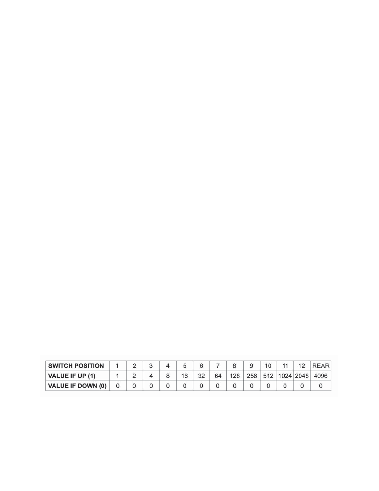
Each switch position has an equivalent value as indicated in T able 3. A switch position is either UP =
OFF = (VALUE) or is DOWN = ON = (0).
025-000187 REV B
T able # 3. OUTPUT CHANNEL SELECT DIP SWITCH V ALUES
Page 6
Page 7

Using the values shown in T able 3, move DIP switch positions and the rear panel toggle UP until the total of the UP
positions equals the number “N”.
The easiest way to do this is to work out the settings on paper.
Subtract from “N” the largest position value possible (and note the position as a “1”), then repeat this
using the remaining value of “N” until the remainder is exactly zero. Note switch positions used to add
to the total value as “1” and the positions NOT used as “0”.
C) Use your paper notes of which positions are “1” and which are “0” to set the switch positions for the
desired frequency .
7) MISCELLANEOUS
A) When installing this unit in an equipment rack it is best to leave an empty rack space above and below
this unit to allow for optimum air circulation.
B) The OTR-3550-DC is equipped with a 0.25 amp slo-blo fuse. For continued safety and to maintain
proper performance of this unit, replace only with equivalent fuse.
025-000187 REV B
Page 7
Page 8

T ABLE 4
OTR-3550-DC
ST ANDARD P AL CHINA
INPUT DIP SWITCH SETTINGS
1 = UP 0 = DOWN
VIDEO
CH. FREQUENCY DIP SWITCH SETTINGS
DS-1 49.750 101111 1111 1010 1000
DS-2 57.750 101111 1111 1110 1000
DS-3 65.750 101111 1111 1001 1000
DS-4 77.250 101111 1011 0011 1000
DS-5 85.250 101111 1011 0111 1000
Z-1 112.250 101111 1001 1010 0100
Z-2 120.250 101111 1001 1110 0100
Z-3 128.250 101111 1001 1001 0100
Z-4 136.250 101111 1001 1101 0100
Z-5 144.250 101111 1001 1011 0100
Z-6 152.250 101111 1001 1111 0100
Z-7 160.250 101111 1001 1000 1100
DS-6 168.250 101111 1001 1100 1100
DS-7 176.250 110111 1001 1010 1100
DS-8 184.250 110111 1001 1110 1100
DS-9 192.250 110111 1001 1001 1100
DS-10 200.250 110111 1001 1101 1100
DS-11 208.250 110111 1001 1011 1100
DS-12 216.250 110111 1001 1111 1100
Z-8 224.250 110111 1001 1000 0010
Z-9 232.250 110111 1001 1100 0010
Z-10 240.250 110111 1001 1010 0010
Z-11 248.250 110111 1001 1110 0010
Z-12 256.250 110111 1001 1001 0010
Z-13 264.250 110111 1001 1101 0010
Z-14 272.250 110111 1001 1011 0010
Z-15 280.250 110111 1001 1111 0010
Z-16 288.250 110111 1001 1000 1010
Z-17 296.250 110111 1001 1100 1010
Z-18 304.250 110111 1001 1010 1010
Z-19 312.250 110111 1001 1110 1010
Z-20 320.250 110111 1001 1001 1010
Z-21 328.250 110111 1001 1101 1010
Z-22 336.250 110111 1001 1011 1010
Z-23 344.250 110111 1001 1111 1010
Z-24 352.250 110111 1001 1000 0110
Z-25 360.250 110111 1001 1100 0110
Z-26 368.250 110111 1001 1010 0110
Z-27 376.250 110111 1001 1110 0110
Z-28 384.250 110111 1001 1001 0110
VIDEO
CH. FREQUENCY DIP SWITCH SETTINGS
Z-29 392.250 110111 1001 1101 0110
Z-30 400.250 110111 1001 1011 0110
Z-31 408.250 110111 1001 1111 0110
Z-32 416.250 110111 1001 1000 1110
Z-33 424.250 110111 1001 1100 1110
Z-34 432.250 110111 1001 1010 1110
Z-35 440.250 110111 1001 1110 1110
Z-36 448.250 110111 1001 1001 1110
Z-37 456.250 111011 1001 1101 1110
SD-13 471.250 111011 1010 1111 1110
SD-14 479.250 111011 1010 1000 0001
SD-15 487.250 111011 1010 1100 0001
SD-16 495.250 111011 1010 1010 0001
SD-17 503.250 111011 1010 1110 0001
SD-18 511.250 111011 1010 1001 0001
SD-19 519.250 111011 1010 1101 0001
SD-20 527.250 111011 1010 1011 0001
SD-21 535.250 111011 1010 1111 0001
SD-22 543.250 111011 1010 1000 1001
SD-23 551.250 111011 1010 1100 1001
SD-24 559.250 111011 1010 1010 1001
DS-25 607.250 111011 1010 1000 0101
DS-26 615.250 111011 1010 1100 0101
DS-27 623.250 111011 1010 1010 0101
DS-28 631.250 111011 1010 1110 0101
DS-29 639.250 111011 1010 1001 0101
DS-30 647.250 111011 1010 1101 0101
DS-31 655.250 111011 1010 1011 0101
DS-32 663.250 111011 1010 1111 0101
DS-33 671.250 111011 1010 1000 1101
DS-34 679.250 111011 1010 1100 1101
DS-35 687.250 111011 1010 1010 1101
DS-36 695.250 111011 1010 1110 1101
DS-37 703.250 111011 1010 1001 1101
DS-38 711.250 111011 1010 1101 1101
DS-39 719.250 111011 1010 1011 1101
DS-40 727.250 111011 1010 1111 1101
DS-41 735.250 111011 1010 1000 0011
DS-42 743.250 111011 1010 1100 0011
025-000187 REV B
Page 8
Page 9

T ABLE 4 CONTINUED
OTR-3550-DC
ST ANDARD P AL CHINA
INPUT DIP SWITCH SETTINGS
1 = UP 0 = DOWN
VIDEO
CH. FREQUENCY DIP SWITCH SETTINGS
DS-43 751.250 111011 1010 1010 0011
DS-44 759.250 111011 1010 1110 0011
DS-45 767.250 111011 1010 1001 0011
DS-46 775.250 111011 1010 1101 0011
DS-47 783.250 111011 1010 1011 0011
DS-48 791.250 111011 1010 1111 0011
DS-49 799.250 111011 1010 1000 1011
DS-50 807.250 111011 1010 1100 1011
DS-51 815.250 111011 1010 1010 1011
DS-52 823.250 111011 1010 1110 1011
DS-53 831.250 111011 1010 1001 1011
DS-54 839.250 111011 1010 1101 1011
DS-55 847.250 111011 1010 1011 1011
DS-56 855.250 111011 1010 1111 1011
025-000187 REV B
Page 9
Page 10

T ABLE 5
OTR-3550-DC
ST ANDARD P AL CHINA
OUTPUT DIP SWITCH SETTINGS
1 = UP 0 = DOWN
REAR P ANEL TOGGLE: 1 = "HIGH" 0 = "LOW"
VIDEO REAR P ANEL
CHANNEL FREQUENCY DIP SWITCH SETTINGS TOGGLE
DS-1 49.750 0111 1100 0101 0
DS-2 57.750 0111 1010 0101 0
DS-3 65.750 0111 1110 0101 0
DS-4 77.250 0011 0101 0101 0
DS-5 85.250 0011 0011 0101 0
Z-1 112.250 0001 1100 1101 0
Z-2 120.250 0001 1010 1101 0
Z-3 128.250 0001 1110 1101 0
Z-4 136.250 0001 1001 1101 0
Z-5 144.250 0001 1101 1101 0
Z-6 152.250 0001 1011 1101 0
Z-7 160.250 0001 1111 1101 0
DS-6 168.250 0001 1000 0011 0
DS-7 176.250 0001 1100 0011 0
DS-8 184.250 0001 1010 0011 0
DS-9 192.250 0001 1110 0011 0
DS-10 200.250 0001 1001 0011 0
DS-11 208.250 0001 1101 0011 0
DS-12 216.250 0001 1011 0011 0
Z-8 224.250 0001 1111 0011 0
Z-9 232.250 0001 1000 1011 0
Z-10 240.250 0001 1100 1011 0
Z-11 248.250 0001 1010 1011 0
Z-12 256.250 0001 1110 1011 0
Z-13 264.250 0001 1001 1011 0
Z-14 272.250 0001 1101 1011 0
Z-15 280.250 0001 1011 1011 0
Z-16 288.250 0001 1111 1011 0
Z-17 296.250 0001 1000 0111 0
Z-18 304.250 0001 1100 0111 0
Z-19 312.250 0001 1010 0111 0
Z-20 320.250 0001 1110 0111 0
Z-21 328.250 0001 1001 0111 0
Z-22 336.250 0001 1101 0111 0
Z-23 344.250 0001 1011 0111 0
025-000187 REV B
Page 10
Page 11

T ABLE 5 CONTINUED
OTR-3550-DC
ST ANDARD P AL CHINA
OUTPUT DIP SWITCH SETTINGS
1 = UP 0 = DOWN
REAR P ANEL TOGGLE: 1 = "HIGH" 0 = "LOW"
VIDEO REAR P ANEL
CHANNEL FREQUENCY DIP SWITCH SETTINGS TOGGLE
Z-24 352.250 0001 1111 0111 0
Z-25 360.250 0001 1000 1111 0
Z-26 368.250 0001 1100 1111 0
Z-27 376.250 0001 1010 1111 0
Z-28 384.250 0001 1110 1111 0
Z-29 392.250 0001 1001 1111 0
Z-30 400.250 0001 1101 1111 0
Z-31 408.250 0001 1011 1111 0
Z-32 416.250 0001 1111 1111 0
Z-33 424.250 0001 1000 0000 1
Z-34 432.250 0001 1100 0000 1
Z-35 440.250 0001 1010 0000 1
Z-36 448.250 0001 1110 0000 1
Z-37 456.250 0001 1001 0000 1
SD-13 471.250 0010 1011 0000 1
SD-14 479.250 0010 1111 0000 1
SD-15 487.250 0010 1000 1000 1
SD-16 495.250 0010 1100 1000 1
SD-17 503.250 0010 1010 1000 1
SD-18 511.250 0010 1110 1000 1
SD-19 519.250 0010 1001 1000 1
SD-20 527.250 0010 1101 1000 1
SD-21 535.250 0010 1011 1000 1
SD-22 543.250 0010 1111 1000 1
025-000187 REV B
Page 11
 Loading...