

Page 1

LCM-500-550
TELEVISION MODULATOR
INSTRUCTION MANUAL
Phone:
E-Mail: [email protected]
025-000181 REV C 6/20/01
(209) 586-1022
(800) 545-1022
Fax:
(209) 586-1026
www.olsontech.com
Page 2
1) INTRODUCTION
The Olson T echnology LCM-500-550 is a frequency agile F .C.C.compatible television modulator. This unit
will provide >+55dBmV output on any channel from 55.25MHz to 547.25MHz (VHF channels 2 through 13
and cable channels A through PPP). All channels are selectable by front panel DIP switches and a front panel
adjustment allows setting to F .C.C. offset frequencies.
The LCM-500-550 offers the unique Olson T echnology feature of >75dB out-of-band carrier to noise ratio.
Also, this unit uses SA W filtering for adjacent channel operation, and it provides 60dB of spurious free dynamic range. These features allow virtually unlimited numbers of LCM-500-550’ s to be combined without the
need for external bandpass filters.
The LCM-500-550 has low power consumption (14 watts @ 115 VAC) for reliable long term operation.
2) CHANNEL SELECTION
LCM-500-550
FREQUENCY AGILE - F .C.C. COMP ATIBLE
TELEVISION MODULA TOR
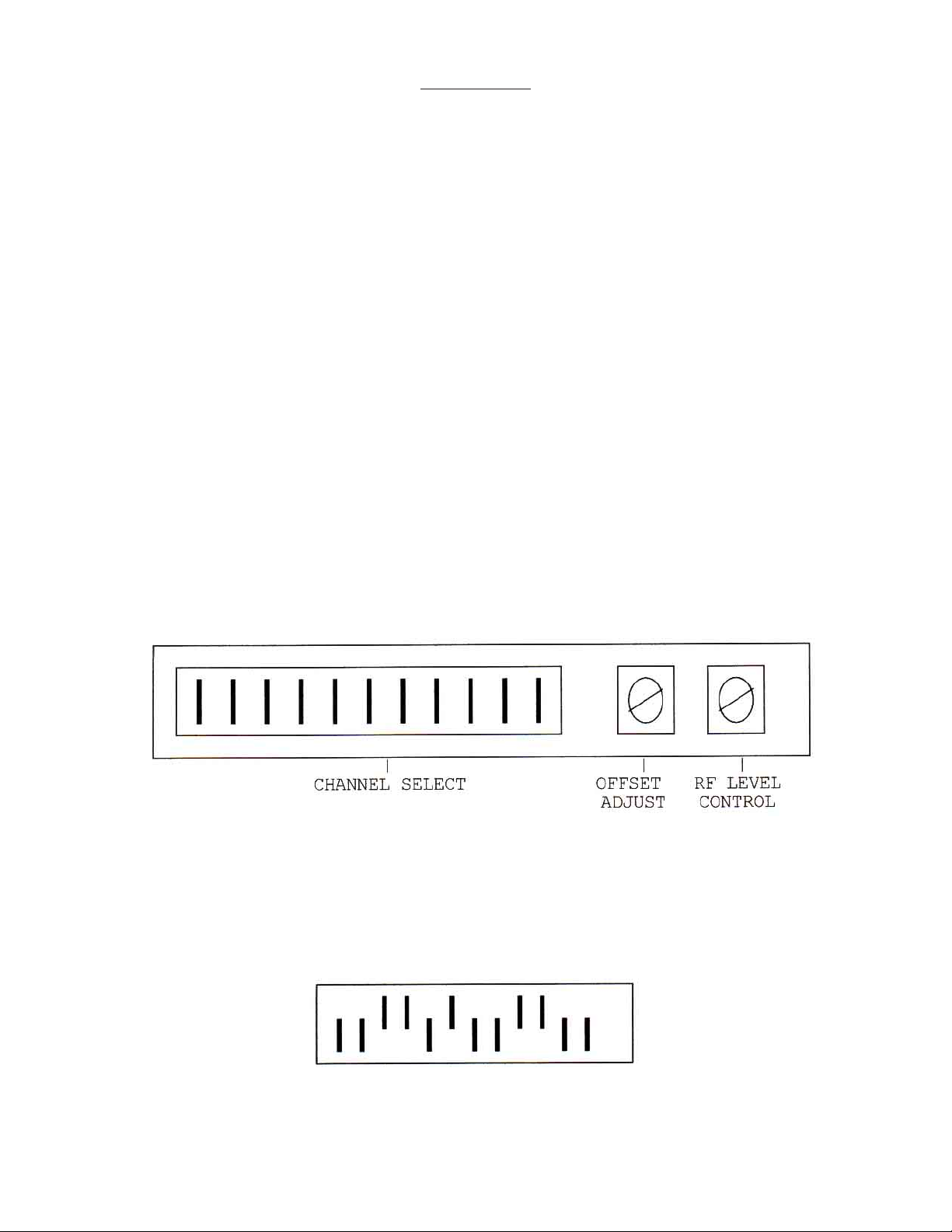
Remove the small cover plate from the front panel to expose the channel select switches and the F .C.C.
offset adjust control as shown in Figure #1. Note that the RF Level control is accessible through the level
adjustment hole in the cover plate.
FIGURE 1 - CHANNEL SELECT/OFFSET ADJUST
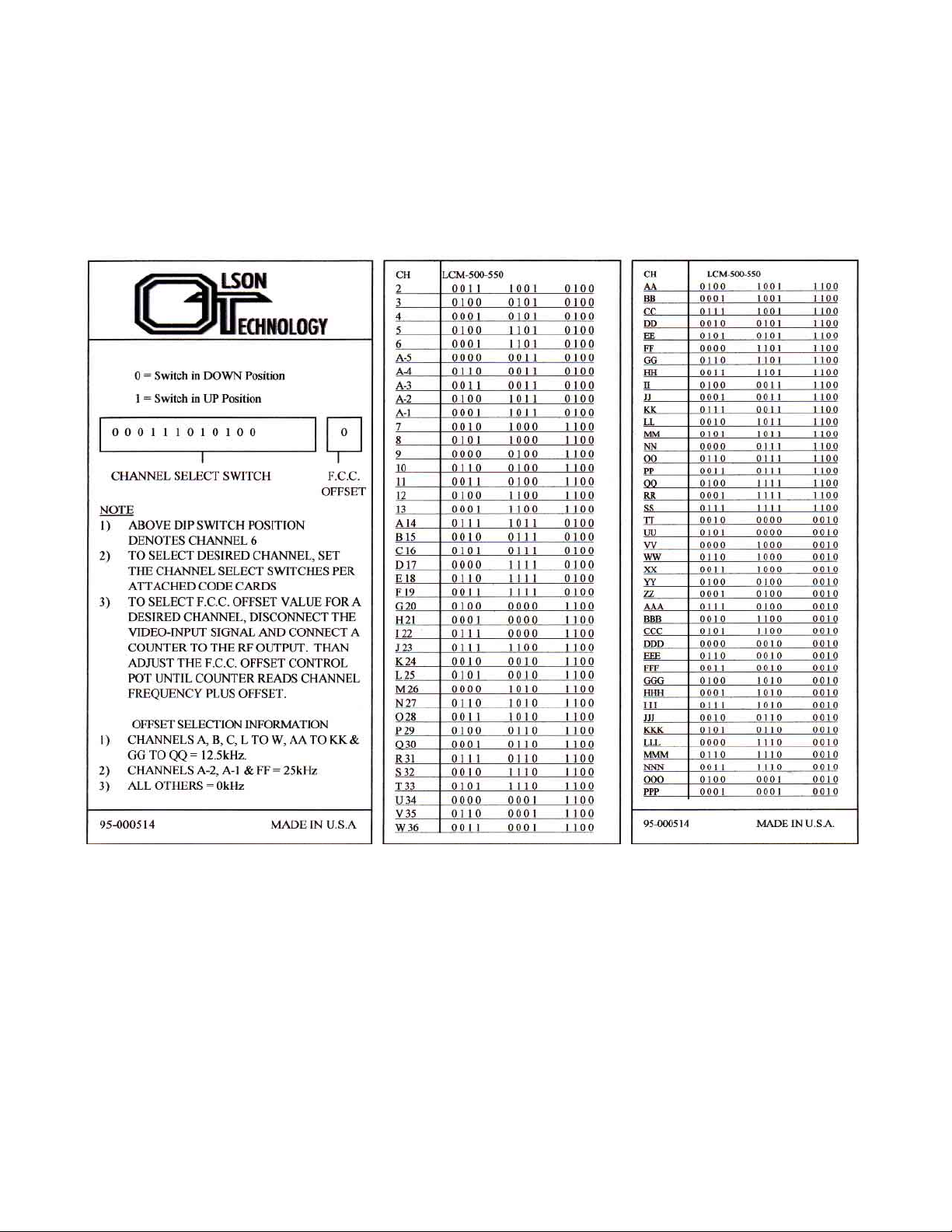
Channel selection is made by properly setting the 12-position DIP switches to the corresponding channel
code. Channel codes are shown in Figure #2 and on the code card attached to the cover plate.Set the DIP
switches from left to right. For example, if channel 11 is desired, its corresponding channel code is:
025-000181 REV C
Page 2
Page 3
3) F .C.C. OFFSET ADJUSTMENT
F .C.C. offset frequencies are shown in T able 1 and summarized on the card attached to the cover plate. T o
adjust the frequency of a selected channel to provide the correct F .C.C. offset, look up its offset frequency
in T able 1 (or use the summary attached to the cover plate). Remove the video input and connect a counter
to the RF output of the LCM-500- 550. Use the offset adjust control (marked OA) behind the cover plate
to set the output frequency to the correct value.
025-000181 REV C
FIGURE 2 - CHANNEL SELECT CODES
Page 3
Page 4
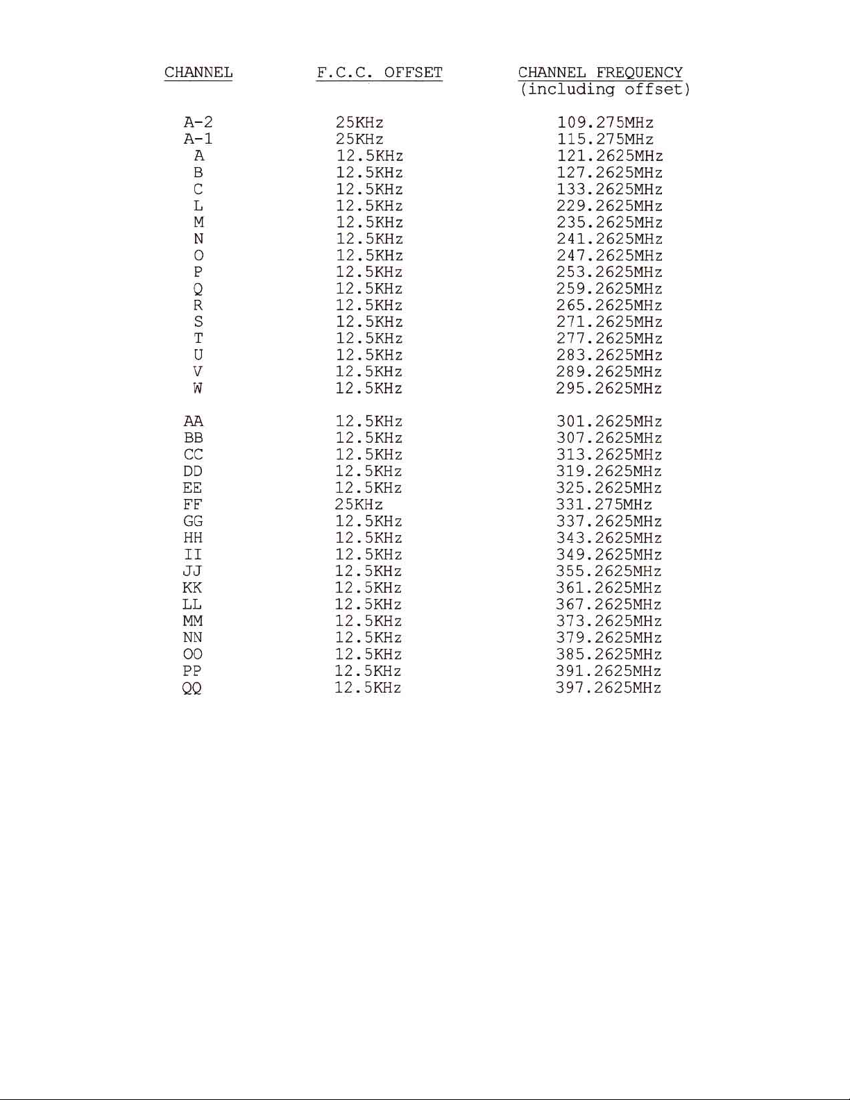
T able 1. F .C.C. OFFSET FREQUENCIES
4) VIDEO MODULA TION ADJUSTMENT
A) Connect a video source of approximately 1v p-p to the video input connector (75Ω input Z) on the
rear panel. The video should be of a reasonably bright scene (commercials are usually excellent).
B) Rotate the video modulation control (MOD) slowly clockwise until the video overmodulation light
(O/M) just turns on. The light may blink with differences in average picture level. CAUTION: If the
modulation is set too high, compression or lack of contrast will occur during high intensity scenes.
025-000181 REV C
Page 4
Page 5

5) AUDIO MODULA TION ADJUSTMENT
A) Connect an audio source of 300mv p-p (minimum) to the input connector (10K ohms input Z) on the
rear panel.
B) Rotate the audio modulation (MOD) control slowly clockwise until the audio overmodulation light (O/
M) just begins to blink. CAUTION: Overmodulation can result in severe distortion in some TV sets.
Set this control at peak program levels.
6) RF OUTPUT AND AURAL CARRIER LEVEL ADJUSTMENT
A) Using a field strength meter or spectrum analyzer, set the video carrier to the desired level with the RF
output “level” adjust pot (typically +55dBmV).
B) Tune the field strength meter to the aural carrier , which is located 4.5MHz above the video carrier.
C) Adjust the aural carrier level control (A/V) to the desired level, typically 15dB below the video carrier.
CAUTION: Reducing the visual/aural carrier ratio to less than 15dB can result in high out-of-band
spurious signals in adjacent channels.
7) MISCELLANEOUS
A) The LCM-500-550 is BTSC stereo compatible. It is shipped in the “mono” mode. T o defeat the pre-
emphasis, in order to use a composite baseband BTSC input signal, move the internal jumper plug
from W -6 “PRE” to W -6 “BY”. This plug is located on the right side of P .C. board.
B) When installing this unit in an equipment rack, it is best to leave an empty rack space above and below
this unit to allow for optimum air circulation.
C) The LCM-500-550 is equipped with a 0.5A slo-blo fuse. For continued safety , and to maintain
proper performance of the unit, please replace only with an equivalent fuse.
025-000181 REV C
Page 5
 Loading...