

Page 1
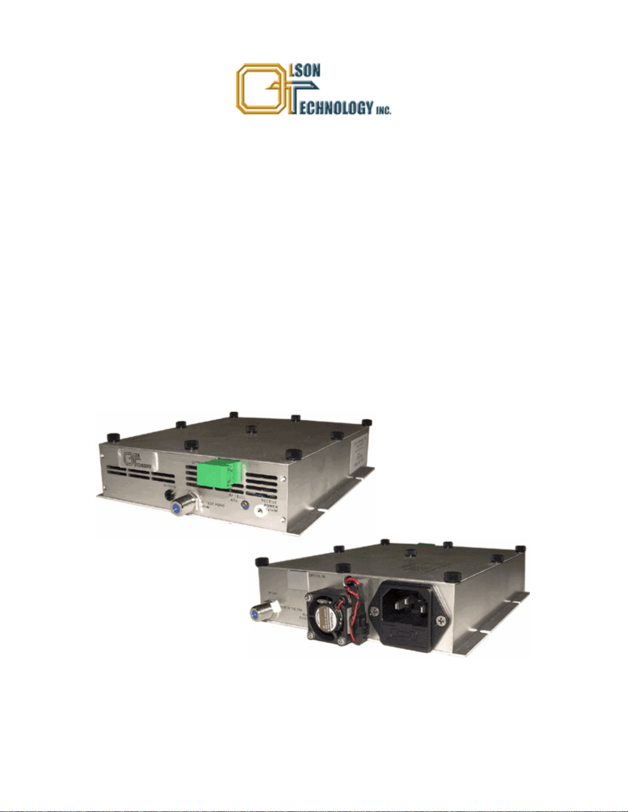
OTOR-300
WIDE BAND LOW COST OPTICAL RETURN RECEIVER
5MHz to 300MHz
-14dBm to +3dBm INPUT
INSTRUCTION MANUAL
Phone:
E-Mail: [email protected]
025-000442 REV X2 4/14/10
(209) 586-1022
(800) 545-1022
Fax:
(209) 586-1026
www.olsontech.com
Page 2

TABLE OF CONTENTS
INTRODUCTION Page 3
INST ALLATION Page 3
Installation / Environmental Considerations Page 3
Optical Connectors and Cleaning Page 4
Setup Procedure Page 4
ACCESSORIES Page 5
RELA TED OLSON TECHNOLOGY PRODUCTS Page 5
T op V iew of OTOR-300 Page 6
SAFETY WARNINGS
LASER RADIATION
The OTOR-300 return receiver receives invisible radiation that can cause
permanent eye damage. A VOID DIRECT EXPOSURE T O BEAM.
NEVER LOOK INTO THE OUTPUT OF A FIBER CONNECTED TO A LASER
TRANSMITTER.
NEVER LOOK INTO OR USE ANY OPTICAL INSTRUMENT TO VIEW THE DIST ANT
END OF A FIBER THA T MAY BE CONNECTED DIRECTL Y OR VIA AN OPTICAL SPLIT,
TO A TRANSMITTER THA T MAY BE OPERA TING. THIS SPECIFICALL Y APPLIES T O
FIBERS THA T ARE T O BE CONNECTED TO RECEIVERS (SUCH AS THE OTOR-300) OR
OTHER DEVICES AT ANY DIST ANCE FROM THE LASER TRANSMITTER.
HIGH VOL T AGE
The inside of the OTOR-300 contains no user serviceable parts. There is exposed high voltage inside this
unit. Only factory service technicians should open the unit with power applied.
FIRE HAZARD
The AC line input fuse is contained in the IEC 320 power input connector. This fuse is a 250V, 0.5A,
5x20mm, slow blow fuse. T o avoid a risk of fire, this fuse should be replaced only with an identically rated fuse.
SHOCK HAZARD
The OTOR-300 is designed for indoor use only . Direct exposure to moisture must be avoided.
025-000442 REV X2
Page 2
Page 3

INTRODUCTION
The OLSON TECHNOLOGY OTOR-300 is a very cost effective indoor wideband optical receiver with an RF
passband of 5 to 300 MHz. This transmitter is intended for indoor applications and combines the receiver and universal
AC power supply in one compact housing that has a footprint of 7.5" x 5.5" x 1.6". This unit has a universal power
supply and will operate from 90 to 240VAC at 50 or 60 Hz and consumes about 10 W atts.
The OTOR-300 is an ideal receiver for the OTPN-1000/OTPT -300 High Sensitivity Indoor Node and will allow for
an optical path loss of up to 18dB. T est points are provided for optical receiver power for the setup and historical
reveiw and for RF output level, again for setup and historical review .
Positive cooling is provided by means of a small, high-MTBF fan, which may be replaced in the field without interrupting
the operation of the unit.
The OTOR-300 has flanges on the bottom to allow mounting it to a flat surface. The available OTLL-RMKIT -1 will
allow mounting up to three of these units in a standard 19" rack.
INST ALLA TION / ENVIRONMENT AL CONSIDERA TIONS
The OTOR-300 is specified to operate from -10°C to +55°C. It will probably not require an air-conditioned environment.
It should be mounted in an adequately ventilated area. Like any other electronic equipment, it will probably have a
longer life span if it is not operated at the upper limit of the temperature range. Installation in wet areas or areas of
extremely high humidity should be avoided. Extremely dirty or dusty areas should be avoided if possible. Objects or
debris should not be allowed to block the openings in the housing or the fan. The unit should not be installed in areas
that are accessible to children.
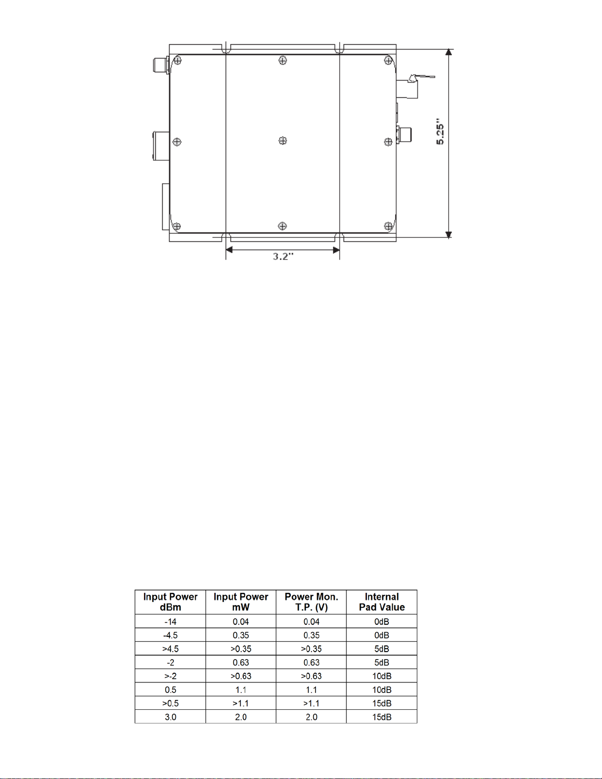
The OTOR-300 may be installed and operated in any position on a flat surface. The unit has four slots in the bottom
plate to accommodate mounting hardware. If mounting requires a wood screw , use #6 or #8 (maximum) pan-head
sheet metal screws. These are commonly available at hardware stores. If mounting with a machine screw (to tapped
holes), use 6-32 pan-head screws.
025-000442 REV X2
Page 3
Page 4
OTOR-300 MOUNTING DIAGRAM
OPTICAL CONNECT ORS AND CLEANING
The standard optical connector is an SC/APC. In order to use FC/APC connectors, you must order a conversion kit,
OTLL-SCFCKIT . The standard optical connector location is on the opposite side from the RF connector . The connector
can be moved to the other side by swapping it with a cover plate. Simply remove the cover with removal of the nine
thumb screws.
The fiber ends can be damaged by the insertion of contaminated connectors. Some types of customer damage to
connectors are not covered under warranty . Fiber connectors should never be left uncovered. Prepackaged alcohol
wipes are the most convenient means of cleaning optical connectors. Clean alcohol and lint free wipes or swabs may
also be used.
SET -UP PROCEDURE FOR OTOR-300
1. The OTOR-300 is best set up with the use of a digital voltmeter monitoring the optical “Receive Power”. The white
test point on the front of the unit indicates the received optical power at 1V/mW of received optical power . Insert the
positive lead into the white test port and negative lead into the black test port to monitor the received power level.
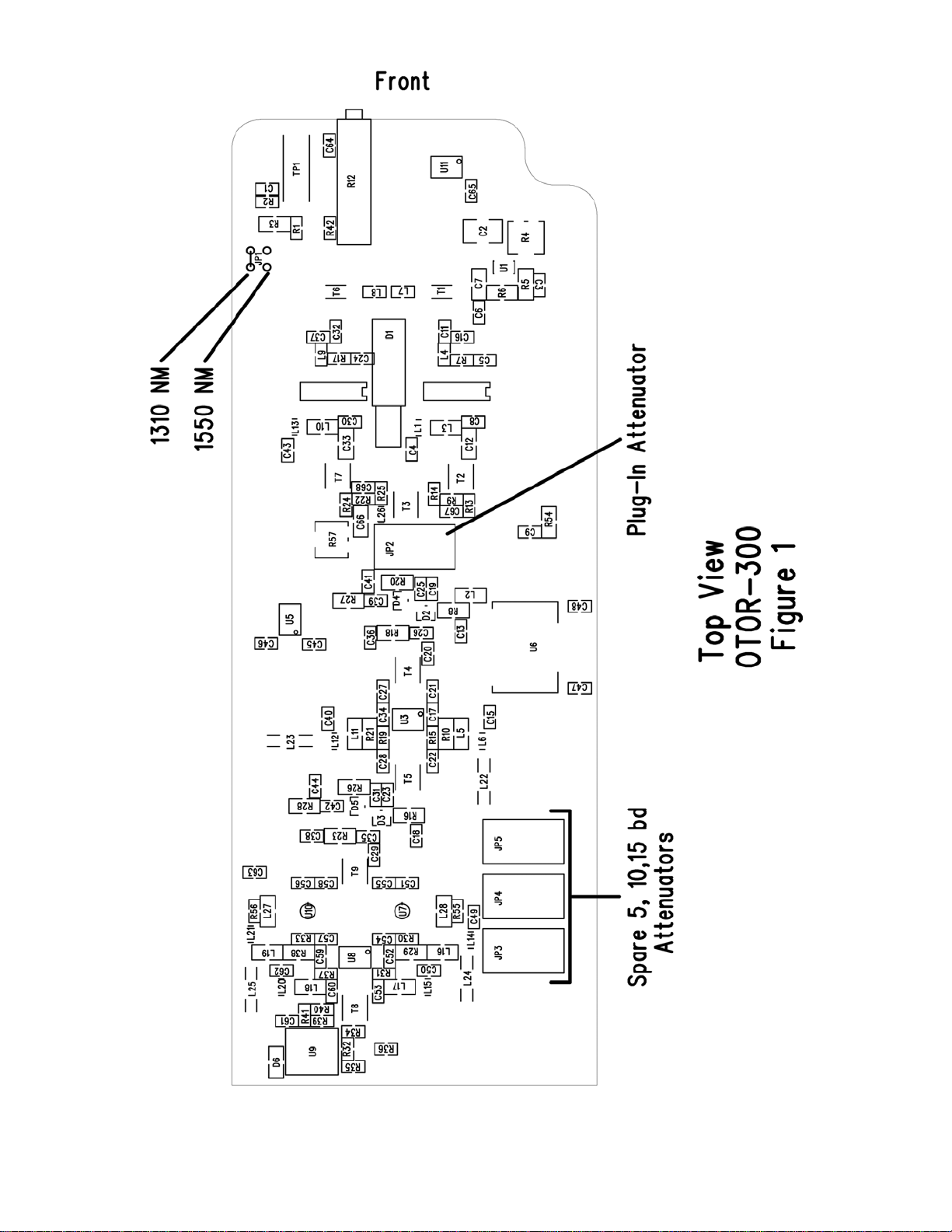
2. Internal to the unit is a plug-in attenuator that optimizes the performance of the unit based upon the received optical
power. The unit is shippied with a 0 dB attenuator installed, but there are also attenuators for 5, 10, & 15dB installed
in storage sockets internal to the unit. It is recommended that the attenuator listed in the table below be installed based
on the received optical power.To change the internal attenuator, remove the thumb screws from the cover . Then
remove the cover and find the plug-in attenuator and the 5, 10, & 15dB pads per diagram of Figure 1.
025-000442 REV X2
Page 4
Page 5
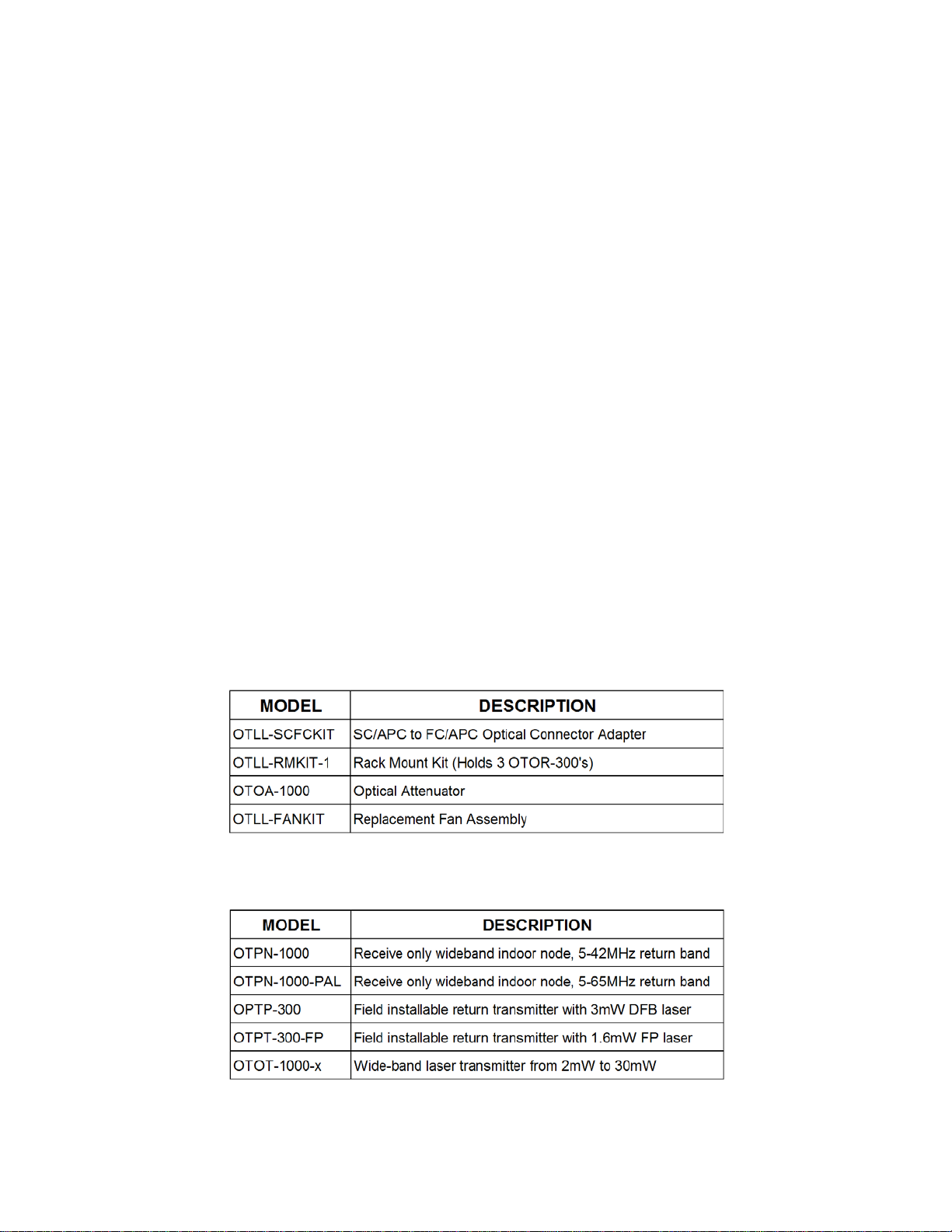
If the optical input power is in excess of +3dBm (2mW), an optical attenuator should be utilized to reduce the input to
+3dBm or lower . The OLSON TECHNOLOGY Model OT OA optical attenuator is ideal for this application.
3. The unit will function at either 1310nm or 1550nm wavelength. However , because the optical detector efficiency is
different at the different wavelengths, there is an internal “Receive Power” calibration jumper plug that needs to be in
the proper position depending upon the input optical wavelength. The diagram of Figure 1 shows the proper position
of this plug for either wavelength. The unit is shipped with the jumper plug in the 1310nm position. For the operators
convenience there is an “Internal Pad Selection Chart” on the cover of the receiver.
4. After the internal attenuator is set for optimum performance, the output level should be set with the front panel “RF
Level Adj.” control. It is recommended that the output level should be set for between +40dBmV and +45dBmV . An
ideal method to set this is with the front panel -20dB “RF T est Point” and the output terminated in the actual load it will
be operating with. If carriers are utilized to set the units output power, adjust the output of the test point for between
+20dBmV and +25dBmV per carrier . If data signals are utilized which appear on a spectrum analyzer as noise, they
can be set up with the output level at the test point between -28dBmV/Hz and -23dBmV/Hz utilizing the noise marker
on the spectrum analyzer . Setting the output level to the levels >-45dBmV will result in the degraded performance.
Although the unit will function at optical input levels as low as -14dBm, the output level attainable will be less than
+45dBmV. +45dBmV will be attainable at optical input levels from typically -11dBmV to -12dBmV. For every 1dB
decrease in optical input power the output level will decrease by 2dB. At -14dBm optical power input, the maximum
output level will be approximately +40dBmV .
ACCESSORIES
RELATED OLSON TECHNOLOGY PRODUCTS
025-000442 REV X2
Page 5
Page 6
025-000442 REV X2
Page 6
 Loading...