

Page 1

LCM-750x3
AGILE VIDEO MODULATOR
INSTRUCTION MANUAL
Phone:
E-Mail: [email protected]
025-000392 REV D 8/20/01
(209) 586-1022
(800) 545-1022
Fax:
(209) 586-1026
www.olsontech.com
Page 2

LCM-750X3
AGILE MODULA TOR
SPECIFICATIONS
EACH MODULE
Output Frequency Range: 48.25 to 749.25MHz in .25 MHz mode
Output Power (Video): +55 dBmV minimum, Adjustable down 10dB
Output Impedance: 75 Ohms
Output Return Loss 15 dB Minimum
Phase Noise > -78dBc/Hz @ 10 KHz
IF Loop Level (Video) +38 dBmV @ 45.75 MHz
IF Loop Level (Audio) +18 to +26dBmV @ 41.25 MHz
Spurious Outputs >55 dB minimum below video carrier, 60 dB typical
Out-of-Band C/N >75 dB below output video carrier, 4 MHz BW
In-Band C/N >63 dB below output video carrier, 4 MHz BW
Frequency Accuracy <+/- 5 KHz
Audio Video Ratio Adjustment From 20 dB to 12 dB below video carrier
Audio Intercarrier Accuracy 4.5 MHz +/- 400 Hz
Video Input 1 V-p-p nominal for 85% modulation
75 Ohm input impedance, F Connector
Audio Input 500mV to 1.4V p-p at 600 Ohm balanced
Power Requirements (one module) +5V @ 780mA, +10V @ 150mA & 24V @ 1mA
COMPLETE UNIT
Power Requirements 90 – 264 VAC, 47 – 63 Hz, 25 W atts
power entry connector
Operating Temperature 0 – 50 degrees C
Chassis Size 1.75” H x 19” W x 9.5” D
025-000392 REV D
Page 2
Page 3

1) INTRODUCTION
The Olson T echnology LCM-750 X3 is a rack mounted chassis 1.75” high that contains 3 LCM-750
frequency agile FCC compatible video modulators. Each modulator provides +55 dBmV output from
48.25 MHz to 750.00 MHz. Channel mode or frequency mode of operation is selectable via a selector
switch accessible from the top plate. Channel modes include CA TV, HRC, IRC and Broadcast. FCC
offsets of +12.5 KHz and +25 KHz are automatically provided depending on the channel plan selected.
The LCM-750 offers the unique Olson T echnology feature of >75 dB out-of-band carrier to noise ratio
along with SA W filtering to provide professional level performance.
Standard composite video and audio or I.F . can be input to the unit.
2) CHANNEL SELECTION
The mode selector switch, SW4 located through the top cover of the LCM-750 allows selection of the
following modes of operation. The selector switch has 10 positions available. The mode switch is set to
position 3, EIA CATV STD, when unit is shipped.
0. CA TV STD (GI ) NTSC
1. HRC ( GI ) NTSC
2. IRC ( GI ) NTSC
3. EIA CA TV STD NTSC
4. EIA HRC NTSC
5. EIA IRC NTSC
6. BROADCAST NTSC
7. MHz +0 MHz
8. MHz +0.25 MHz
9. UNDEFINED
The front panel switches labeled 100’ s, 10’s and 1’ s will adjust the frequency as indicated in modes 7 and
8. In modes 0-6 the front panel switches adjust to indicate the channel selected. For instance, a 0 selected
for the 100’s and 10’ s, with a 5 selected for the 1’ s switch would select channel 5.
When a valid channel is selected, the green LED, located on the front panel will light indicating synthe
sizer lock. The RED LED will flash when an invalid channel is selected and solid when no lock has
occurred. A channel plan is provided at the end of this owners manual.
025-000392 REV D
Page 3
Page 4
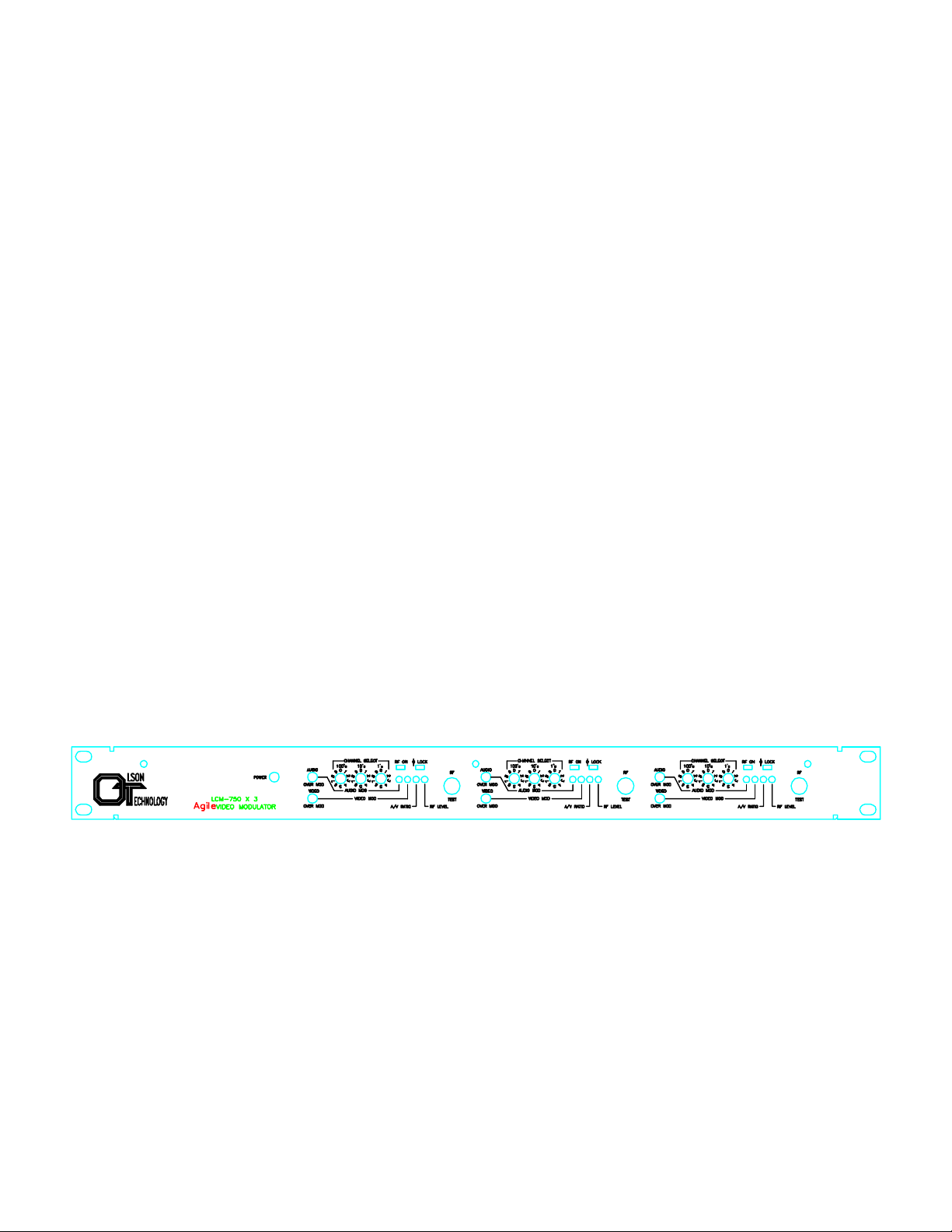
2) RF OUTPUT AND AURAL CARRIER LEVEL ADJUSTMENTS
a. Using a field strength meter or spectrum analyzer, set the video carrier to the desired level with the RF
output “level” adjust pot (typically +55dBmV).
b. T une the field strength meter to the aural carrier, which is located 4.5MHz above the video carrier . Adjust
the aural carrier level control (A/V), to the desired level. This level is typically 15dB below the video
carrier.
3) AUDIO AND VIDEO MODULA TION ADJUSTMENTS
a. The video mod adjustment controls the modulation depth. This adjustment is factory set to 80%
modulation. If this adjustment is turned CW the video overmodulation LED will illuminate, turn CCW until
LED just goes off. This is 80% video modulation.
b. The audio mod adjustment controls audio modulation. Again as with the video mod adjustment, the
modulation threshold is factory preset for 50KHz P-P Deviation. T urn adjustment pot CW until audio
overmodulation LED just comes on. Then turn adjustment CCW until LED just goes off. The LED will
flash occasionally during program audio peaks.
c. Stereo Audio operation requires an external BTSC Stereo Encoder such as Leaming Industries model
SG-100. Also, the internal pre-emphasis must be disabled by moving the shunt on J6 from mono to
stereo. (Older versions require cutting the trace at E1 after removing the top cover .)
4) POWER SUPPLY FUSE
There is 1 user replaceable fuse located on the rear of unit. Ensure unit is disconnected from power before
attempting to replace. Replace with 250V/.5A fuse.
LCM-750 FRONT P ANEL VIEW
025-000392 REV D
Page 4
Page 5
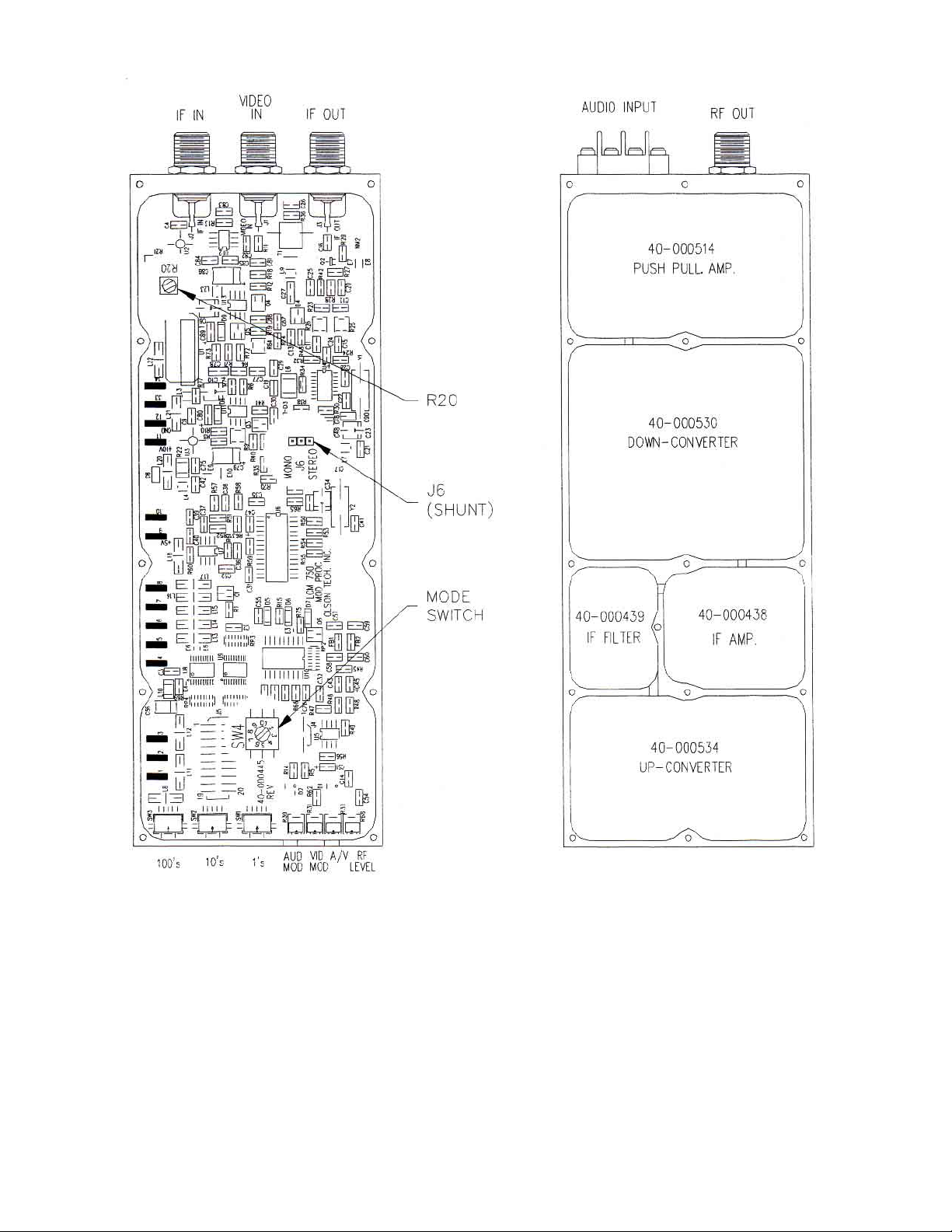
TOP VIEW BOTTOM VIEW
LCM-750 FUNCTION LOCA TION
025-000392 REV D
Page 5
Page 6
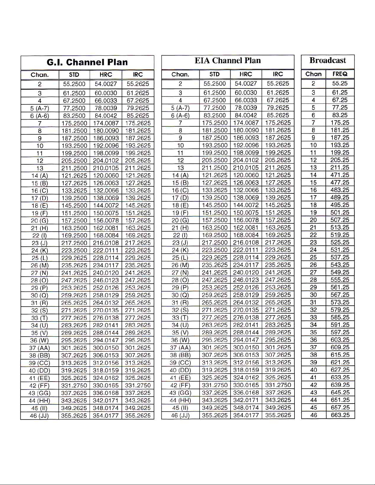
LCM-750 Channel Plans
025-000392 REV D
Page 6
Page 7
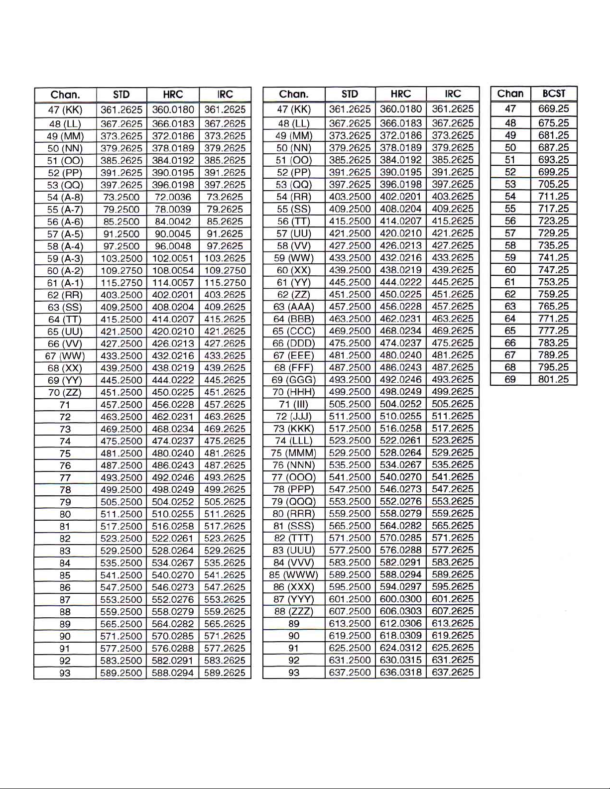
LCM-750 Channel Plans (continued)
025-000392 REV D
Page 7
Page 8
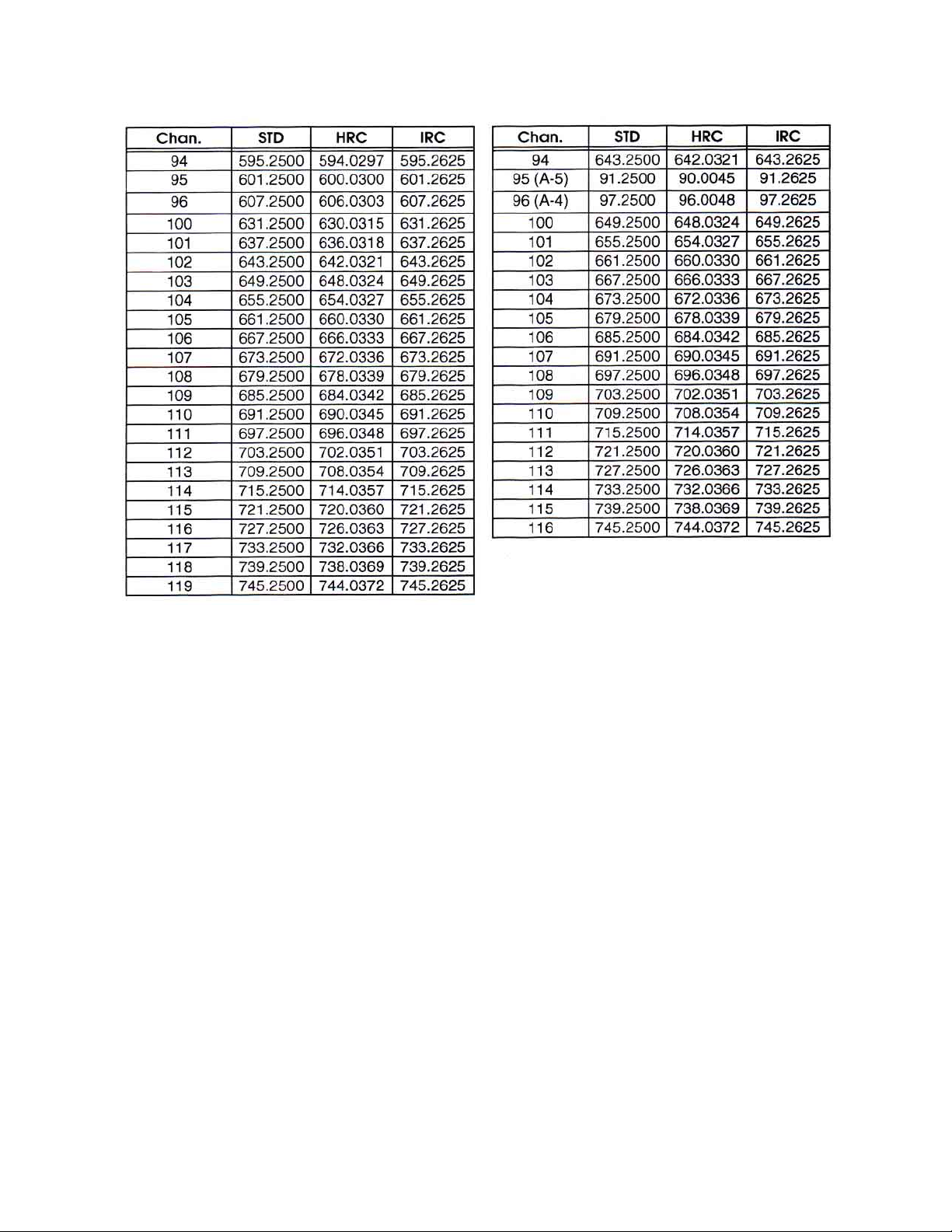
LCM-750 Channel Plans (continued)
025-000392 REV D
Page 8
 Loading...