

Page 1
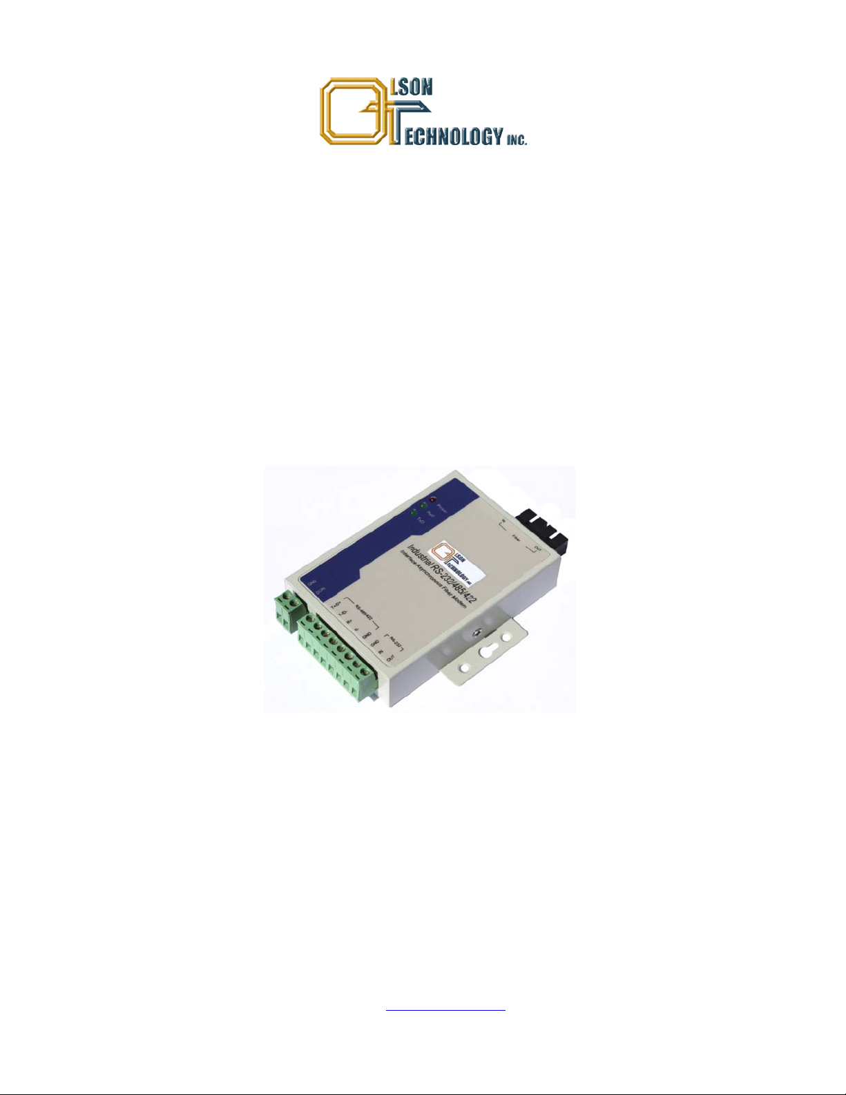
Model OTDL-FOM-01 RS-232/422/485
Serial Fiber Optic Modem
OPERATING MANUAL
24926 Highway 108
Sierra Village, CA 95346
Phone: (800) 545-1022
Fax: (209 586-1022
025-000500 Rev. X1 E-Mail: sales@olsontech.com
10/15/09
Page 2

TABLE OF CONTENTS
SAFETY......................................................................................................................................................................3
Safety Precautions..................................................................................................................................................3
Laser Safety Procedure..........................................................................................................................................3
INTRODUCTION........................................................................................................................................................4
Figure 1 — Typical Application Diagram.........................................................................................................4
PIN CONNECTIONS AND LED INDICATORS .........................................................................................................5
Figure 2 — PIN Locations and LED’s..............................................................................................................5
TECHNICAL SPECIFICATIONS................................................................................................................................6
INSTALLATION .........................................................................................................................................................6
025-000500 Rev. X1 www.olsontech.com
2
Page 3

SAFETY
Safety Precautions
The optical emissions from the units are laser-based and may present eye hazards if improperly used. NEVER USE ANY
KIND OF OPTICAL INSTRUMENT TO VIEW THE OPTICAL OUTPUT OF THE UNIT. Be careful when work-
ing with optical fibers. Fibers can cause painful injury if they penetrate the skin.
Laser Safety Procedure
ALWAYS
read the product data sheet and the laser safety label before powering the product. Note the operation wave-
length, optical output power and safety classifi cat i ons.
If safety goggles or other eye protection is used, be certain that the protection is effective at the wavelength emitted by the
device under test BEFORE
ALWAYS
connect a fiber to the output of the device BEFORE power is applied. Power should never be applied without
applying power.
an attached fiber. If the device has a connector output, a connector should be attached that is connected to a fiber. This
will ensure that all light is confined within the fiber waveguide, virtually eliminating all potential hazard.
NEVER
look at the end of the fiber to see if light is coming out. NEVER! Most fiber optic laser wavelengths (1310nm
and 1550nm) are totally invisible to the unaided eye and will cause permanent damage. Shorter wavelengths lasers (e.g.,
780nm) are visible and are very damaging. Always use instruments, such as an optical power meter, to verify light output.
NEVER, NEVER, NEVER
includes microscopes, eye loupes and magnifying glasses. This WILL
look into the end of a fiber on a powered device with ANY sort of magnifying device. This
cause a permanent and irreversible burn on your
retina. Always double check that power is disconnected before using such devices. If possible, completely disconnect the
unit from any power source.
If you have questions about laser safety procedures, please call Olson Technology before powering your product.
025-000500 Rev. X1 www.olsontech.com
3
Page 4

INTRODUCTION
The OLSON TECHNOLOGY, INC. Model OTDL-FOM-01 RS-232/422/485 Serial Fiber Optic Modem is ideal to connect RTU to HOST or SCADA controllers via optical fiber. The equipment is resistant to the effects of lightning strikes,
power surges, and other electromagnetic interference, providing a reliable data network. The Model OTDL-FOM-01
meets IEA/RS-232 transmission standards at data rates up to 115.2kb/s and RS-422 and RS-485 transmission standards at
data rates up to 500kb/s. The transmission distance is 20km using dual single-mode fibers.
Features include:
• Asynchronous point-to-point data rate of up to 115.2kb/s (RS-232) and 500kb/s (RS-422 and RS-485).
• RS-422/485 port supports 32 nodes with options for up to 128 nodes.
• 1310nm wavelength single-mode transmission up to 20km on two fibers.
• Auto test signal rate and zero delay auto transmit capability.
• Surge protection up to 1500W with 15kV static protection.
• DC power from +9 to +25 Volts.
• Industrial temperature range from –25°C to +70°C.
Figure 1 — Typical Application Diagram
025-000500 Rev. X1 www.olsontech.com
4
Page 5

PIN CONNECTIONS AND LED INDICATORS
Figure 2 — PIN Locations and LED’s
PIN Designation Meaning
Power Interface
GND Ground
DC In 9-25Volt Input
Optical Fiber Interface
IN Optical fiber input.
OUT Optical fiber output.
RS-422/485 Port
T+/D+ RS-422 Send + / RS-485 +
T-/D- RS-422 Send - / RS-485 -
R+ RS-422 Received +
R- RS-422 Received -
GND Ground
RS-232 Port
IN RS-232 Input
OUT RS-232 Output
GND Ground
LED Designation Meaning
Power Unit is powered.
RxD Optical interface is receiving data.
TxD Optical interface is transmitting data.
025-000500 Rev. X1 www.olsontech.com
5
Page 6

TECHNICAL SPECIFICATIONS
Parameter Specification
Standards RS-232, RS-422, RS-485
RS-232 Data Rate 115.2kb/s max.
RS-422/RS-485 Data Rate 500kb/s max.
Transmission Distances RS-232 Port (Copper) - 15m
RS-485/422 Port (Copper) - 1500m
SM Optical Fiber - 20km
Optical Interface SC/UPC Connectors
Data Interface 8-bit Terminal Block
DC Input Voltage +9VDC (Min), +12VDC (Typ), +25VDC (Max)
Current Draw @ +12VDC 80mA
Power Dissipation 1W (Typ), 2W (Max)
Operating Temperature Range -25 to +70°C
Weight 8.1oz. (230g)
Dimensions (L x W x H) 3.942" x 2.72" x 0.86" (100mm x 69mm x 22mm)
INSTALLATION
1. Connect the RS-232 or the RS422 or RS-485 interface to the Model OTDL-FOM-01 at the transmit end. Only one
format may be used at a time.
2. Connect the RS-232 or the RS422 or RS-485 interface to the Model OTDL-FOM-01 at the receive end. Only one for-
mat may be used at a time.
3. Connect the optical fibers to the optical interface on both the transmit and receive ends.
4. Apply power to the unit and check that the Power LED lights up. The RxD and TxD LED’s will light when all the ca-
ble connections are satisfactory.
025-000500 Rev. X1 www.olsontech.com
6
 Loading...