

Page 1

6920-RT-x SERIES RETURN TRANSMITTER
INSTRUCTION MANUAL
INSTRUCTION MANUAL
Phone:
E-Mail: [email protected]
025-370516 REV X2 1/18/06
(209) 586-1022
(800) 545-1022
Fax:
(209) 586-1026
www.olsontech.com
Page 2

TABLE OF CONTENTS
SPECIFICATIONS Page 3
SAFETY WARNINGS Page 4
INTRODUCTION Page 5
INSTALLATION Page 5
Installation/Environmental Considerations Page 5
Optical Connectors and Cleaning Page 5
External Adjustments and Test Points Page 6
Internal Adjustments and Test Points Page 6
Reverse Input Level Setting Page 6
Recommended RF Drive Level Page 6
Channel Loading Page 7
025-370516 REV X2
Page 2
Page 3

Specifications: Return Transmitters: F-P, DFB & CWDM
RF INPUT & PERFORMANCE PARAMETERS:
Frequency Range (+/- 1.0 dB) 5 MHz – 300 MHz
Optical Output (mW) (F-P / DFB / CWDM) 2.0 @ 1310nm /1.0 to 3.0 @ 1310nm / 2.5 @ 1xx0nm**
Return Path NPR > 15dB* F-P: over 37dB NPR; DFB/CWDM over 41dB NPR*
Return Path Threshold -57 dBmV/Hz (@37 or 41dB, as applicable)
* NOTE: As measured with 10dB of fiber (DFB) or 6dB of fiber (F-P) and OTOR-300 High Sensitivity
Return Band Receiver
OPTICAL PARAMETERS:
Return Loss > 60 dB with APC connector
Optical Connector SC/APC standard; FC/APC optional; 8° APC
ELECTRICAL, ENVIRONMENTAL & MECHANICAL PARAMETERS
Dimensions Fit and Form as per the original OEM module
Operating Temperature Range -40 to +70ºC (temperature at the mounting plate)
Powering +25VDC
Power Dissipation < 6 W
025-370516 REV X2
Page 3
Page 4

SAFETY WARNINGS
LASER RADIATION
The 6920-RT-x laser transmitter emits invisible laser radiation that can cause
permanent eye damage. AVOID DIRECT EXPOSURE TO BEAM.
Operate the transmitter only with the proper optical fiber installed in the
transmitter optical connector. The power to the 6920-RT-x should be turned off whenever the optical connector is
opened or exposed (as when the fiber connection is being installed or removed from the transmitter connector).
NEVER USE ANY OPTICAL INSTRUMENT TO VIEW THE OUTPUT OF THE LASER
TRANSMITTER. “OPTICAL INSTRUMENT” INCLUDES MAGNIFYING GLASSES, ETC.
NEVER LOOK INTO THE OUTPUT OF THE LASER TRANSMITTER
NEVER LOOK INTO THE OUTPUT OF A FIBER CONNECTED TO A LASER
TRANSMITTER.
NEVER LOOK INTO OR USE ANY OPTICAL INSTRUMENT TO VIEW THE DISTANT
END OF A FIBER THAT MAY BE CONNECTED DIRECTLY OR VIA AN OPTICAL SPLIT,
TO A TRANSMITTER THAT MAY BE OPERATING. THIS SPECIFICALLY APPLIES TO
FIBERS THAT ARE TO BE CONNECTED TO RECEIVERS OR
OTHER DEVICES AT ANY DISTANCE FROM THE LASER TRANSMITTER.
SHOCK HAZARD
Care should be used when installing the 6920-RT-x to prevent shock and
injury as there are voltages within the Node which exceed 48 VAC.
025-370516 REV X2
Page 4
Page 5
INTRODUCTION
The Olson Technology Inc. 6920-RT-x is a high quality, cost effective, Return Transmitter module designed around the latest
optical transmitter technology. The 6920-RT-x is a series of replacement broadband return transmitters for the 6920 series of
optical nodes. The performance is equivalent to or better than that of the original transmitters. It can be used in the same
applications as the original transmitter. The basic standard models are listed below. There are many other custom versions and
single to dual upgrades available. Please consult Olson Technology for our latest product list. ALL standard units have SC/APC
connectors.
MODEL DESCRIPTION
6920-RT-2-SA/302 2mW, 1310nm FP
6920-RT-2-SA/303 2mW, 1310nm isolated FP
6920-RT-5-SA/304 2mW, 1310nm DFB
6920-RT-5-SA/505 2mW, 1550nm DFB
6920-RT-5-SA/5xx 2mW, 1550nm DFB CWDM
xx=47,49,51,53,55,57,59 or 61 (middle 2 digits of CWDM wavelength)
Note: Olson Technology does not recommend or support the use of FP lasers for VOIP or analog video.
The 6920-RT-x receives preconditioned +24 VDC from the Node and plugs directly into the preexisting locations within the Node.
The primary RF connection is made through the RF connector on the bottom of the transmitter. The transmitter can be ordered
with an optical connection that will match the factory setup. Heat transfer for the 6920-RT-x is provided via the bottom surface of
the module to the Node housing for full outdoor temperature operation.
INSTALLATION / ENVIRONMENTAL CONSIDERATIONS
The 6920-RT-x operates with an exterior temperature on the Node of -40 to + 60°C. However, like any other electronic device, it will
probably have a longer life span if it is not operated at the upper limit of it's temperature range continuously. Installation of the
6920-RT-x should be done such that water, dirt and other contaminates do not enter either the Node or the module. Do not install
equipment in locations that are accessible by either children or other unqualified personnel. This unit is meant to be fieldinstalled into the SA6920 Optical Node by qualified field service technicians.
The 6920-RT-x installs in the lid of the node. The transmitter can be hot swapped without damage to the module or node. The
retaining screws should be simultaneously worked down. Do not fully tighten one screw before partially engaging and tightening the other one.
Excess fiber should be coiled around the fiber organizer. Care should be exercised to avoid breaking or kinking the fiber.
CAUTION: The “standard” units all use angle polished optical connectors (APC) with green bodies or boots. Some configura-
tions may use flat/ultra polished connectors (UPC) with blue bodies or boots. You can not mate the two different types and
achieve satisfactory performance. There is a second bushing already installed to allow for simple upgrade to dual transmitters in
a single housing.
025-370516 REV X2
Page 5
Page 6
EXTERNAL ADJUSTMENTS AND TEST POINTS
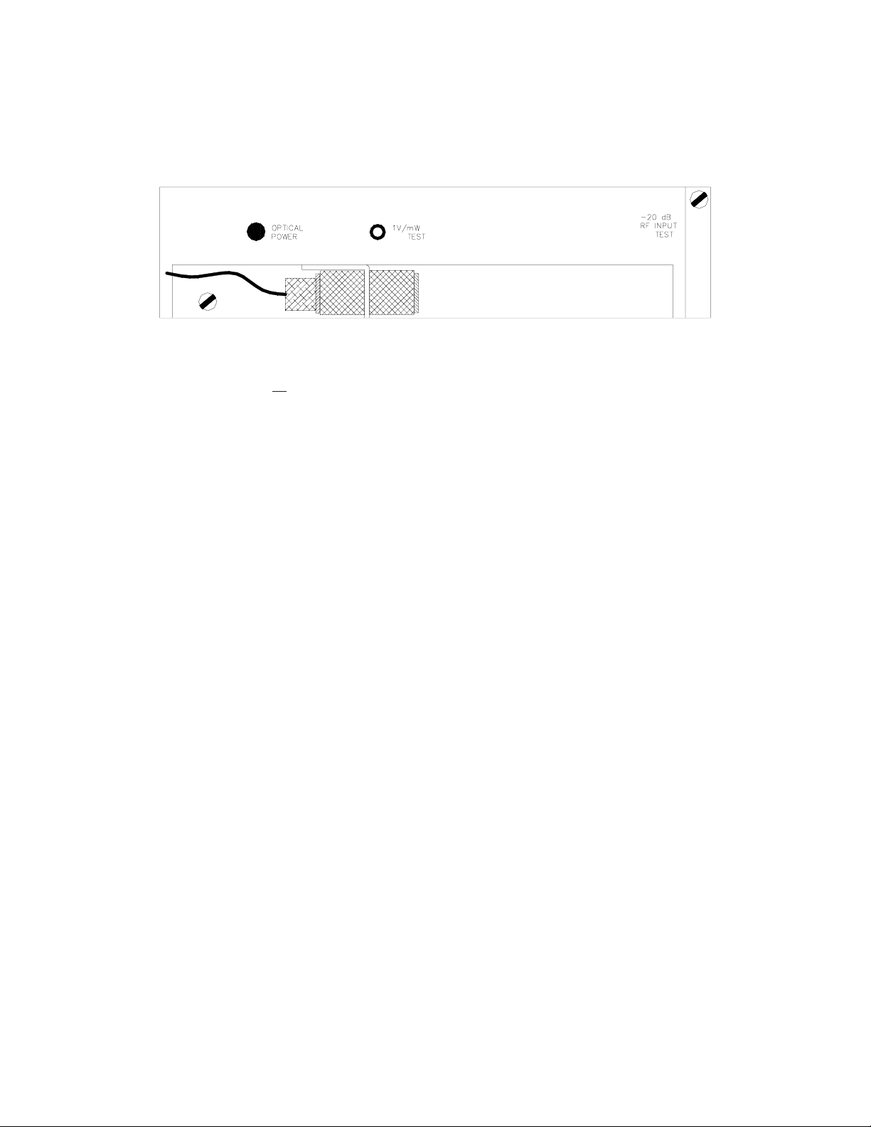
There are no external adjustments. There is one test point that monitors optical output power. This is scaled to 1V/mW and
should be measured with a high impedance voltmeter. There is a red/green LED that will be green when the laser optical output
power is OK and red if it is out of spec. There is a -20 dB return RF input test point which is normally accessed through the
outside of the housing using a type ‘G’ connector.
INTERNAL ADJUSTMENTS AND TEST POINTS
There are no internal test points and no internal adjustments that would normally be performed in the field. The backup RF and
status monitoring options require some internal changes. Due to the variety of these that are available, please consult Olson
Technology. CAUTION: removing the cover allows access to static sensitive components. These operations should be per-
formed only at a static controlled location.
REVERSE INPUT RF LEVEL SETTING
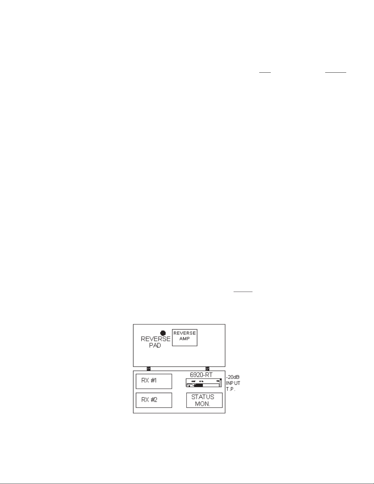
The return RF level should be set using the reverse pad on the 6920 main board. The internal pad in the return transmitter is for
laser OMI matching, not for level setting. Monitor the –20db test point on the transmitter and adjust the reverse pad on the 6920
main board for the correct level from the RF drive table for the transmitter type being used.
RECOMMENDED RF DRIVE LEVEL
Laser Transmitter Option RF Input RF Input –20db Test Point
6920-RT-2-302/2mW (FP) +20dBmV / Chan 0 dBmV / Chan
6920-RT-5-304/2mW (DFB) +27.5dBmV / Chan +7.5dBmV / Chan
025-370516 REV X2
Page 6
Page 7
CHANNEL LOADING
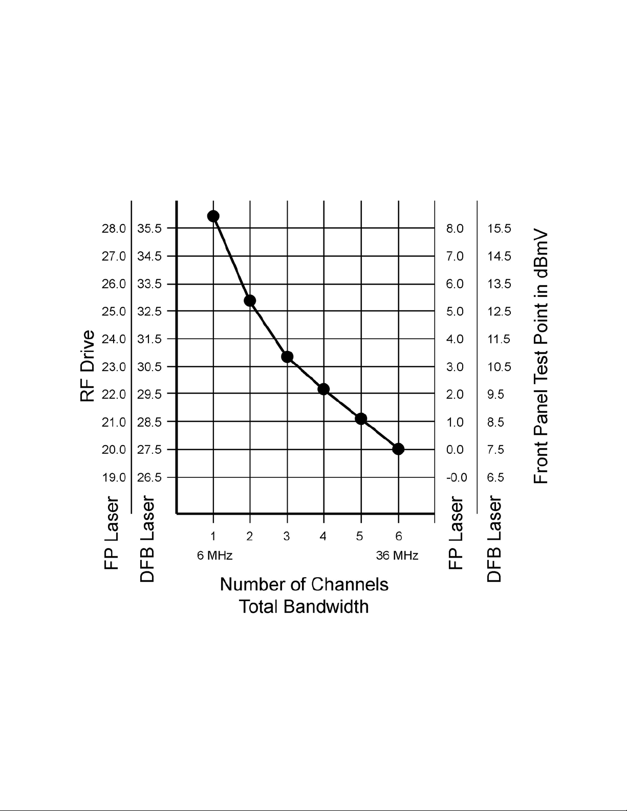
The optimum RF input level for the 6920-RT-x is 27.5dBmV per channel if equiped with an DFB laser and with a
standard loading of six CW channels. Or 20dBmV per channel if equipped with an FP laser. The chart below shows
the change in RF input level according to the amount and type of channel loading. The chart shows on the right what
the RF input level is according to the -20dB test point. On the left, the RF input in dBmV is shown for FP and DFB
type lasers. If loading with data channels only (QPSK, QAM) refer to the amount of total bandwidth the data
channels are consuming. 27.5dBmV per CW channel is equivalent to -41.18dBmV/Hz, while 20dBmV per channel
is equal to -55.68dBmV/Hz.
025-370516 REV X2
Page 7
 Loading...