

Page 1

FRMUC-AR440 KIT
FREQUENCY MUL TIPLIER UP CONVER TER
FOR THE AR-400 GEMINI NODE
INSTRUCTION MANUAL
Phone:
E-Mail: [email protected]
025-000477 REV x1 10/23/03
(209) 586-1022
(800) 545-1022
Fax:
(209) 586-1026
www.olsontech.com
Page 2

TABLE OF CONTENTS
SPECIFICA TIONS Page 3
INST ALLA TION GUIDE Page 4
OPERA TIONAL SETUP
1. Operational setup for RF Page 6
025-000477 REV x1
Page 2
Page 3
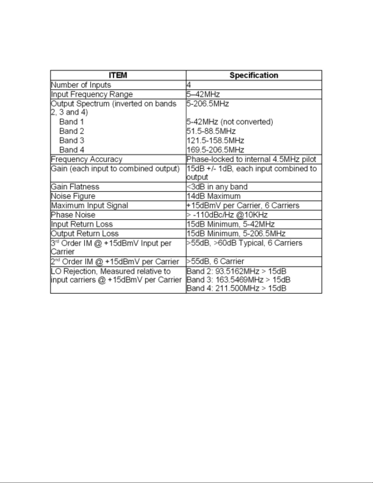
FRMUC-AR440 Specifications
025-000477 REV x1
Page 3
Page 4
The Arris 400 Gemini node used in this installation pr oceedure may differ in configuration, adjustments
to the install proceedure may required.
NOTE: The FRMUC-AR440 kit uses 75
Ω Ω
Ω type SMB connections on the RF cables. These connections
Ω Ω
(and those they mate with) can be damaged if inadvertantly abused. Use caution in handling and plugging/
unplugging these. Always press them straight in and pull them straight out.
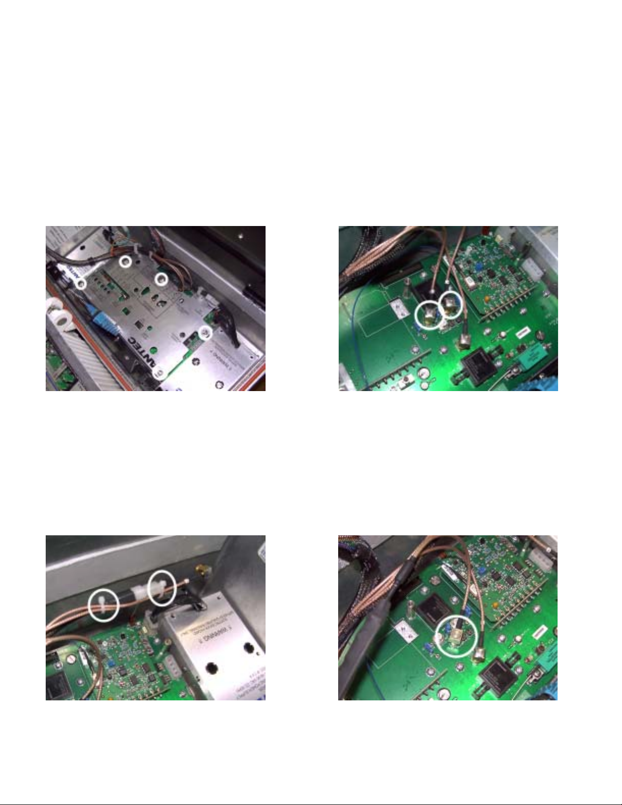
Step 1: Loosen the 5 captive screws holding on the metal cover underneath the metal tray . (See Figure 1)
Figure 1: Figure 2:
Step 2: Remove the cover plate.
Step 3: Locate TX “A” IN and TX “B” IN port (See Figure 2). Remove the two Standard SMB cables from these
ports. Zip tie the two cables to the power supply cables to keep them out of the way (Figure 3). Then plug in the
Standard SMB cable which is supplied with the kit, at SWITCHED IN. (See Figure 4). Then place the metal cover
back into postion. Be sure to not pinch any fiber optic cable that may be in the way .
Figure 3: Figure 4:
025-000477 REV x1
Page 4
Page 5
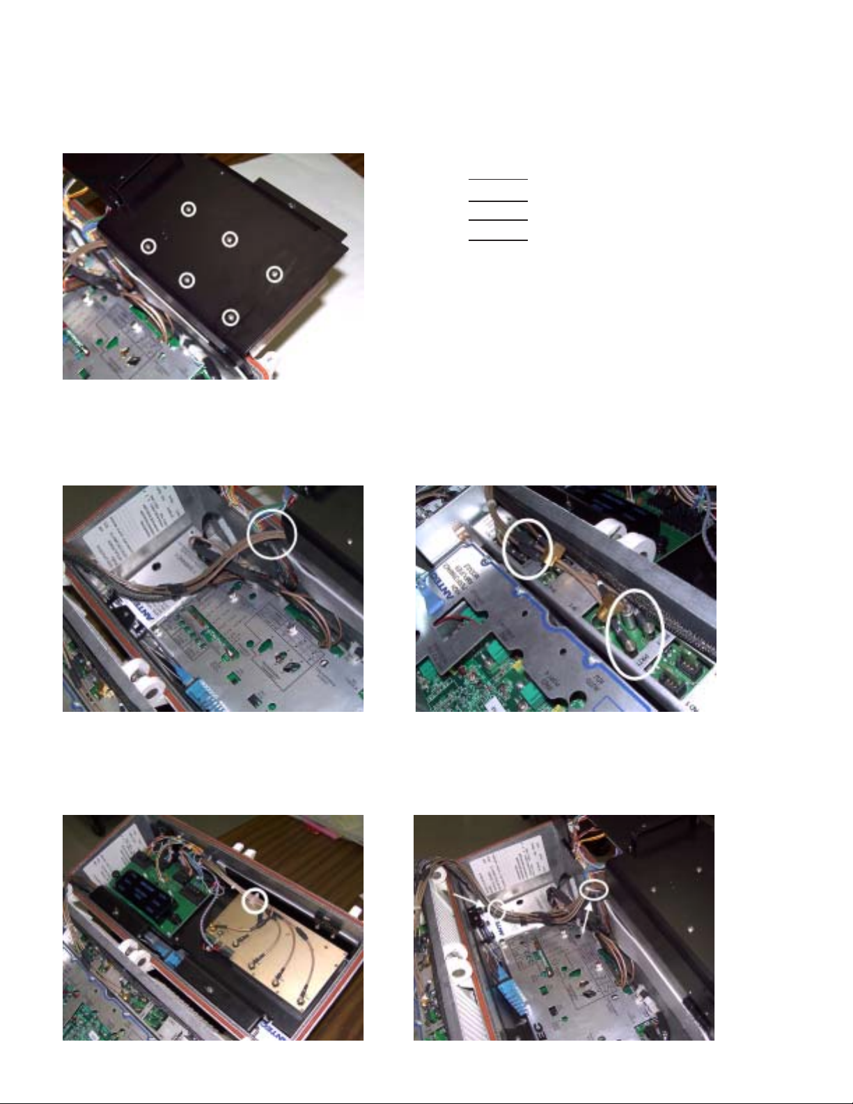
Step 4: Install the upconverter onto the top of the metal tray using the 6 screws which attach from the under side as
shown and tighten firmly (See Figure 5). Plug the transmitter cable assembly from SWITCHED IN into the RF
OUT port on the upconverter
Figure 5: Figure 6:
Up-Converter
Band 1
Band 2
Band 3
Band 4
P7RCM Module
Port 1
Port 3
Port 4
Port 6
Step 5: Feed the RF cables through the slot between the top tray and the main housing as shown (Figure 7). The
cables are marked on each end to show where they connect. (Figure 6) Example: A cable marked with 2 and 3, will
connect to band 2 on the upconverter, and port 3 on the P7RCM module (Figure 8).
Figure 7: Figure 8:
Step 6: The RF cables can now be zip tied into place. There is a white cable hold down, place the RF cables into
this, and slide one of the supplied zip ties through the two slots in the hold down, and around the cables, tighten until
snug (Figure 9). The RF cables are then secured to the wirering harness where shown. (Figure 10)
Figure 9: Figure 10:
025-000477 REV x1 Page 5
Page 6
Step 9: Carefully check cable flexing and fit by closing the housing several times. Arrange cables as necessary to
ensure there are no problems. Be sure cables do NOT get pinched by the black tray that the upconverter mounts
to.
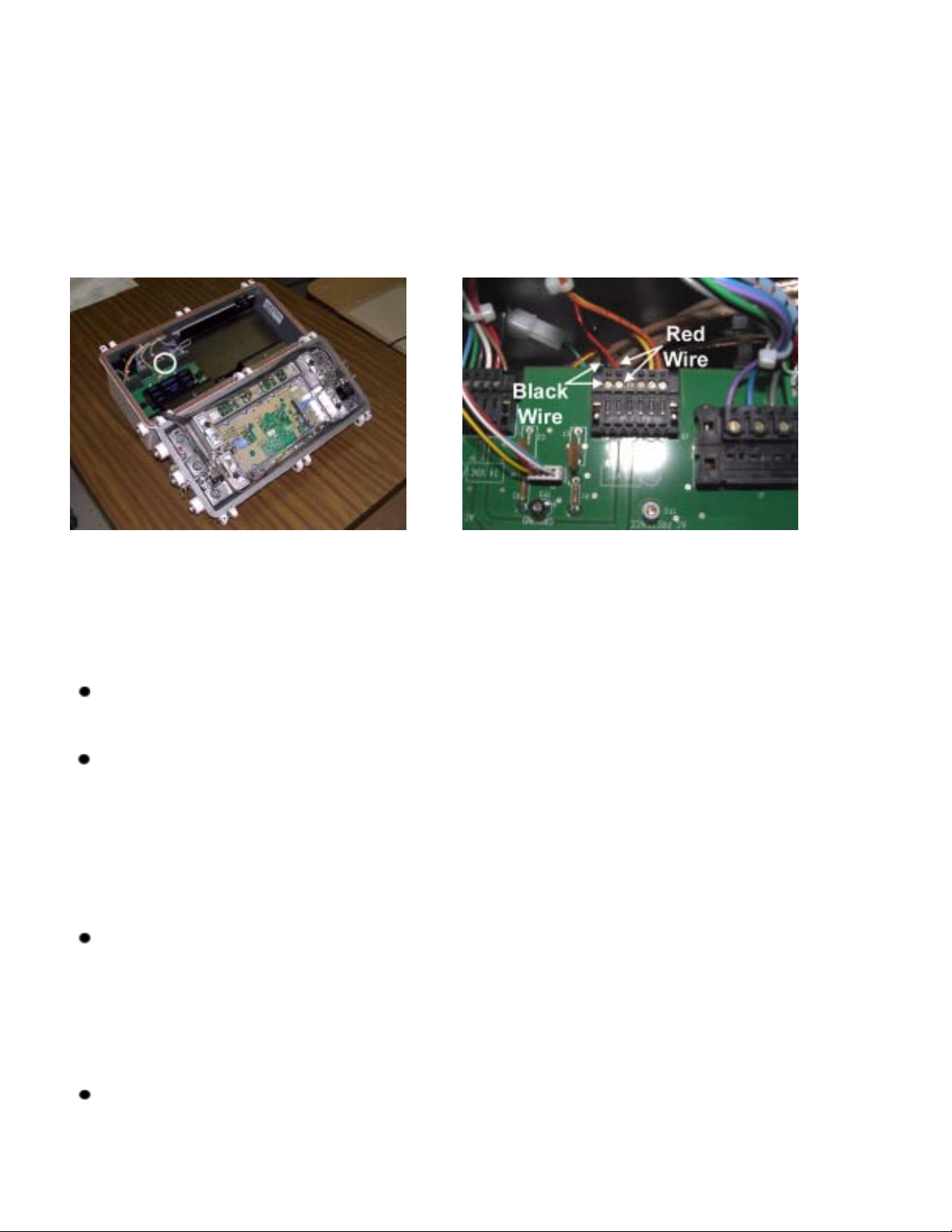
Step 10: Connect the two power lead wires coming from the upconverter to the terminals on the power
distribution board located at J3 (Figure 9). Loosen the screw and slide the black wire (Ground) into the left most
connection as shown. (Figure 10). The red wire (24V) will go into the slot just to the right of the ground as shown
(Figure 10)
Figure 9: Figure 10:
OPERATIONAL SETUP - RF
The converter accepts four separate return inputs, one from each feeder leg. It up-converts three of them to
three different bands, and combines them with one un-converted band. This combination of four bands plus a
pilot carrier at 4.5MHz is fed into the laser transmitter of the Arris Gemini Node for return transmission via fiber.
If the FRMUC-AR440 is installed properly , the frequencies of the four bands and their relationship to the four
feeder legs are as follows:
FEEDER POR T THREE BAND ONE 5MHz to 42MHz
FEEDER PORT FOUR BAND TWO 51.5MHz to 88.5MHz
FEEDER PORT FIVE BAND THREE 121.5MHz to 158.5MHz
FEEDER POR T SIX BAND FOUR 169.5MHz to 206.5MHz
The return carrier levels from each feeder leg into the converter should be checked and adjusted if necessary .
The levels from the four feeders can be checked on the P7RCM module at the 4 reverse path test points.
The specification for MAXIMUM carrier level into each converter band is defined as +15dBmV per (CW)
carrier with six carriers present. For best return optical system performance, the input level should be a MINIMUM of +12dBmV per (CW) carrier with six carriers present. The carrier levels may be adjusted as necessary
to provide channel-loading equivalent to the six-carrier levels. Padding can be applied at the P AD 1 to Pad 4
locations.
Remember to factor-in the test point value when making carrier level measurement at the test points. The levels
mentioned above are ACTUAL levels at the feeder legs/converter inputs.
025-000477 REV x1 Page 6
Page 7
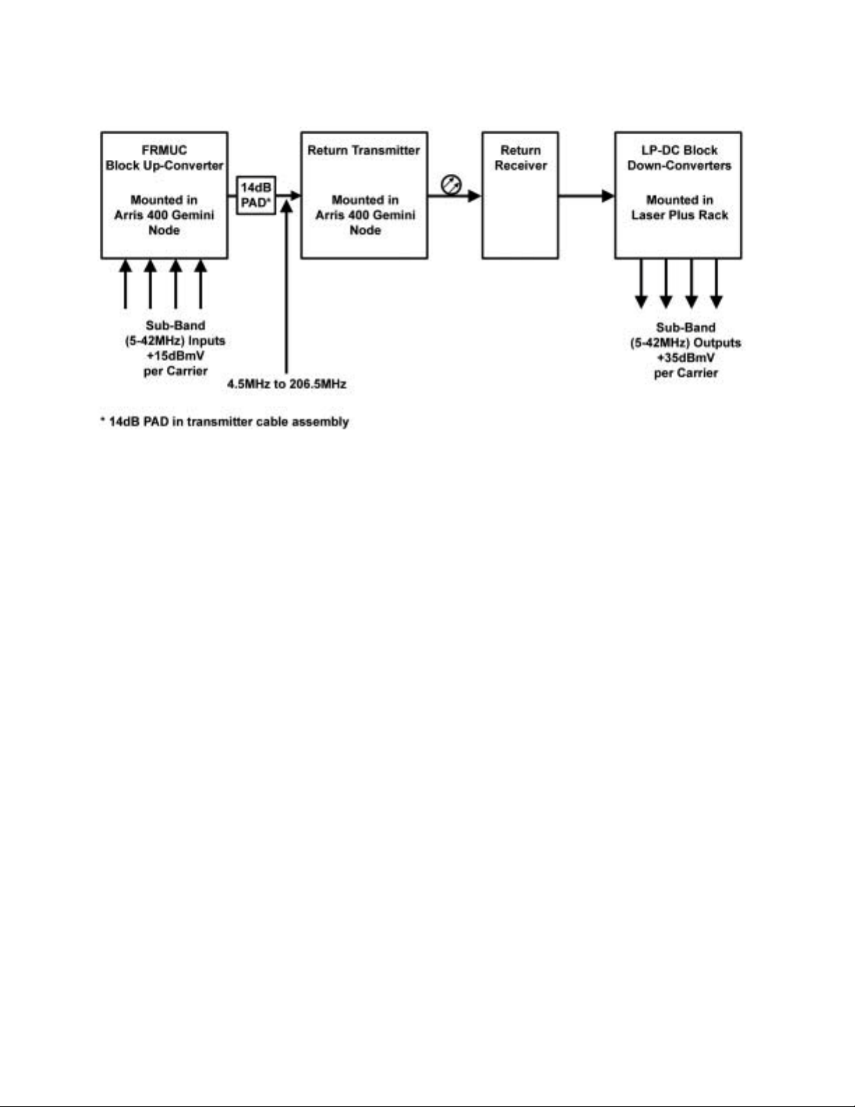
Operational System Diagram
025-000477 REV x1 Page 7
 Loading...