


 Loading...
ML5720/ML5721/ML5790/ML5791
Technical Reference Guide

PREFACE
Every effort has been made to ensure that the information in this document is complete, accurate, and up-to-date. The manufacturer assumes no responsibility for the results of errors beyond its control. The manufacturer also cannot guarantee that changes in software and equipment made by other manufacturers and referred to in this guide will not affect the applicability of the information in it. Mention of software products manufactured by other companies does not necessarily constitute endorsement by the manufacturer.
While all reasonable efforts have been made to make this document as accurate and helpful as possible, we make no warranty of any kind, expressed or implied, as to the accuracy or completeness of the information contained herein.
The most up-to-date drivers and manuals are available from the web site: http://www.okiprintingsolutions.com
07118001 Iss.01 Copyright © 2011 Oki Europe Ltd. All rights reserved. Oki is a registered trademark of Oki Electric Industry Company, Ltd. Oki Printing Solutions is a trademark of Oki Data Corporation.
Energy Star is a trademark of the United States Environmental Protection Agency. Microsoft, MS-DOS and Windows are registered trademarks of Microsoft Corporation. Apple, Macintosh, Mac and Mac OS are registered trademarks of Apple Inc.
Other product names and brand names are registered trademarks or trademarks of their proprietors.
As an ENERGY STAR Program Participant, the manufacturer has determined that this product meets the ENERGY STAR guidelines for energy efficiency.
This product complies with the requirements of the Council Directives 2004/ 108/EC (EMC), 2006/95/EC (LVD) and 2009/125/EC (ErP) as amended where applicable on the approximation of the laws of the member states relating to electromagnetic compatibility, low voltage and energy related product.
This product complies with EN55022 Class B. However, when fitted with the optional network interface card or optional cut-sheet feeder, compliance to EN55022 is Class A. In a domestic environment this configuration may cause radio interference, in which case the user may be required to take adequate control measures.
The following cables were used to evaluate this product to achieve EMC directive 2004/108/EC compliance and configurations other than this may affect that compliance.
CABLE TYPE |
LENGTH |
CORE |
SHIELD |
|
(METRE) |
|
|
|
|
|
|
Power |
1.8 |
|
|
|
|
|
|
USB |
5.0 |
|
|
|
|
|
|
Serial |
2.1 |
|
|
|
|
|
|
Parallel |
2.0 |
|
|
|
|
|
|
LAN |
5.0 |
|
|
|
|
|
|
Preface > 2

MANUFACTURER
Oki Data Corporation, 4-11-22 Shibaura, Minato-ku, Tokyo 108-8551,
Japan
IMPORTER TO THE EU/AUTHORISED REPRESENTATIVE
Oki Europe Limited (trading as Oki Printing Solutions)
Blays House
Wick Road Egham
Surrey, TW20 0HJ
United Kingdom
For all sales, support and general enquiries contact your local distributor.
ENVIRONMENTAL INFORMATION
Manufacturer > 3
CONTENTS
Preface . . . . . . . . . . . . . . . . . . . . . . . . . . . . . . . . . . . . . . . . . . . . . . . . . . .2 Manufacturer. . . . . . . . . . . . . . . . . . . . . . . . . . . . . . . . . . . . . . . . . . . . . . .3 Importer to the EU/authorised representative. . . . . . . . . . . . . . . . . . . . .3 Environmental Information. . . . . . . . . . . . . . . . . . . . . . . . . . . . . . . . . . . .3 Contents . . . . . . . . . . . . . . . . . . . . . . . . . . . . . . . . . . . . . . . . . . . . . . . . . .4 Notes, cautions and warnings. . . . . . . . . . . . . . . . . . . . . . . . . . . . . . . . . .7
About this guide . . . . . . . . . . . . . . . . . . . . . . . . . . . . . . . . . . . . . . . . . . . .8
Online usage. . . . . . . . . . . . . . . . . . . . . . . . . . . . . . . . . . . . . . . . . . . . . 8 Printing pages. . . . . . . . . . . . . . . . . . . . . . . . . . . . . . . . . . . . . . . . . . . . 9
Introduction . . . . . . . . . . . . . . . . . . . . . . . . . . . . . . . . . . . . . . . . . . . . . .10
Features. . . . . . . . . . . . . . . . . . . . . . . . . . . . . . . . . . . . . . . . . . . . . . . .10 Standard configuration. . . . . . . . . . . . . . . . . . . . . . . . . . . . . . . . . . . . . .12 Options . . . . . . . . . . . . . . . . . . . . . . . . . . . . . . . . . . . . . . . . . . . . . . . .12 Identifying component parts . . . . . . . . . . . . . . . . . . . . . . . . . . . . . . . . . .13 Front view . . . . . . . . . . . . . . . . . . . . . . . . . . . . . . . . . . . . . . . . . . . .13 Internal view . . . . . . . . . . . . . . . . . . . . . . . . . . . . . . . . . . . . . . . . . .14 Rear view . . . . . . . . . . . . . . . . . . . . . . . . . . . . . . . . . . . . . . . . . . . . .14
Interface specifications. . . . . . . . . . . . . . . . . . . . . . . . . . . . . . . . . . . . . .15
IEEE1284 parallel interface specifications . . . . . . . . . . . . . . . . . . . . . . . . .15 Connectors and cable. . . . . . . . . . . . . . . . . . . . . . . . . . . . . . . . . . . . .15 Parallel interface signals. . . . . . . . . . . . . . . . . . . . . . . . . . . . . . . . . . .15 Parallel interface levels . . . . . . . . . . . . . . . . . . . . . . . . . . . . . . . . . . .16 Parallel interface circuits . . . . . . . . . . . . . . . . . . . . . . . . . . . . . . . . . .16 Parallel interface timing chart . . . . . . . . . . . . . . . . . . . . . . . . . . . . . . .16 Support mode. . . . . . . . . . . . . . . . . . . . . . . . . . . . . . . . . . . . . . . . . .16
Universal Serial Bus (USB) . . . . . . . . . . . . . . . . . . . . . . . . . . . . . . . . . . .17 Connectors . . . . . . . . . . . . . . . . . . . . . . . . . . . . . . . . . . . . . . . . . . . .17 Cable . . . . . . . . . . . . . . . . . . . . . . . . . . . . . . . . . . . . . . . . . . . . . . . .17 USB interface signals . . . . . . . . . . . . . . . . . . . . . . . . . . . . . . . . . . . . .17 Mode and class of device . . . . . . . . . . . . . . . . . . . . . . . . . . . . . . . . . .17 Data signalling rate . . . . . . . . . . . . . . . . . . . . . . . . . . . . . . . . . . . . . .17 Interface circuit. . . . . . . . . . . . . . . . . . . . . . . . . . . . . . . . . . . . . . . . .18 Signal level. . . . . . . . . . . . . . . . . . . . . . . . . . . . . . . . . . . . . . . . . . . .18 Timing chart . . . . . . . . . . . . . . . . . . . . . . . . . . . . . . . . . . . . . . . . . . .19
Option interface specifications. . . . . . . . . . . . . . . . . . . . . . . . . . . . . . . . .21 General specifications . . . . . . . . . . . . . . . . . . . . . . . . . . . . . . . . . . . .21 Interface signals . . . . . . . . . . . . . . . . . . . . . . . . . . . . . . . . . . . . . . . .22 Electrical characteristics . . . . . . . . . . . . . . . . . . . . . . . . . . . . . . . . . . .22 Interface timing charts. . . . . . . . . . . . . . . . . . . . . . . . . . . . . . . . . . . .24 Receiving margin. . . . . . . . . . . . . . . . . . . . . . . . . . . . . . . . . . . . . . . .24 Description of communication procedures. . . . . . . . . . . . . . . . . . . . . . .24 Interface control code . . . . . . . . . . . . . . . . . . . . . . . . . . . . . . . . . . . .24 Local test function . . . . . . . . . . . . . . . . . . . . . . . . . . . . . . . . . . . . . . .26
Operator interface. . . . . . . . . . . . . . . . . . . . . . . . . . . . . . . . . . . . . . . . . .27
Operator panel functions . . . . . . . . . . . . . . . . . . . . . . . . . . . . . . . . . . . .27 Print mode . . . . . . . . . . . . . . . . . . . . . . . . . . . . . . . . . . . . . . . . . . .28 Hex Dump mode, Menu mode, Test mode . . . . . . . . . . . . . . . . . . . . . .30 Indicators . . . . . . . . . . . . . . . . . . . . . . . . . . . . . . . . . . . . . . . . . . . . . .31 Alarm/error indications . . . . . . . . . . . . . . . . . . . . . . . . . . . . . . . . . . . . .33 Recoverable alarms . . . . . . . . . . . . . . . . . . . . . . . . . . . . . . . . . . . . . .33 Unrecoverable alarms . . . . . . . . . . . . . . . . . . . . . . . . . . . . . . . . . . . .36 Menu selection . . . . . . . . . . . . . . . . . . . . . . . . . . . . . . . . . . . . . . . . . . .37 Overview . . . . . . . . . . . . . . . . . . . . . . . . . . . . . . . . . . . . . . . . . . . . .37
Contents > 4
Operation . . . . . . . . . . . . . . . . . . . . . . . . . . . . . . . . . . . . . . . . . . . . .37 Menu items. . . . . . . . . . . . . . . . . . . . . . . . . . . . . . . . . . . . . . . . . . . .38 Self test printing . . . . . . . . . . . . . . . . . . . . . . . . . . . . . . . . . . . . . . . . . .53 Rolling ASCII self test printing . . . . . . . . . . . . . . . . . . . . . . . . . . . . . . . .54 Hexadecimal Dump mode. . . . . . . . . . . . . . . . . . . . . . . . . . . . . . . . . . . .55 Overview . . . . . . . . . . . . . . . . . . . . . . . . . . . . . . . . . . . . . . . . . . . . .55 Operation . . . . . . . . . . . . . . . . . . . . . . . . . . . . . . . . . . . . . . . . . . . . .55 Function . . . . . . . . . . . . . . . . . . . . . . . . . . . . . . . . . . . . . . . . . . . . . .56 Automatic paper loading . . . . . . . . . . . . . . . . . . . . . . . . . . . . . . . . . . . .56 Auto-parking . . . . . . . . . . . . . . . . . . . . . . . . . . . . . . . . . . . . . . . . . . . .57 Form tear-off . . . . . . . . . . . . . . . . . . . . . . . . . . . . . . . . . . . . . . . . . . . .57 Function . . . . . . . . . . . . . . . . . . . . . . . . . . . . . . . . . . . . . . . . . . . . . .57 Set-up . . . . . . . . . . . . . . . . . . . . . . . . . . . . . . . . . . . . . . . . . . . . . . .57 Action . . . . . . . . . . . . . . . . . . . . . . . . . . . . . . . . . . . . . . . . . . . . . . .57 Print position . . . . . . . . . . . . . . . . . . . . . . . . . . . . . . . . . . . . . . . . . . . .58 Quiet printing . . . . . . . . . . . . . . . . . . . . . . . . . . . . . . . . . . . . . . . . . .58 High-copy printing. . . . . . . . . . . . . . . . . . . . . . . . . . . . . . . . . . . . . . .58
Command descriptions . . . . . . . . . . . . . . . . . . . . . . . . . . . . . . . . . . . . . .59
ML5720/ML5721 . . . . . . . . . . . . . . . . . . . . . . . . . . . . . . . . . . . . . . . . . .59 Horizontal control . . . . . . . . . . . . . . . . . . . . . . . . . . . . . . . . . . . . . . .59 Vertical control . . . . . . . . . . . . . . . . . . . . . . . . . . . . . . . . . . . . . . . . .76 Symbol sets . . . . . . . . . . . . . . . . . . . . . . . . . . . . . . . . . . . . . . . . . .102 Font description . . . . . . . . . . . . . . . . . . . . . . . . . . . . . . . . . . . . . . .112 Text print features. . . . . . . . . . . . . . . . . . . . . . . . . . . . . . . . . . . . . .141 Graphics mode . . . . . . . . . . . . . . . . . . . . . . . . . . . . . . . . . . . . . . . .157 Composite commands . . . . . . . . . . . . . . . . . . . . . . . . . . . . . . . . . . .173 General control . . . . . . . . . . . . . . . . . . . . . . . . . . . . . . . . . . . . . . . .179 Barcode . . . . . . . . . . . . . . . . . . . . . . . . . . . . . . . . . . . . . . . . . . . . .194
ML5790/ML5791 . . . . . . . . . . . . . . . . . . . . . . . . . . . . . . . . . . . . . . . . .203 Horizontal control . . . . . . . . . . . . . . . . . . . . . . . . . . . . . . . . . . . . . .203 Vertical control . . . . . . . . . . . . . . . . . . . . . . . . . . . . . . . . . . . . . . . .213 Character set . . . . . . . . . . . . . . . . . . . . . . . . . . . . . . . . . . . . . . . . .227 Font description . . . . . . . . . . . . . . . . . . . . . . . . . . . . . . . . . . . . . . .241 Text print features. . . . . . . . . . . . . . . . . . . . . . . . . . . . . . . . . . . . . .253 Graphics mode . . . . . . . . . . . . . . . . . . . . . . . . . . . . . . . . . . . . . . . .261 Composite commands . . . . . . . . . . . . . . . . . . . . . . . . . . . . . . . . . . .268 General control . . . . . . . . . . . . . . . . . . . . . . . . . . . . . . . . . . . . . . . .270 Barcode . . . . . . . . . . . . . . . . . . . . . . . . . . . . . . . . . . . . . . . . . . . . .279
Specifications . . . . . . . . . . . . . . . . . . . . . . . . . . . . . . . . . . . . . . . . . . . .288
Physical specification . . . . . . . . . . . . . . . . . . . . . . . . . . . . . . . . . . . . . .288 Power requirements. . . . . . . . . . . . . . . . . . . . . . . . . . . . . . . . . . . . . . .288 Electrical insulation . . . . . . . . . . . . . . . . . . . . . . . . . . . . . . . . . . . . . . .289 Environmental conditions . . . . . . . . . . . . . . . . . . . . . . . . . . . . . . . . . . .289 Noise . . . . . . . . . . . . . . . . . . . . . . . . . . . . . . . . . . . . . . . . . . . . . . . . .290 Agency approvals . . . . . . . . . . . . . . . . . . . . . . . . . . . . . . . . . . . . . . . .290 Print specification . . . . . . . . . . . . . . . . . . . . . . . . . . . . . . . . . . . . . . . .290 Paper specification. . . . . . . . . . . . . . . . . . . . . . . . . . . . . . . . . . . . . . . .293 Ribbon specification. . . . . . . . . . . . . . . . . . . . . . . . . . . . . . . . . . . . . . .294
Appendix A – Command summary . . . . . . . . . . . . . . . . . . . . . . . . . . . .295
Appendix B – Print modes/features . . . . . . . . . . . . . . . . . . . . . . . . . . .311
ML5720/ML5721 . . . . . . . . . . . . . . . . . . . . . . . . . . . . . . . . . . . . . . . . .311 IBM mode . . . . . . . . . . . . . . . . . . . . . . . . . . . . . . . . . . . . . . . . . . .311 EPSON mode . . . . . . . . . . . . . . . . . . . . . . . . . . . . . . . . . . . . . . . . .312 ML mode . . . . . . . . . . . . . . . . . . . . . . . . . . . . . . . . . . . . . . . . . . . .313 ML5790/ML5791 . . . . . . . . . . . . . . . . . . . . . . . . . . . . . . . . . . . . . . . . .314 IBM mode . . . . . . . . . . . . . . . . . . . . . . . . . . . . . . . . . . . . . . . . . . .314 EPSON mode . . . . . . . . . . . . . . . . . . . . . . . . . . . . . . . . . . . . . . . . .315
Contents > 5
Appendix C – Code pages . . . . . . . . . . . . . . . . . . . . . . . . . . . . . . . . . . .316
Appendix D – Media specifications . . . . . . . . . . . . . . . . . . . . . . . . . . . .340
General . . . . . . . . . . . . . . . . . . . . . . . . . . . . . . . . . . . . . . . . . . . . . . .340 Continuous paper (continuous forms) . . . . . . . . . . . . . . . . . . . . . . . . . .342 Cut-sheet paper . . . . . . . . . . . . . . . . . . . . . . . . . . . . . . . . . . . . . . . . .352 Envelopes. . . . . . . . . . . . . . . . . . . . . . . . . . . . . . . . . . . . . . . . . . . . . .356 Cardstock paper . . . . . . . . . . . . . . . . . . . . . . . . . . . . . . . . . . . . . . . . .358 Label paper . . . . . . . . . . . . . . . . . . . . . . . . . . . . . . . . . . . . . . . . . . . .358
Appendix E – Barcode . . . . . . . . . . . . . . . . . . . . . . . . . . . . . . . . . . . . . .361
Barcode external code list EAN8 . . . . . . . . . . . . . . . . . . . . . . . . . . . . . .361 Barcode external code list EAN13 . . . . . . . . . . . . . . . . . . . . . . . . . . . . .362 Barcode external code list UPC - A. . . . . . . . . . . . . . . . . . . . . . . . . . . . .363 Barcode external code list UPC - E. . . . . . . . . . . . . . . . . . . . . . . . . . . . .364 Barcode external code list CODE39 . . . . . . . . . . . . . . . . . . . . . . . . . . . .365 Barcode external code list interleaved 2-of-5 . . . . . . . . . . . . . . . . . . . . .366 Barcode 128 code list code type: A . . . . . . . . . . . . . . . . . . . . . . . . . . . .367 Barcode 128 code list code type: B . . . . . . . . . . . . . . . . . . . . . . . . . . . .368 Barcode 128 code list code type: C . . . . . . . . . . . . . . . . . . . . . . . . . . . .369 Barcode External code list postnet. . . . . . . . . . . . . . . . . . . . . . . . . . . . .370
Appendix F – Printing specifications. . . . . . . . . . . . . . . . . . . . . . . . . . .371
Measurement conditions and specification value definitions . . . . . . . . . . .371 Specifications . . . . . . . . . . . . . . . . . . . . . . . . . . . . . . . . . . . . . . . . . . .371
Index. . . . . . . . . . . . . . . . . . . . . . . . . . . . . . . . . . . . . . . . . . . . . . . . . . .374 Oki Printing Solutions contact details. . . . . . . . . . . . . . . . . . . . . . . . . .375
Contents > 6

NOTES, CAUTIONS AND WARNINGS
NOTE
A note provides additional information to supplement the main text.
CAUTION!
A caution provides additional information which, if ignored, may result in equipment malfunction or damage.
WARNING!
A warning provides additional information which, if ignored, may result in a risk of personal injury.
For the protection of your product, and in order to ensure that you benefit from its full functionality, this model has been designed to operate only with genuine original ribbon cartridges. Any other ribbon cartridge may not operate at all, even if it is described as “compatible”, and if it does work, your product's performance and print quality may be degraded.
Use of non-genuine products may invalidate your warranty.
Specifications subject to change without notice. All trademarks acknowledged.
Notes, cautions and warnings > 7

ABOUT THIS GUIDE
NOTE
Images used in this manual may include optional features that your printer does not have installed.
If required, you may wish to refer for basic information to the User’s Guide which is stored on the manuals CD.
This manual is your Technical Reference guide (check the web site, www.okiprintingsolutions.com, for the most up-to-date version) for your printer and forms part of the overall user support listed below:
>Installation Safety booklet: provides information as to safe use of the printer.
This is a paper document that is packaged with the printer and should be read before setting up your printer.
>Set-up guide: to describe how to unpack and set up your printer. This is a paper document that is packaged with the printer.
>This Technical Reference Guide: to provide detailed technical information for programmers and more technical users.
This is an electronic document available on the support web site.
>User’s Guide: to help you to become familiar with your printer and make the best use of its many features. Also included are guidelines for troubleshooting and maintenance to ensure that it performs at its best. Additionally, information is provided for adding optional accessories as your printing needs evolve.
This is an electronic document stored on the manuals CD.
>Network Guide: to provide detailed technical information for network administrators to configure the optional accessory network interface.
This is an electronic document stored on the CD that accompanies the network interface card optional accessory.
>Installation Guides: accompany consumable items and optional accessories to describe how to install them.
These are paper documents that are packaged with the consumables and optional accessories.
>Online Help: online information accessible from the printer driver and utility software.
ONLINE USAGE
This guide is intended to be read on screen using an Adobe Acrobat Reader. Use the navigation and viewing tools provided in Acrobat.
You can access specific information in two ways:
>In the list of bookmarks down the left hand side of your screen, click on the topic of interest to jump to the required topic. (If the bookmarks are not available, use the “Contents” on page 4.)
>In the list of bookmarks, click on Index to jump to the Index. (If the bookmarks are not available, use the “Contents” on page 4.) Find the term of interest in the alphabetically arranged index and click on the associated page number to jump to the page containing the term.
About this guide > 8
PRINTING PAGES
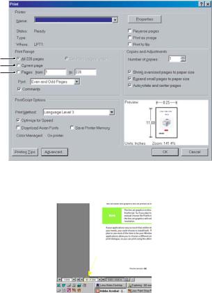
The whole manual, individual pages, or sections may be printed. The procedure is:
1.From the toolbar, select File, then Print (or press the Ctrl + P keys).
2.Choose which pages you wish to print:
(a)All pages, (1), for the entire manual.
(b)Current page, (2), for the page at which you are looking.
1
2
3
(c)Pages from and to, (3), for the range of pages you specify by entering their page numbers.
3.Click OK.
About this guide > 9
INTRODUCTION
This printer series is designed to provide highly reliable letter quality printing and high resolution graphics for the desktop/office printing environment. It combines state-of-the- art, 9-pin (ML5720/ML5721) and 24-pin (ML5790/ML5791), serial impact dot matrix printing technology with advanced materials and superior construction to provide high performance and versatility in a desktop sized unit. Careful attention to ergonomics and application needs provides user friendly operation for operators of varying technical capabilities.
FEATURES
The features include:
>OKI smart Paper HandlingTM (ML5790/ML5791)
>9-pin(ML5720/ML5721) and 24-pin(ML5790/ML5791) double arrangement operator replaceable printhead
>Direct access control panel
>Structured direct access menu for easy set up
>Printhead life: 400M characters (average) in 10 CPI Utility mode at normal 25% duty, 35% page density
>Bi-directional short-line-seeking printing
>Print speed:
ML5720/ML5721 |
ML5790/ML5791 |
||
|
|
|
|
600 |
CPS HSD (all CPIs) |
480 |
CPS HSD (10 CPI) |
|
|
|
|
700 |
CPS SSD (12 CPI only) |
576 |
CPS HSD (12 CPI) |
|
|
|
|
450 |
CPS Draft (10/12/15/20 CPI) |
360 |
CPS Draft (10 CPI) |
|
|
|
|
431 |
CPS Draft (17.1 CPI) |
540 |
CPS Draft (15 CPI) |
|
|
|
|
113 |
CPS NLQ (10/12/15 CPI) |
120 |
CPS LQ (10 CPI) |
|
|
|
|
108 |
CPS NLQ (17.1/20 CPI) |
|
|
|
|
|
|
>Paper feed
>Top/Rear/Bottom/Front path
>Rear/Front Push tractor
>Pull tractor
>Friction feed with pinch roller release
>Paper handling
>Automatic sheet loading
>Short paper tear-off available by menu selection or TEAR button operation
>Auto-loading for single sheet and continuous paper
>Auto park feature
Introduction > 10
> Paper copies
|
ML5720/ML5721 |
ML5790/ML5791 |
|
|
|
|
|
|
9 - 11 lb, 6 part (with Rear/Front |
9 - 11 lb, 6 part (See Note) |
|
|
Push feed) |
|
|
|
|
|
|
|
9 – 11 lb, 7 part (with Pull tractor |
|
|
|
Front/Bottom Pull feed) |
|
|
|
(See note) |
|
|
|
|
|
|
|
|
|
|
NOTE
Depending on the paper route and media type, printout may appear light on the last paper part. It is recommended to use High Copy mode when the print appears light.
>Paper path capability
9 - 11 lb, 6 part (with Rear/Front Push feed)
9 - 11 lb, 7 part (with Pull tractor Front/Bottom feed)
>Stationery cartridge ribbon
>Interfaces
>Standard IEEE1284 parallel interface
>USB interface
>Optional RS-232C serial interface
>Optional Network interface card
>ML5720/ML5721:Quiet operation at 55 dB(A) in quiet mode and 57 dB(A) in normal mode
>ML5790/ML5791:Quiet Operation at 52 dB(A) in quiet mode and 57 dB(A) in normal mode.
>128 kbytes max. receive buffer
>
ML5720/ML5721: Line feed resolution at 1/6 inch, 1/8 inch, n/72 inch, n/144 inch, n/216 simulated by n/288 inch
ML5790/ML5791: Line feed resolution at 1/6 inch, 1/8 inch, n/60 inch, n/72 inch, n/180 inch, n/216 inch, n/360 inch.
>Agency approved: GS,CE
>Barcode data printing
>Postnet bar code data printing
Introduction > 11

STANDARD CONFIGURATION
This printer series consists of the following components:
>Printer mechanism
>Power supply unit
>Control board (including an IEEE1284 parallel interface and USB port)
>Operator panel board
>Acoustic covers
>Tractor feed unit
OPTIONS
>RS-232C Serial Interface Board
NOTE
Ensure that the RS-232C Serial Interface board’s communication rate is up to
19.2K BPS. RS-232C with a lower K BPS cannot be used for this printer.
>LAN7120E3 100BASE-TX/10BASE-T Network Board
>Tractor unit (Push and Pull)
>Cut-sheet feeder (Single-bin only)
>Roll paper stand (ML5720/ML5790)
Introduction > 12
IDENTIFYING COMPONENT PARTS
The main parts of your printer are identified and briefly explained below.
FRONT VIEW
10 |
9 |
|
8 |
||
|
7
1 |
9 |
6
2 |
5 |
|
3 |
4
1.Power Switch: to turn the printer power ON/OFF.
2.Operator Panel: contains buttons and indicators (LEDs) (described in detail later) that allow you to operate the printer.
3.Front Feed Paper Tray: to feed the cut sheet from the front.
4.Front Cover: open to fit the front feed paper tray or to fit the tractor.
5.Platen Knob.
6.Paper Type Lever: set according to the type of paper feed - front feed (cut sheet), continuous rear feed, continuous front feed or continuous bottom pull.
7.Pull-up Guide Assembly support.
8.Top Feed Paper Tray: raise to feed cut sheet paper from the top.
9.Paper Guide: can be adjusted as required to locate the left edge of cut sheet paper.
10.Top Cover: open and close for access, for example when changing a ribbon cartridge. Keep closed for noise reduction.
Introduction > 13

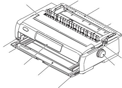
INTERNAL VIEW
11
12
13
14
11.Paper Thickness Lever: set according to the thickness of the paper.
12.Ribbon Cartridge: holds the printer ribbon.
13.Print Head: prints the character on the paper.
14.Pull-up Guide assembly: remove when using Pull tractor and optional Cut-sheet feeder.
REAR VIEW
18
19 |
17 |
16 |
15 |
20
15.USB connector: connect to USB interface cable.
16.Parallel connector: connect to parallel interface cable.
17.Optional Serial/Network connector: connect to serial or network.
18.Optional CSF/RPS connector: connect to cut-sheet feeder or roll paper stand.
19.Ventilator
20.A/C Input: connect to printer power cable.
Introduction > 14

INTERFACE SPECIFICATIONS
IEEE1284 PARALLEL INTERFACE SPECIFICATIONS
CONNECTORS AND CABLE
Connectors
Printer side:36-pin receptacle 57RE-40360-830B-D29BF (DDk Ltd.) or equivalent
Cable side:36-pin plug 57FE-30360 (DDK Ltd.) or equivalent, or 57F-36H-3R straight type with a metal hood (DDK Ltd.) or equivalent.
Cable
Use a cable less than 1.8 m in total length.
(A shielded cable is required and use of twisted-pair wires is recommended for noise prevention.)
PARALLEL INTERFACE SIGNALS
Pin No. |
Signal |
Direction |
Description |
|
|
||||||
|
|
|
|
|
|
|
|
|
Compatible |
|
Nibble |
|
|
|
|
|
|
|
|
|
|
|
|
1 |
STROBE |
To printer |
Samples input data when changing from low |
HostClk |
|||||||
|
|
|
|
|
|
|
|
|
level to high level. |
|
|
2 |
DATA BIT 1 |
To printer |
Input data: High level indicates “1” and low |
? |
|||||||
3 |
DATA BIT 2 |
|
level “0”. |
|
|
||||||
|
|
|
|
||||||||
4 |
DATA BIT 3 |
|
|
|
|
||||||
5 |
DATA BIT 4 |
|
|
|
|
||||||
6 |
DATA BIT 5 |
|
|
|
|
||||||
7 |
DATA BIT 6 |
|
|
|
|
||||||
8 |
DATA BIT 7 |
|
|
|
|
||||||
9 |
DATA BIT 8 |
|
|
|
|
||||||
|
|
|
|
|
|
|
|
|
|
|
|
10 |
ACKNOWLEDGE |
From printer |
Indicates character input completion, or func- |
PrtClk |
|||||||
|
|
|
|
|
|
|
|
|
tion operation end, at low level. |
|
|
11 |
BUSY |
From printer |
Indicates data cannot be received at high level. |
PrtBusy |
|||||||
|
|
|
|
|
|
|
|
|
Data can be input at low level. |
|
|
12 |
PAPER END |
From printer |
High level indicates paper end. |
AckDataReq |
|||||||
13 |
SELECT |
From printer |
High level indicates select (on line) condition. |
Xflag |
|||||||
|
|
|
|
|
|
|
|
|
|
||
14 |
AUTO FEED |
To printer |
When "Auto Feed" in the menu is set as |
HostBusy |
|||||||
|
|
|
|
|
|
|
|
|
valid under EPSON mode, this signal goes |
|
|
|
|
|
|
|
|
|
|
|
to the low level and the printer generates a |
|
|
|
|
|
|
|
|
|
|
|
line feed after receiving CR code. |
|
|
16, 33 |
0 V |
– |
Signal ground. |
< |
|||||||
17 |
CHASSIS GROUND |
– |
Frame ground. |
< |
|||||||
18 |
+5 V |
From printer |
+5V / 50mA ** |
|
< |
||||||
19 to 30 |
0 V |
– |
Twisted pair return (for pin No. 1 to 11) |
< |
|||||||
|
|
|
|
|
|
|
|
|
|||
31 |
INPUT-PRIME |
To printer |
When this signal goes to the low level, |
< |
|||||||
|
|
|
|
|
|
|
|
|
printer controller is initialized. The low level |
|
|
|
|
|
|
|
|
|
|
|
should be held for more than 0.5 ms. |
|
|
|
|
|
|
|
|
|
|
||||
32 |
FAULT |
From printer |
This signal goes from high to low level when |
nDataAvail |
|||||||
|
|
|
|
|
|
|
|
|
paper runs out. |
|
|
|
|
|
|
|
|
|
|
|
(Possible to indicate error and Off-Line state.) |
|
|
15, 34 |
|
– |
– |
Unused |
< |
||||||
35 |
|
– |
– |
Fixed to High (Connected to +5 V thru 3.3 KΩ) |
< |
||||||
|
|
|
|
|
|
|
|||||
36 |
SELECT-IN |
To printer |
In the EPSON mode, when menu item "Print |
IEEE1284 |
|||||||
|
|
|
|
|
|
|
|
|
Suppress Effective" is Yes, and the SELECT- |
active |
|
|
|
|
|
|
|
|
|
|
IN signal is high, the DC1/DC3 code is valid, |
|
|
|
|
|
|
|
|
|
|
|
and invalid when the signal is low. |
|
|
|
|
|
|
|
|
|
|
|
|
|
|
** When load is 50m A (more/less), volatage can drop or power can be cut off.
NOTE
Connector pin arrangement for above.
18 |
1 |
36 |
19 |
Interface specifications > 15
PARALLEL INTERFACE LEVELS
Low level: 0.0 V to + 0.8 V
High level: +2.4 V to +5.0 V
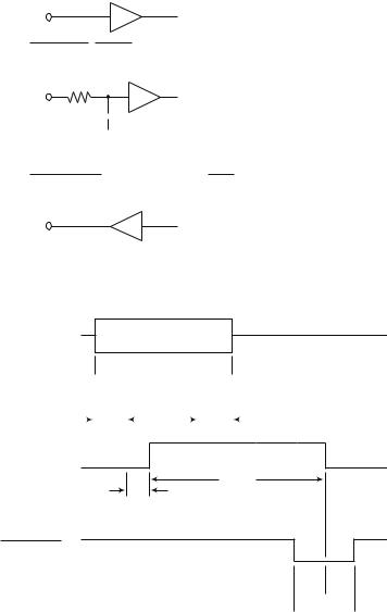
PARALLEL INTERFACE CIRCUITS
(a)Receiver
DATA BIT 1 to DATA BIT 8:
SN74LVC161284DGGR or equivalent
INPUT-PRIME, STROBE:
SN74LVC161284DGGR or equivalent
R |
|
|
C |
|
|
|
|
|
|
|
|
|
0V |
||
Signal Name |
R (Ω) |
C (pF) |
|
|
|
INPUT-PRIME |
47 |
1000 |
|
|
|
STROBE |
47 |
47 |
|
|
|
(b)Driver
ACKNOWLEDGE, PAPER END, SELECT, FAULT, BUSY SN74LVC161284DGGR or equivalent
PARALLEL INTERFACE TIMING CHART
DATA BIT1 to
DATA
DATA BIT8
|
(H) |
|
|
|
|
|
|
|
|
|
|
|
|
|
|
STROBE |
|
|
|
|
|
|
|
|
|
|
|
|
|||
|
(L) |
1 |
μs |
|
|
|
|
|
|
1 μs |
|
|
|
||
|
|
1~500 |
μs |
|
|
|
|
|
|||||||
|
|
|
|
|
|
|
|
|
|
|
|||||
|
|
|
|
min |
|
|
|
|
min |
|
|
|
|||
|
|
|
|
|
|
|
|
|
|
|
|
|
|||
(H)
BUSY
(L)
T busy
500 ns max
(H) ACKNOWLEDGE (L)
t1 t1


 t1 = 1~ 4 μs
  2~8 μs
SUPPORT MODE
>Compatible
>Nibble (PnP Device ID only)
Interface specifications > 16

UNIVERSAL SERIAL BUS (USB)
Universal Serial Bus Specification Revision 2.0 Full Speed mode compliance.
CONNECTORS
Printer Side: “B” Receptacle (Upstream Input to the USB Device)
Cable Side: Series “B” Plug
CABLE
Length: Max. 5 m (Cable must be shielded and meet the USB Spec Rev 2.0 for normal operation.)
The cable is not supplied with the printer.
USB INTERFACE SIGNALS
|
CONTACT NUMBER |
SIGNAL NAME |
|
|
|
|
|
|
1 |
Vbus |
|
|
|
|
|
|
2 |
D- |
|
|
|
|
|
|
3 |
D+ |
|
|
|
|
|
|
4 |
GND |
|
|
|
|
|
|
Shell |
Shield |
|
|
|
|
|
|
|
|
|
NOTE
Connector pin arrangement for above:
21
34
MODE AND CLASS OF DEVICE
>Full-speed driver
>Self-powered device
DATA SIGNALLING RATE
Full-speed function – 12 Mb/s
Interface specifications > 17

INTERFACE CIRCUIT
Full-speed
|
Buffer |
+ 3.3V |
|
|
|
TxD+ |
Rs |
|
|
|
|
TxD- |
Rs |
|
|
|
SIGNAL LEVEL
Input/output level
PARAMETER |
SYMBOL |
MIN. |
MAX. |
UNITS |
|
|
|
|
|
Input levels: |
|
|
|
|
|
|
|
|
|
High (driven) |
VIH |
2.0 |
|
V |
High (floating) |
VIHZ |
2.7 |
3.6 |
V |
Low |
VIL |
|
0.8 |
V |
Output levels: |
|
|
|
|
|
|
|
|
|
Low |
OL |
0.0 |
0.3 |
V |
|
|
|
|
|
High (driven) |
OH |
2.8 |
3.6 |
V |
|
|
|
|
|
Output signal crossover |
VCRS |
1.3 |
2.0 |
V |
voltage |
|
|
|
|
|
|
|
|
|
Signalling levels
Bus State |
Signalling Levels |
|||
|
|
|
|
|
Required |
|
Acceptable |
||
|
|
|||
|
|
|
||
Differential “1” |
(D+)-(D-)> 200mV and D+ > VIH(min) |
(D+)-(D-)> 200mV |
||
|
|
|
||
Differential “0” |
(D-)-(D+)> 200mV and D- > VIH(min) |
(D-)-(D+)> 200mV |
||
Single-ended 0 (SE0) |
D+ and D- < VIL(max) |
D+ and D- < VIH(min) |
||
|
|
|
|
|
Data J state: |
|
|
|
|
Low-speed |
Differential “0” |
|
|
|
Full-speed |
Differential “1” |
|
|
|
Data K state: |
|
|
|
|
Low-speed |
Differential “1” |
|
|
|
Full-speed |
Differential “0” |
|
|
|
|
|
|
|
|
Idle state: |
|
|
|
|
Low-speed |
D- > VIHZ(min) and D+ < VIL(max) |
D- > VIHZ(min) and D+ < VIH(min) |
||
Full-speed |
D+ > VIHZ(min) and D- < VIL(max) |
D+ > VIHZ(min) and D- < VIH(min) |
||
Resume state |
Data K state |
|
|
|
|
|
|
|
|
Start-of- |
Data lines switch from Idle to K state |
|
|
|
Packet (SOP) |
|
|
|
|
|
|
|
|
|
End-of-Packet (EOP) |
SE0 for ≥ 1 bit time1 followed by a J |
SE0 for ≥ 1 bit time1 followed by a J |
||
|
state for 1 bit time |
state |
||
|
|
|
|
|
Disconnect |
SE0 for ≥ 2.5μs |
|
|
|
(at downstream port) |
|
|
|
|
|
|
|
|
|
Connect |
Idle for ≥ 2ms |
Idle for ≥ 2.5μs |
||
(at downstream port) |
|
|
|
|
|
|
|
||
Reset |
D+ and D- < VIL (max) for ≥ 10ms |
D+ and D- < VIL (max) for ≥ 2.5μs |
||
NOTE
The width of EOP is defined in bit times relative to the device type receiving the EOP. The bit time is approximate.
Interface specifications > 18

TIMING CHART
Packet voltage levels
VOH(min)
VIH(min)
VIL(max)
VOL(max)
VSS |
|
|
|
|
|
|
|
Bus Driven to |
|
||
Bus Idle |
|
|
|
Last Bit |
|||||||
|
|
|
|
First Bit |
J State at end |
||||||
|
|
|
|
of Packet SE0 |
|||||||
|
SOP of Packet |
|
|
Portion |
of EOP |
||||||
|
|
|
|
|
|
|
of EOP |
|
Bus Floats |
||
|
|
|
|
|
|
|
|
|
|
Bus Idle |
|
|
|
|
|
|
|
|
|
|
|
||
VOH(min)
VIH(min)
VIL(max)
VOL(max)
VSS
Disconnect detection
D+/D- |
|
VIHZ(min) |
|
VIL |
|
D-/D+ |
|
VSS |
|
|
>2.5μs |
Device |
Disconnect |
Connected |
|
|
Detected |
Full-speed device connect detection
|
D+ |
VIH |
|
D-/D+ |
D- |
|
|
VSS |
|
|
>2.5μs |
Device |
Connect |
Connected |
Detected |
Differential data jitter
TPERIOD 

|
|
Crossover |
|
|
|
|
Differential |
|
Points |
|
|
|
|
|
|
|
|
|
|
|
Data Lines |
|
|
|
|
|
|
(VCRS) |
|
|
|
|
|
|
|
|
Consecutive |
|
|
|
|
|
|
Transitions |
|
|
TPERIOD = 12Mbps(–0.25%) |
|
|
|
N* TPERIOD + TxDJ1 |
|
|
|
TxDJ1 = Min-3.5ns~Max3.5ns |
|
|
Paired |
|
TxDJ2 = Min-4ns~Max4ns |
||
|
|
|
|
|||
|
|
Transitions |
|
|
||
|
|
N* TPERIOD + TxDJ2 |
|
|
||
|
|
|
|
|
|
|
Differential-to-EOP transition skew and EOP width
|
|
|
|
|
|
|
|
|
|
|
Crossover Point |
|||
TPERIOD |
|
|
|
|
|
|
|
|
|
|
|
|
Extended |
|
|
|
|
|
|
|
|
|
|||||||
|
Crossover |
Differential |
Points |
|
|
Data Lines |
|
|
Diff. Data-to- |
|
SE0 Skew |
|
N* TPERIOD + TxDEOP |
TxDEOP = -2ns~5ns
Source EOP Width : TFEOPT(160ns~175ns)
Receiver EOP Width : TFEOPT(80ns~)
Interface specifications > 19

Receive jitter tolerance
TPERIOD 

Differential
Data Lines
TxJR |
TxJR1 |
TxJR2 |
Consecutive
Transitions
N* TPERIOD + TxJR1
TxJR1 = Min-18.5ns~Max18.5ns
Paired TxJR2 = Min-9ns~Max9ns
Transitions
N* TPERIOD + TxJR2
Interface specifications > 20
OPTION INTERFACE SPECIFICATIONS
GENERAL SPECIFICATIONS
ITEM |
DESCRIPTION |
|
|
Interface system |
RS232C |
|
|
Data input |
Serial Input (Start-Stop synchronisation) |
|
|
Baud rate |
300, 600, 1200, 2400, 4800, 9600, 19200 BPS |
|
|
Data word length |
7 bits or 8 bits |
|
|
Parity |
Odd, even, or no parity1 |
Stop bit length |
1 bit, 2bit or more |
|
|
Message buffer length |
Buffer size is selected by ‘Receive Buffer Size’ in MENU. |
|
|
Communication protocol |
Ready/Busy |
|
X-ON/X-OFF |
|
Ready/Busy & X-ON/X-OFF (ML5720/ML5721) |
|
|
1. Setting the data length to 7 bits with no parity is not recommended.
Interface specifications > 21

INTERFACE SIGNALS
PIN NO. |
SIGNAL |
CODE |
SIGNAL |
|
FUNCTION |
|
|
|
|
|
|
1 |
Protective |
PG |
— |
|
Frame ground |
|
Ground |
|
|
|
|
|
|
|
|
|
|
2 |
Transmitted |
TD |
From |
|
Data from printer |
|
Data |
|
printer |
|
|
|
|
|
|
|
|
3 |
Received Data |
RD |
To printer |
|
Data to printer |
|
|
|
|
|
|
4 (Note 2) |
Request to Send |
RTS |
From |
|
Signal to indicate printer cannot |
|
|
|
printer |
|
receive data in printer Busy/Ready |
|
|
|
|
|
protocol |
|
|
|
|
|
|
6 (Note 3) |
Data Set Ready |
DSR |
To printer |
|
Indicates that data can be sent |
|
|
|
|
|
(Printer receives data after |
|
|
|
|
|
confirming this signal as a SPACE.) |
|
|
|
|
|
|
7 |
Signal Ground |
SG |
— |
|
Signal ground |
|
|
|
|
|
|
11 (Note 2) |
Supervisory |
SSD |
From |
|
Signal to indicate printer cannot |
|
Send Data |
|
printer |
|
receive data in printer Busy/Ready |
|
|
|
|
|
protocol |
|
|
|
|
|
|
20 (Note 2) |
Data Terminal |
DTR |
From |
|
Signal to indicate printer cannot |
|
Ready |
|
printer |
|
receive data in printer Busy/Ready |
|
|
|
|
|
protocol |
|
|
|
|
|
|
5, 8 to 10, |
— |
— |
— |
|
Unused |
12 to 19, |
|
|
|
|
|
21 to 25 |
|
|
|
|
|
|
|
|
|
|
|
|
|
|
|
|
|
NOTE |
|
|
|
|
|
1. Connector pin arrangement for above: |
|
|
|||
|
13 |
|
1 |
|
|
|
25 |
|
14 |
(Viewed from interface cable side) |
|
|
|
|
|
||
2.SSD signal output can be selected from pins 4, 11, 20 by the MENU.
3.DSR signal valid/invalid can be set by the MENU.
ELECTRICAL CHARACTERISTICS
Signal levels
RS-232C interface signal levels are as specified below, and meet the EIA Standard RS232C:
–15 to –3 V: MARK = OFF |
= LOGIC “1” |
+15 to +3 V: SPACE = ON |
= LOGIC “0” |
Interface specifications > 22

Line driver
Equivalent to HIN202
+5V 400kΩ
INPUT  OUTPUT
OUTPUT |
|
|
|
+10V |
|
|
|
|
+5V |
|
|
|
-5V
-10V
NOTE
The above figures are the standard values for a load of 3 Kohm, 15 pF.
Line receiver
Equivalent to HIN202
INPUT 
 OUTPUT
5kΩ
+30V
+3V
|
|
|
|
-3V |
|
|
|
||
INPUT |
|
|
|
-30V |
NOTE
If the power on the input side is OFF, the output of the receiver becomes high (+2.4 V or more) at TTL level.
Interface specifications > 23

INTERFACE TIMING CHARTS
Receiving timing chart
DSR signal
SPACE
MARK
Start bit
Stop bit
SPACE
RD
MARK
0.5 bit
More than 0 μs |
More than 300 μs |
NOTE
DSR signal valid/invalid can be set by the Menu.
SSD signal timing chart
|
|
|
|
Data |
|||||||
RD |
|
|
|
|
|
Stop bit |
|||||
|
|
|
|
|
|
|
|
||||
SPACE |
|
|
|
|
|
|
|
|
|
|
|
MARK |
|
|
|
|
|
|
|
|
|
|
|
|
Start bit |
|
|
|
0.5 bit |
||||||
|
|
|
|
|
|
||||||
|
|
|
|
|
|||||||
|
|
|
|
|
|
|
|
|
|
|
|
|
|
|
|
|
|
|
MAX 5 ms |
||||
DTR |
|
|
|
|
|
|
|
|
|||
|
|
|
|
|
|
|
|
||||
BUSY |
|
|
|
|
|
|
|
|
|||
|
|
|
|
|
|
|
|
||||
READY |
|
|
|
|
|
|
|
|
|
|
|
|
|
|
|
|
|
|
|
|
|||
RECEIVING MARGIN
Receiving margin is more than 37% at any baud rate.
DESCRIPTION OF COMMUNICATION PROCEDURES
The types of protocol can be selected by menu communication procedures: READY/BUSY, X-ON/X-OFF and READY/BUSY & X-ON/X-OFF (ML5720/ML5721).
INTERFACE CONTROL CODE
The following function codes are used in the high-speed serial interface:
|
COMMAND |
CODE |
|
|
|
|
|
|
DC1 |
(17)D (11)H |
|
|
|
|
|
|
DC3 |
(19)D (13)H |
|
|
|
|
|
|
|
|
|
NOTE
Characters to be printed according to the parity error indication code (40)H will differ depending on the setting of the printer character set. Refer to the printer User’s Guide.
Interface specifications > 24

Ready/Busy protocol
|
Block format |
|
|
Free |
|
|
|
|
|
|||
|
|
|
|
|
|
|
|
|
|
|
|
|
|
Error indication |
|
The parity error indication is printed as |
|||||||||
|
|
|
|
character 40(H). |
|
|
||||||
|
|
|
|
|
|
|
|
|
|
|
|
|
|
Busy state indication |
The busy signal turns on (becomes Busy) |
||||||||||
|
|
|
|
when the space in the interface buffer has |
||||||||
|
|
|
|
become less than 256 bytes. The busy signal |
||||||||
|
|
|
|
turns off (becomes Ready) after 200 ms or 1 |
||||||||
|
|
|
|
second has passed if 256 bytes have |
||||||||
|
|
|
|
recovered within 200 ms or 1 second. If the |
||||||||
|
|
|
|
recovery time exceeds 200 ms or 1 second, |
||||||||
|
|
|
|
the busy signal turns off (becomes Ready) |
||||||||
|
|
|
|
immediately after the recovery has occurred. |
||||||||
|
|
|
|
|
|
|
|
|
|
|
|
|
Timing chart |
|
|
|
|
|
|
|
|
|
|
|
|
|
|
|
|
|
|
|
|
|
|
|
|
|
|
RD |
|
|
DATA 1 |
|
|
|
DATA 2 |
||||
|
Threshold of the |
8K |
|
|
|
|
|
|
|
|
|
|
|
|
|
|
|
|
|
|
|
|
|
||
|
|
|
|
|
|
|
|
|
|
|
||
|
|
|
|
|
|
|
|
|
|
|
|
|
|
characters in |
512 |
|
|
|
|
|
|
|
|
|
|
|
|
|
|
|
|
|
|
|
|
|
||
|
the buffer |
|
|
|
|
|
|
|
|
|
|
|
|
|
0 |
|
|
|
|
|
|
|
|
|
|
|
DTR |
ON (BUSY) |
|
|
|
|
|
|
|
|
||
|
|
|
|
|
|
|
|
|
|
|||
|
|
|
|
|
|
|
|
|
|
|||
|
|
|
OFF (READY |
|
|
200 ms or 1 second minimum |
|
|
|
|||
|
|
|
|
|
|
|
||||||
|
|
|
|
|
|
|
|
|
|
|
||
|
|
|
|
|
|
|
|
|
|
|
|
|
X-ON/X-OFF protocol
Block format |
Free |
|
|
Error indication |
The parity error indication character is |
|
converted into code 40(H). |
|
|
Busy state indication |
The DC3 will be sent to the transmission side |
|
immediately after the space in the interface |
|
buffer has become less than 256 bytes to |
|
indicate that receiving is impossible. The |
|
transmission of the DC3 stops when data |
|
receiving has stopped. If the recovery time |
|
for 256 bytes is within 200 ms or 1 second |
|
after the DC3 is sent, DC1 will be sent 200 |
|
ms or 1 second after the recovery to indicate |
|
that receiving is possible. If the recovery |
|
time exceeds 200 ms or 1 second, the DC1 |
|
is sent immediately after the recovery has |
|
occurred. |
|
|
Timing chart
RD
TD |
PRINTING |
ON
BUSY state
OFF
|
256 characters or less |
|
|
|
|||||
|
|
|
|
|
|
|
Waiting for BUSY |
|
|
|
|
|
|
|
|
|
|
|
|
|
|
|
|
|
|
|
|
|
|
DATA 1 |
|
|
|
|
|
|
DATA |
||
|
|
|
|
|
state to be free |
|
|||
|
|
|
|
|
|
|
|
|
|
3 |
3 |
3 |
|
|
|
1 |
|
||
- |
- |
- |
|
|
|
|
|||
|
C |
C |
C |
|
C |
||||
|
D |
D |
D |
|
D |
||||
200 ms or 1 second minimum
NOTE
If data is transferred when the printer is still BUSY, the printer sends a DC3 code every time it receives data.
Interface specifications > 25
LOCAL TEST FUNCTION
Circuit Test mode setting
Diagnostic: Test set by menu
Test connector: Connect the test connectors as shown below to the interface connectors.
|
|
2 |
|
|
TD |
|
|
|
3 |
||
|
|
||
|
RD |
|
|
|
4 |
||
|
|
||
|
RTS |
|
|
|
5 |
||
|
|
||
Equivalent to Cannon DB-25P |
CTS |
|
|
8 |
|||
|
|
||
|
CD |
|
|
|
11 |
||
|
|
||
|
SSD |
|
|
|
20 |
||
|
|
||
|
DTR |
|
|
|
6 |
||
|
|
||
|
DSR |
|
|
|
|
||
|
|
|
Circuit Test mode function
After the settings outlined in Circuit Test mode setting are completed and power is turned on, the serial interface checks the message buffer memory and interface driver and receiver circuits, then prints all characters. To start and stop this test, press the SEL button on the front of the printer. Details of this test are explained below.
1.Print the program revision with two numerical characters.
2.Print “LOOP TEST.”
3.Check memory for message buffer.
Print “GOOD” if memory check is OK, and print “BAD” if memory check fails.
4.Output LOW to DTR, RTS, and SSD signals. If a CTS, DSR, or CD signal is HIGH, print “BAD”. If the CTS, DSR, and CD signals are all LOW, print “IF GOOD”.
Output HIGH to DTR, RTS, and SSD signals. If a CTS, DSR, or CD signal is LOW, print “IF BAD.” If the CTS, DSR and CD signals are all HIGH, print “IF GOOD.”
5.Transmit characters from code 20H to 7FH by TD signals. At the same time, characters are received from the RD signal and stored in the message buffer.
6.Print the characters that were stored in the message buffer as indicated in Step 5.
7.Repeat from Step 1.
Interface specifications > 26
OPERATOR INTERFACE
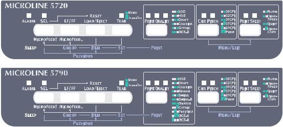
OPERATOR PANEL FUNCTIONS
The operator panel buttons and LEDs are located as follows:
Button functions depend on the printer state which can be any one of:
>Print Mode (for a summary of print modes and features see “Appendix B – Print modes/features” on page 311.)
>Hex Dump Mode
>Menu Mode
>Test Mode
>Power On Mode
>Limited Operation
Operator interface > 27
PRINT MODE
BUTTON |
STATUS |
FUNCTION |
|
|
|
SEL |
On-line |
Sets the printer to off-line. |
|
|
|
|
Off-line |
Sets the printer to on-line. |
|
|
|
LF/FF |
On-line/Off-line |
Feeds paper by one line. |
|
|
When pressed for more than 500ms, |
|
|
performs form feed. |
|
|
|
LOAD/EJECT |
On-line/Off-line |
|
|
When no paper is loaded |
Performs paper feed. |
|
When paper is loaded: |
|
|
Continuous forms |
Retracts the form to the Pin Tractor. |
|
Cut-sheet paper |
Ejects the cut sheet. |
|
Pull feed |
Ineffective. |
|
|
|
TEAR |
On-line/Off-line |
|
|
Continuous forms |
Delivers the continuous form to the cut |
|
|
position. |
|
Pull feed |
Ineffective. |
|
|
|
PRINT QUALITY |
On-line/Off-line |
Select a font. |
|
|
|
CHR. PITCH |
On-line/Off-line |
Select a character pitch. |
|
|
|
PRINT SPEED |
On-line/Off-line |
Select print speed. |
|
|
|
SEL + LF/FF |
On-line/Off-line |
Ineffective. |
|
|
|
SEL + LOAD/EJECT |
On-line |
Ineffective. |
|
|
|
|
Off-line |
Holding down the SEL button and |
|
|
pressing the LOAD/EJECT button |
|
|
initialises the new Menu settings. |
|
|
|
SEL + CHR.PITCH |
On-line |
Ineffective. |
|
|
|
|
Off-line |
Selects MENU configuration. |
|
|
|
LF/FF + LOAD/EJECT |
On-line/Off-line |
Ineffective. |
|
|
|
LOAD/EJECT + SEL |
On-line/Off-line |
|
|
ML5720/ML5721 |
Performs microfeed (forward) 1/144 inch |
|
|
when paper is loaded. |
|
|
|
|
ML5790/ML5791 |
Performs microfeed (forward) 1/180 inch |
|
|
when paper is loaded. |
|
|
|
LOAD/EJECT + LF/FF |
On-line/Off-line |
|
|
ML5720/ML5721 |
Performs microfeed (reverse) 1/144 inch |
|
|
when paper is loaded. |
|
|
|
|
ML5790/ML5791 |
Performs microfeed (reverse) 1/180 inch |
|
|
when paper is loaded. |
|
|
|
TEAR + SEL |
On-line/Off-line |
|
|
ML5720/ML5721 |
Performs microfeed (forward) 1/144 inch |
|
|
when paper is in tear off position. |
|
|
|
|
ML5790/ML5791 |
Performs microfeed (forward) 1/180 inch |
|
|
when paper is in tear off position. |
|
|
|
Operator interface > 28
BUTTON |
STATUS |
FUNCTION |
|
|
|
TEAR + LF/FF |
On-line/Off-line |
|
|
ML5720/ML5721 |
Performs microfeed (reverse) 1/144 inch |
|
|
when paper is in tear off position. |
|
|
|
|
ML5790/ML5791 |
Performs microfeed (reverse) 1/180 inch |
|
|
when paper is in tear off position. |
|
|
|
PRINT QUALITY + SEL |
On-line/Off-line |
|
|
ML5720/ML5721 |
Performs microfeed (reverse) 1/144 inch |
|
|
when paper is in Top of Form position. |
|
|
|
|
ML5790/ML5791 |
Performs microfeed (reverse) 1/180 inch |
|
|
when paper is in Top of Form position. |
|
|
|
PRINT QUALITY + LF/ |
On-line/Off-line |
|
FF |
ML5720/ML5721 |
Performs microfeed (forward) 1/144 inch |
|
||
|
|
when paper is in Top of Form position. |
|
|
|
|
ML5790/ML5791 |
Performs microfeed (forward) 1/180 inch |
|
|
when paper is in Top of Form position. |
|
|
|
CHR.PITCH + PRINT |
On-line/Off-line |
Enters menu mode. |
SPEED |
|
|
|
|
|
Operator interface > 29

HEX DUMP MODE, MENU MODE, TEST MODE
BUTTON |
HEX DUMP MODE |
MENU MODE |
TEST MODE |
||
|
|
|
|
||
SEL |
On-line: Sets printer Off- |
- |
Temporarily suspends |
||
|
line. |
|
|
test printing. |
|
|
Off-line: Sets printer On- |
|
|
||
|
line. |
|
|
|
|
|
|
|
|
||
LF/FF |
On-line: Feeds paper by |
Increments a group in a |
|
||
|
one line. |
‘GROUP’. |
|
||
|
When pressed for more |
|
|
||
|
than 400ms, performs form |
|
|
||
|
feed. |
|
|
|
|
|
Off-line: When paper is |
|
|
||
|
loaded, performs form feed |
|
|
||
|
for continuous forms and |
|
|
||
|
ejects cut-sheet paper. |
|
|
||
|
|
|
|
||
LOAD/EJECT |
> When no paper is loaded: |
Increments an item in |
|
||
|
|
Performs paper feed. |
an ‘ITEM’. |
|
|
|
> When paper is loaded: |
|
|
||
|
|
> |
Continuous |
|
|
|
|
|
forms:Retracts the |
|
|
|
|
|
form to the Pin |
|
|
|
|
Tractor. |
|
|
|
|
|
> Cut-sheet paper: |
|
|
|
|
|
|
Ejects the cut sheet. |
|
|
|
|
> |
Pull feed: Ineffective. |
|
|
|
|
|
|
|
|
TEAR |
> |
Delivers the continuous |
Increments a set in a |
|
|
|
|
form to the cut position. |
‘SET’. |
|
|
|
> |
Pull Feed: Ineffective. |
|
|
|
|
|
|
|
|
|
|
|
|
|
Selects Print Quality |
|
QUALITY |
|
|
|
|
|
|
|
|
|
|
|
CHR. PITCH |
|
|
|
|
Selects Character Pitch |
|
|
|
|
|
|
PRINT SPEED |
|
|
|
|
Selects Print Speed. |
|
|
|
|
|
|
SEL + LF/FF |
|
|
|
Decrements a group in |
|
|
|
|
|
a ‘Group’. |
|
|
|
|
|
|
|
SEL + LOAD/ |
|
|
|
Decrements an item in |
|
EJECT |
|
|
|
an ‘ITEM’. |
|
|
|
|
|
|
|
SEL + TEAR |
|
|
|
Decrements a set in a |
|
|
|
|
|
‘SET’. |
|
|
|
|
|
|
|
CHR. PITCH + |
|
|
|
Exits Menu mode. |
|
PRINT SPEED |
|
|
|
|
|
|
|
|
|
|
|
Operator interface > 30
Loading...