


Push Tractor
Installation Instructions:
ML620, ML621, ML690, ML691
Pull Tractor 1 Tracteur ou le propulseur 3 Mecanismo de tracción de arrastre 5 Tracionador de puxar 7
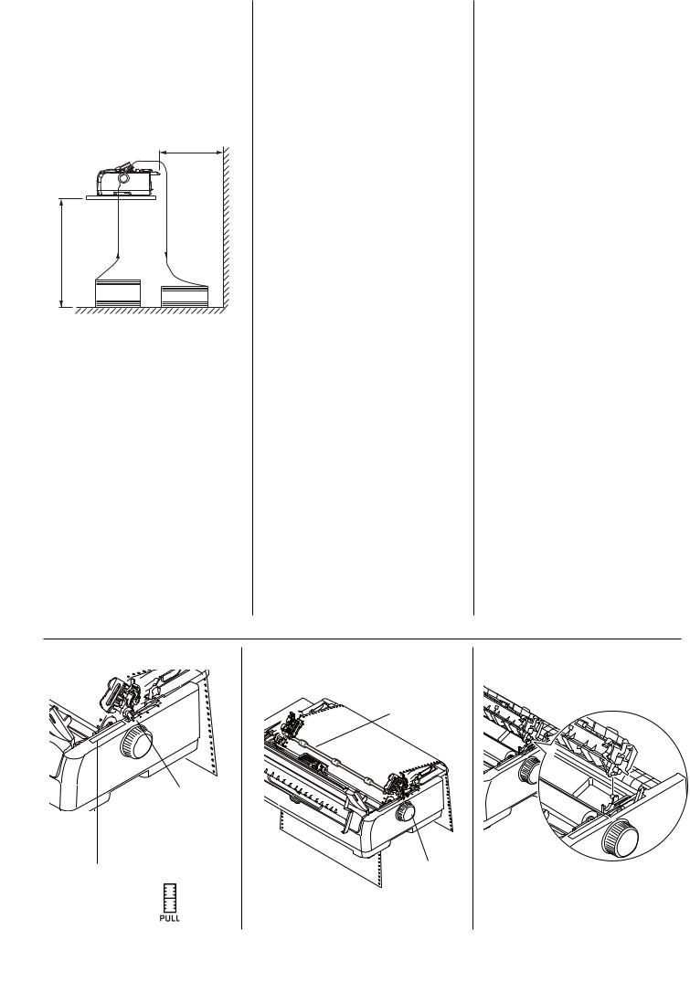
Use the pull tractor to efficiently feed multi part forms, labels, etc., in a straight path through the bottom of the printer.
Prepare the Printer
1.Turn the printer OFF.
2.Open the access cover (Fig. 1) and center the printhead.
CAUTION! The printhead may be hot!
NOTE: The grooves on the back side of the Pull Tractor (as described in the following step number 2; one on the far left;
one on the far right; Fig. 2) attach to the same two pins as the Pull-up Roller Assembly.
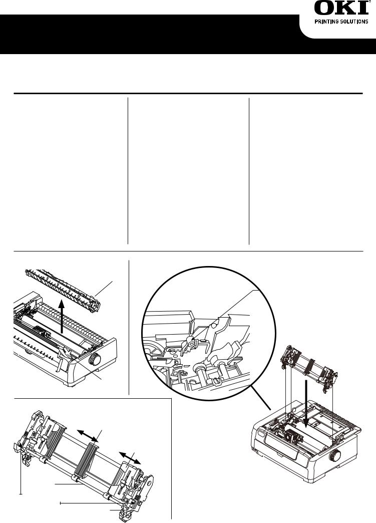
Install the Tractor
1.Remove the Pull-up Roller Assembly (Fig. 1). Rotate the assembly towards the back of the printer and pull it up off the left and right side pins to remove it. Store the assembly for future use.
2.Install the Pull Tractor. Find the grooves (Fig. 2) on the back side of the tractor (the front side of the tractor has the sprocket pins and tractor covers). With the front side of the tractor facing the front of the printer, use your fingers to help guide the grooves (Fig. 3) onto the pins on the printer, and push the tractor down until it clicks into place.
Figure 1 |
PULL-UP |
Figure 3 |
|
ROLLER |
|
|
ASSEMBLY |
|
PULL
TRACTOR
|
ACCESS |
|
|
COVER |
|
Figure 2 |
|
|
|
|
TRACTOR |
|
PAPER |
PINS and |
|
GUIDE |
TRACTOR |
|
|
COVER |
|
|
(SLIDES |
|
|
WHEN NOT |
|
|
LOCKED) |
BAIL |
|
|
ARM |
|
|
TRACTOR |
|
|
GROOVES |
|
|
(ON BACK |
LOCK |
|
SIDE OF |
|
|
LEVER |
|
|
TRACTOR) |
|
|
|
|
|
|
|
1 / English |
Load Paper
1.Make sure the Paper Type lever (Fig. 4) is in the PULL position.
2.Place the printer on a slotted printer stand, carefully aligning the slot in the stand with the slot in the base of the printer.
3.Adjust the Paper Thickness Lever to suit the paper.
4.Pull open the tractor bail arm (Fig. 2), place the paper through the slot in the base of the printer and bring the paper through the slot.
5.Lift the lock lever (Fig. 2) of the left Pin Tractor and slide the Pin Tractor as required to adjust the paper position. Then press the lock lever back down to lock the Pin Tractor.
6.Lift the lock lever of the right pin tractor and slide the
Pin Tractor to the required position to accommodate
the width of the continuous forms to be used. Move the paper guide to midway between the left and right Pin Tractors.
7.Raise the bail arm (Fig. 2), open the left and right Pin Tractor covers and feed the continuous forms in the direction of the arrow,
loading the sprocket holes in the forms onto the sprocket pins.
NOTE: Make sure that paper is fed straight into the printer to avoid the possibility of skew printing, irregular line feeding and paper jams.
8.Make sure that the forms are properly aligned on the sprocket pins, then close the Pin Tractor covers. Adjust the right Pin Tractor to accommodate the width of the continuous forms, taking care that the forms are held neither too loosely nor too tightly between the Pin Tractors. Press the lock lever down to lock the right Pin Tractor in the desired position. Swing the bail arm down and push to lock it in place (Fig. 5).
NOTE: Make sure that the continuous form is pulled down to take up slack. Slack will cause the line spacing to be inconsistent. Turn the platen to help remove the slack.
9. Close the access cover.
10.Use the platen knob (Fig. 5) to adjust or set the TOF.
11.Turn the printer ON.
NOTE: If the TOF position shifts because of taking up slack, press the LF/FF key to set the TOF position. Do not use the platen knob for this option as this will cause irregular line spacing.
Removing the Pull
Tractor
1.Turn the printer OFF.
2.Remove paper from the printer using the platen knob (Fig. 5).
3.Open the access cover and center the printhead.
CAUTION! The printhead may be hot!
4.Release the pull tractor by squeezing the silver lock tabs at the base of the tractor while rotating the tractor to the rear of the printer. Lift the tractor off.
5.Position the Pull-up Assembly (Fig. 1) over the platen and line up the grooves on the assembly with the pins beside the gray tabs (Fig. 6). Push the assembly onto the pins and
pull the assembly toward the front of the printer until it clicks into place.
Figure 4 |
Figure 5 |
Figure 6 |
BAIL
ARM
|
SET PAPER |
|
|
TYPE LEVER |
|
|
FOR PULL |
|
|
FEED |
|
GUIDE ON |
PLATEN |
ALIGN PULL-UP |
PRINTER SHOWS |
KNOB |
|
POSITIONS |
|
ROLLER GROOVES |
FOR EACH FEED |
|
WITH PRINTER PINS |
METHOD (I.E., |
|
|
PAPER TYPE) |
|
|
2 / English
Directives d’installation
Tracteur ou le propulseur ML620, ML621, ML690, ML691
Utilisez tracteur ou le propulseur pour efficacement alimenter des formulaires à exemplaires multiples, des étiquettes, etc. en suivant un circuit papier en ligne droite par le fond de l’imprimante.
Préparation de l’imprimante
1.Éteignez l’imprimante.
2.Ouvrez le capot d’accès (Fig. 1) et centrez la tête d’impression.
ATTENTION! La tête d’impression peut être BRÛLANTE!
REMARQUE : Les rainures
àl’arrière du tracteur ou le propulseur (comme décrit à l’étape 2 ci-dessous; une à l’extrême gauche et l’autre
àl’extrême droite; Fig. 2) se fixent sur les mêmes broches que l’assemblage de rouleau de traction.
Installation du tracteur
1.Enlevez l’assemblage de rouleau de traction (Fig. 1). Faites tourner l’assemblage vers l’arrière de l’imprimante et soulevez-le des broches à gauche et à droite
pour l’enlever. Rangez l’assemblage pour utilisation ultérieure.
2.Installez le tracteur. Trouvez les rainures (Fig. 2) à l’arrière du tracteur (les pignons et les couvercles de pignon sont à l’avant
du tracteur). Avec l’avant du tracteur orienté vers l’avant de l’imprimante, utilisez vos doigts pour vous aider à guider les rainures (Fig. 3) sur les broches de l’imprimante et poussez sur le tracteur jusqu’à ce qu’il s’enclenche.
Figure 1 |
L’ASSEMBLAGE |
Figure 3 |
|
DE ROULEAU DE |
|
|
TRACTION |
|
TRACTEUR
OU LE
PROPULSEUR
|
CAPOT |
|
|
D’ACCÈS |
|
Figure 2 |
|
|
|
LE GUIDE |
TRACTEUR ET |
|
COUVERCLE |
|
|
PAPIER |
|
|
DE TRACTEUR |
|
|
|
|
|
|
(COULISSENT |
|
|
SI PAS |
|
|
VERROUILLÉS) |
BRAS DU |
|
|
PRESSE- |
|
|
PAPIER |
|
|
RAINURES |
|
|
DE TRACTEUR |
LEVIER DE |
|
(AU DOS DU |
|
|
TRACTEUR) |
VERROUILLAGE |
|
|
|
3 / Français |
 Loading...