


XTrail T30 2005
Table of contents
 Loading...
EM-1
ENGINE MECHANICAL
B ENGINE
CONTENTS
C
D
E
F
G
H
I
J
K
L
M
SECTION EM
A
EM
Revision: 2005 March 2005 X-Trail
ENGINE MECHANICAL
PRECAUTIONS .......................................................... 3
Precauti ons for Drain Engine Cool ant an d Engi ne
Oil ............................. ................................................ 3
Precautions for Disconnecting Fuel Piping .............. 3
Precautions for Removal and Disassembly ............. 3
Precautions for Inspection, Repair and Replace-
ment ......................................................................... 3
Precautions for Assembly and Installation ............... 3
Precautions for Angle Tightening ............................. 3
Precautions for Liquid Gasket .................................. 4
REMOVAL OF LIQUID GASKET .......................... 4
LIQUID GASKET APPLICATION PROCEDURE ..... 4
PREPARATION .............................. .................... ......... 5
Special Service Tools ............................................... 5
Commercial Service Tools ........................................ 6
NOISE, VIBRATION AND HARSHNESS (NVH)
TROUBLESHOOTING .......................... ...................... 9
NVH Troubleshooting — Engine Noise .................... 9
Use the Chart Below to Help You Find the Cause
of the Symptom. ................................. ...... ....... ....... 10
DRIVE BELTS ............................................................11
Checking Drive Belt .................................................11
Tension Adjustment .................................................11
Removal and Installation .........................................11
REMOVAL ............................................................11
INSTALLATION ................................................... 12
Removal and Installation of Drive Belt Auto-Ten-
sioner ..................................................................... 12
REMOVAL ........................................................... 12
INSTALLATION ................................................... 13
AIR CLEANER AND AIR DUCT ............................... 14
Removal and Installation ........................................ 14
REMOVAL ........................................................... 14
INSPECTION AFTER REMOVAL ....................... 15
INSTALLATION ................................................... 15
Changing Air Cleaner Filter ......... ....... ...... .............. 15
REMOVAL ........................................................... 15
INSTALLATION ................................................... 15
INTAKE MANIFOLD ................................................. 16
Removal and Installation ........................................ 16
REMOVAL ........................................................... 16
INSPECTION AFTER REMOVAL ....................... 18
INSTALLATION ................................................... 18
INSPECTION AFTER INSTALLATION ................ 19
EXHAUST MANIFOLD AND THREE WAY CATA-
LYST ........... ................................. .......................... .... 20
Removal and Installation ........................................ 20
REMOVAL ........................................................... 20
INSPECTION AFTER REMOVAL ....................... 21
INSTALLATION ................................................... 21
OIL PAN AND OIL STRAINER ................................. 22
Removal and Installation ........................................ 22
REMOVAL ........................................................... 22
INSPECTION AFTER REMOVAL ....................... 24
INSTALLATION ................................................... 24
INSPECTION AFTER INSTALLATION ................ 26
IGNITION COIL ........................................ ...... ....... .... 27
Removal and Installation ........................................ 27
REMOVAL ........................................................... 27
INSTALLATION ................................................... 27
SPARK PLUG (PLATINUM-TIPPED TYPE) .............28
Removal and Installation ........................................ 28
REMOVAL ........................................................... 28
INSPECTION AFTER REMOVAL ....................... 28
INSTALLATION ................................................... 29
FUEL INJECTOR AND FUEL TUBE ........................30
Removal and Installation ........................................ 30
REMOVAL ........................................................... 30
INSTALLATION ................................................... 32
INSPECTION AFTER INSTALLATION ................ 34
ROCKER COVER .....................................................35
Removal and Installation ........................................ 35
REMOVAL ........................................................... 35
INSTALLATION ................................................... 36
CAMSHAFT ..............................................................37
Removal and Installation ........................................ 37
REMOVAL ........................................................... 37
INSPECTION AFTER REMOVAL ....................... 40

EM-2
Revision: 2005 March 2005 X-Trail
INSTALLATION ................................ ............. ....... 42
INSPECTION AFTER INSTALLATION ................45
Valve Clearance ......................................................46
INSPECTION ............................ ............. ..............46
ADJUSTMENT ....................................................47
TIMING CHAIN .......................................................... 49
Removal and Installation ........................................49
REMOVAL ...........................................................49
INSPECTION AFTER REMOVAL ........................53
INSTALLATION ................................ ............. ....... 54
INSPECTION AFTER INSTALLATION ................58
OIL SEAL ..................................................................59
Removal and Installation of Valve Oil Seal .............59
REMOVAL ...........................................................59
INSTALLATION ................................ ............. ....... 59
Removal and Installation of Front Oil Seal .............60
REMOVAL ...........................................................60
INSTALLATION ................................ ............. ....... 60
Removal and Installation of Rear Oil Seal ..............61
REMOVAL ...........................................................61
INSTALLATION ................................ ............. ....... 61
CYLINDER HEAD ..................................................... 62
On-Vehicle Service .................................................62
CHECKING COMPRESSION PRESSURE .........62
Removal and Installation ........................................63
REMOVAL ...........................................................63
INSPECTION AFTER REMOVAL ........................64
INSTALLATION ................................ ............. ....... 65
INSPECTION AFTER INSTALLATION ................65
Disassembly and Assembly .................................... 67
DISASSEMBLY ................................................... 67
ASSEMBLY ......................................................... 68
Inspection After Disassembly .................................69
VALVE DIMENSIONS ............................ ....... .......69
VALVE GUIDE CLEARANCE ................ ....... .......70
VALVE GUIDE REPLACEMENT ........... ....... .......70
VALVE SEAT CONTACT ....................... ..............72
VALVE SEAT REPLACE ME NT ...........................72
VALVE SPRING SQUARENESS .........................73
VALVE SPRING DIMENSIONS AND VALVE
SPRING PRESSURE LOAD .... ....... ...... ....... .......73
ENGINE ASSEMBLY ................................................74
Removal and Installation (2WD Models) ................74
REMOVAL ...........................................................75
INSTALLATION ................................ ............. ....... 76
INSPECTION AFTER INSTALLATION ................77
Removal and Installation (AWD Models) ................78
REMOVAL ...........................................................78
INSTALLATION ................................ ............. ....... 81
INSPECTION AFTER INSTALLATION ................81
CYLINDER BLOCK ................................................... 82
Disassembly and Assembly .................................... 82
DISASSEMBLY ................................................... 83
ASSEMBLY ...................................................... ....86
How to Select Piston and Bearing ..........................91
DESCRIPTION ....................................................91
HOW TO SELECT PISTON .................................92
HOW TO SELECT CONNECTING ROD BEAR-
ING .......................................................................93
HOW TO SELECT MAIN BEARING ....................95
Inspection After Disassembly ..................................99
CRANKSHAFT END PLAY ..................................99
CONNECTING ROD SIDE CLEARANCE ...........99
PISTON TO PISTON PIN OIL CLEARANCE .......99
PISTON RING SIDE CLEARANCE ...................100
PISTON RING END GAP ..................................100
CONNECTING ROD BEND AND TORSION .....101
CONNECTING ROD BIG END DIAMETER ......101
CONNECTING ROD BUSHING OIL CLEAR-
ANCE .............................. ...................................101
CYLINDER BLOCK DISTORTION ....................102
MAIN BEARING HOUSING INNER DIAMETER .103
PISTON TO CYLINDER BORE CLEARANCE ..103
CRANKSHAFT MAIN JOURNAL DIAMETER ...104
CRANKSHAFT PIN JOURNAL DIAMETER ......105
OUT-OF-ROUND AND TAPER OF CRANK-
SHAFT ...............................................................105
CRANKSHAFT RUNOUT ..................................105
CONNECTING ROD BEARING OIL CLEAR-
ANCE .............................. ...................................105
MAIN BEARING OIL CLEARANCE ...................106
MAIN BEARING CRUSH HEIGHT ....................107
CONNECTING ROD BEARING CRUSH
HEIGHT .............................................................107
LOWER CYLINDER BLOCK MOUNTING BOLT
OUTER DIAMETER ...........................................107
CONNECTING ROD BOLT OUTER DIAMETER .107
FLYWHEEL DEFLECTION (M/T MODELS) ......108
MOVEMENT AMOUNT OF FLYWHEEL (M/T
MODELS) ........................ ...................................108
SERVICE DATA AND SPECIFICATIONS (SDS) ....109
Standard and Limit ................................................109
GENERAL SPECIFICATIONS ...........................109
DRIVE BELT ......................................................109
INTAKE MANIFOLD AND EXHAUST MANI-
FOLD .................................................................109
SPARK PLUG .................................................. ..109
CYLINDER HEAD ........................ ....... ...... ....... ..109
VALVE .................................... ............................110
CAMSHAFT AND CAMSHAFT BEARING ....... ..114
CYLINDER BLOCK ................ ............................114
PISTON, PISTON RING AND PISTON PIN ......116
CONNECTING ROD ..........................................117
CRANKSHAFT ....................... ...... ....... ...... ....... ..117
MAIN BEARING .................................................119
CONNECTING ROD BEARING .......... ...... ....... ..120

PRECAUTIONS
EM-3
C
D
E
F
G
H
I
J
K
L
M
A
EM
Revision: 2005 March 2005 X-Trail
PRECAUTIONS PFP:00001
Precautions for Drain Engine Coolant and Engine Oil ABS00CIL
Drain engine coolant and engine oil when the engine is cooled.
Precautions for Disconnecting Fuel Piping ABS00CIM
● Before starting work, make sure no fire or spark producing items are in the work area.
● Release fuel pressure before disassemb ly.
● After disconnecting pipes, plug openings to stop fuel leakage.
Precautions for Removal and Disassembly ABS00CIN
● When instructed t o use special service tools, use the specified tools. Al ways be careful to work safely,
avoid forceful or uninstructed operations.
● Exercise maximum care to avoid damage to mating or sliding surfaces.
● Cover openings of engine system with a tape or the equivalent, if necessary, to seal out foreign materials.
● Mark and arrange disassembly parts in an organized way for easy troubleshooting and re-assembly.
● When looseni ng nu t s an d b ol t s, a s a b as ic ru le , st a r t wit h the on e fu rt he st o ut si de , the n th e on e d iag on al ly
opposite, and so on. If the order of loosening is specified, do exactly as specified. Power tools may be
used where noted in the step.
Precautions for Inspection, Repair and Replacement ABS00CIO
Before repairing or repla cing, thorou ghly inspec t parts. Inspect new repl acement parts in the s ame way, and
replace if necessary.
Precautions for Assembly an d Installation ABS00CIP
● Use torque wrench to tighten bolts or nuts to specification.
● When tightening nuts and bolts, as a basic rule, equally tighten in several different steps starting with the
ones in center, then ones on inside and outside diagonally in this order. If the order of tightening is speci-
fied, do exactly as spe ci fied.
● Replace with new gasket, packing, oil seal or O-ring.
● Thoroughly wa sh, c lean , an d air- bl ow eac h p art. Care ful ly ch eck en gin e oil o r en gine coolan t p ass ages for
any restriction and blockage.
● Avoid damaging sliding or mating surfaces. Completely remove foreign materials such as cloth lint or dust.
Before assembly , oil sliding surfaces well.
● Release air within route when refilling after draining engine coolant.
● Before starting the engine, apply fuel pressure to fuel lines with turning ignition switch “ON” (with the
engine stopped). Then make sure there are no leaks at fuel line connections.
● After repairing, start the e ngine a nd incre ase engine speed t o check engine coolant, fuel, en gine oil , and
exhaust gases for leakage.
Precautions f or Angle Tightening ABS00CIQ
● Use the angl e wren ch [SST: KV10112100 (BT8653- A)] fo r the f inal tight ening of the follo wing engine part s.
– Cylinder head bolts
– Lower cylinder block bolts
– Connecting rod cap bolts
– Crankshaft pu lley bolt (No angle wrench is required a s the bol t flange i s provided with notc hes for an gle
tightening)
– Balancer unit
● Do not use a torque value for final tigh ten in g.
● The torque value for these parts are for a preliminary step.
● Ensure thread and seat surfaces are clean and coated with engine oil.
EM-4
PRECAUTIONS
Revision: 2005 March 2005 X-Trail
Precautions for Liquid Gasket ABS00CIR
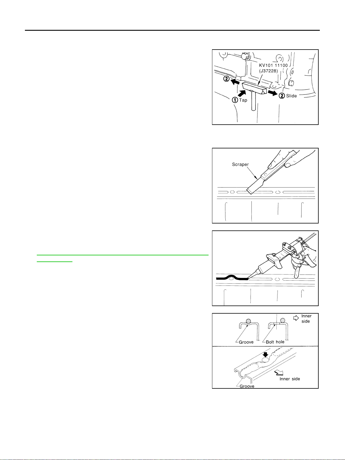
REMOVAL OF LIQUID GASKET
● After removing the mounting nuts and bolts, separate the mating
surface using a seal cutter [SST] and remove the old liquid gas-
ket sealing.
CAUTION:
Be careful not to damage the mating surfaces.
● Tap seal cutter to insert it, and then slide it by tapping on the
side as shown in the figure.
● In areas wh ere th e sea l cut ter [SST] is di f fic ult to use, use p last ic
hammer to lightly tap the parts, to remove it.
CAUTION:
If for some unavoidable reason a tool such as screwdriver
is used, be careful not to damage the mating surfaces.
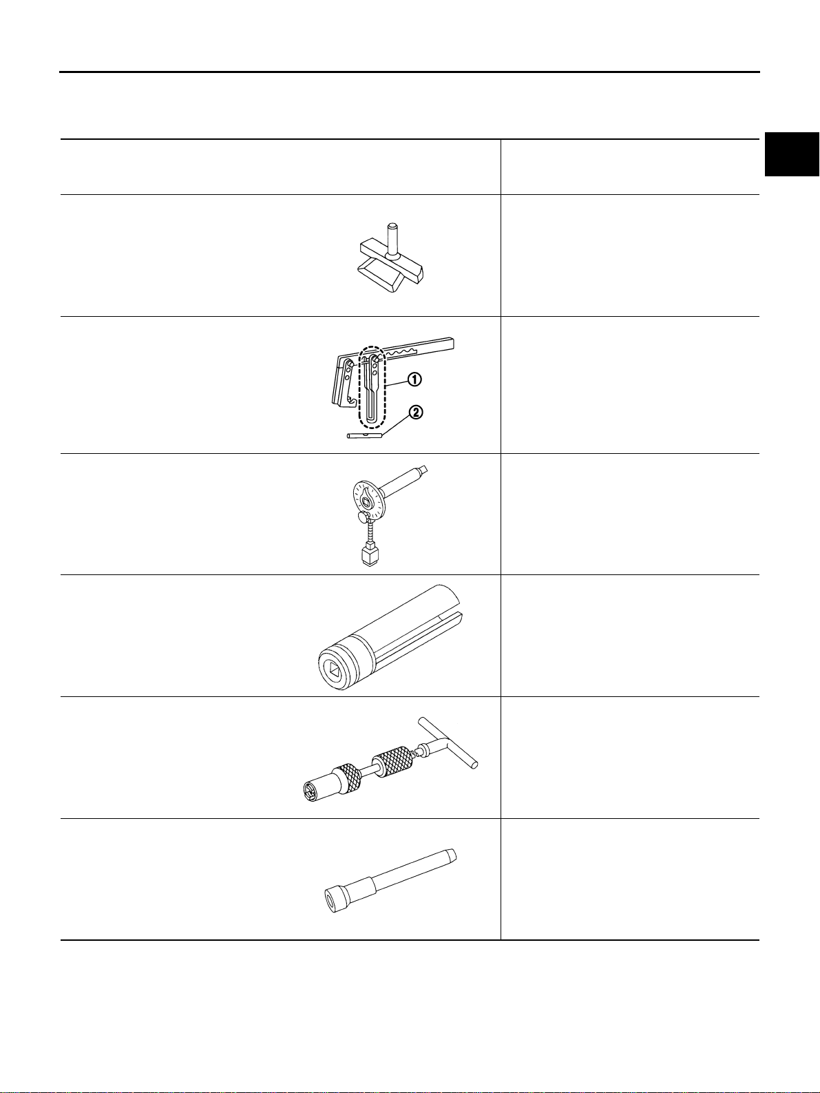
LIQUID GASKET APPLICATION PROCEDURE
1. Using a scraper, remove the old liquid gasket adhering to the liq-
uid gasket app lication surface and the mating surface.
● Remove the liqu id gasket completely from the gro ove of the
liquid gasket application surface, mounting bolts and bolt
holes.
2. Wipe the liquid gasket application surface and the mating sur-
face with white gasoline (lighting and heating use) to remove
adhering moisture, grease and foreign ma terials.
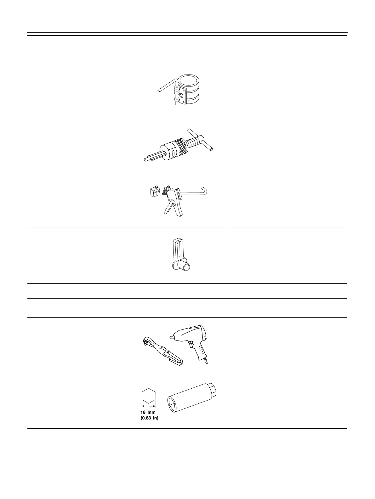
3. Attac h li q uid ga sk et tu be t o the tu be p res se r [ S ST: WS39930000
(—)].
Use Genuine RTV Silicone Sealant or equivalent. Refer to
GI-48, "
RECOMMENDED CHEMICAL PRODUCTS AND
SEALANTS" .
4. Apply the liquid gasket without breaks to the specified location
with the specified dimensions.
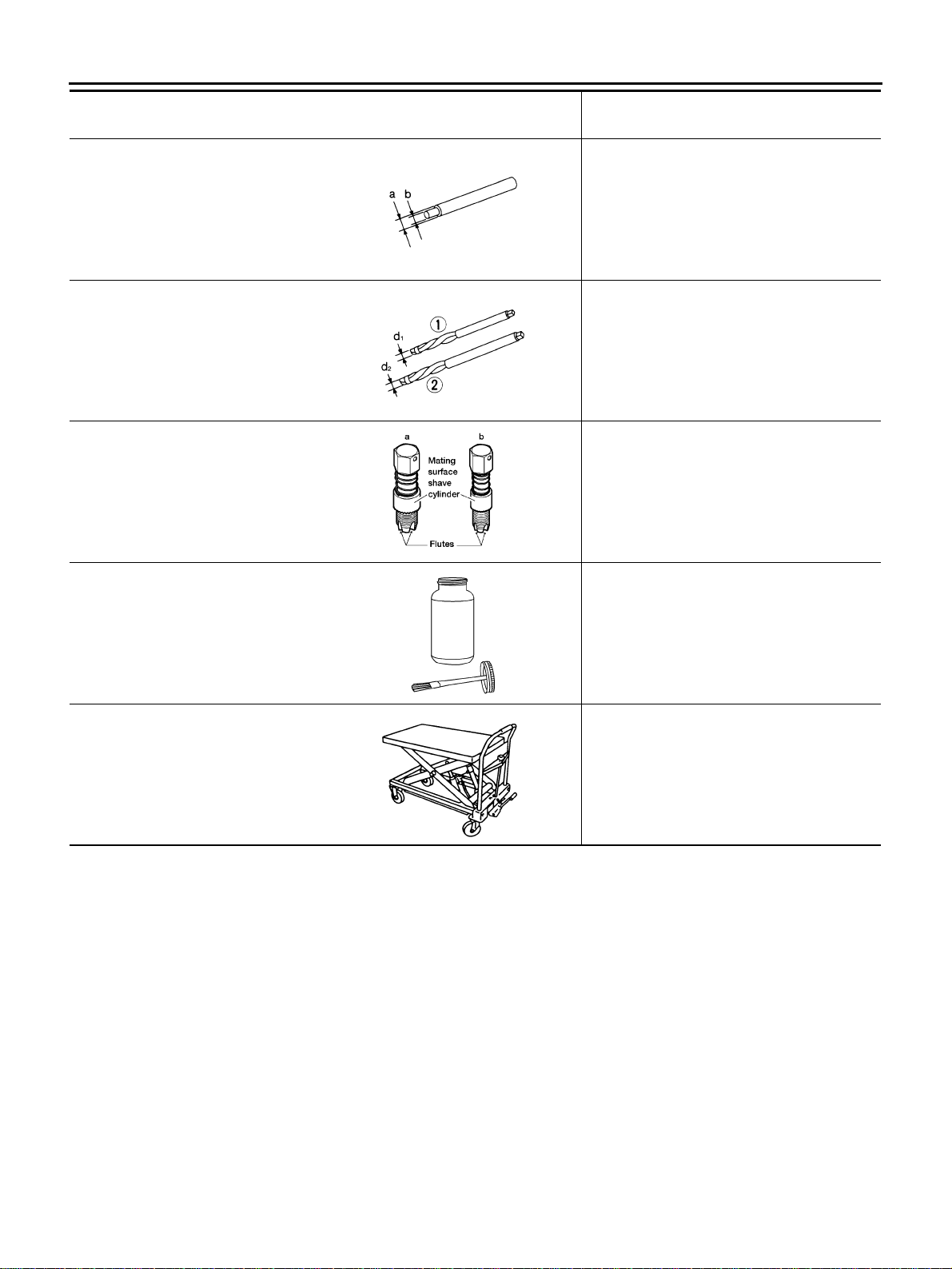
● If there is a groo ve for t he liquid gaske t applica tion, apply th e
liquid gasket to the groove.
● As for the bolt holes, normally apply the liquid gasket inside
the holes. Occasionally, it should be applied outside the
holes. Make sure to read the text of service manual.
● Within 5 minutes of liquid gasket application, install the mating
component.
● If the liquid gasket protrudes, wipe it off immediately.
● Do not retighten mounting nuts or bolts after the installation.
● Wait 30 minutes or more after installation before refilling
engine oil and engine coolant.
CAUTION:
If there are instructions in this manual, observe them.
PBIC0002E
PBIC0003E
EMA0622D
SEM159F
PREPARATION
EM-5
C
D
E
F
G
H
I
J
K
L
M
A
EM
Revision: 2005 March 2005 X-Trail
PREPARATION PFP:00002
Special Service Tools ABS00CIS
The actual shapes of Kent-Moore tools may differ from those of spec ial ser vi ce tool s illust rat ed here.
Tool number
(Kent-Moore No.)
Tool name
Description
KV10111100
(J37228)
Seal cutter
Removing oil pan and front cover, etc.
KV10116200
(J26336-A)
Valve spring compressor
1. KV10115900
(J26336-20)
Attachment
2. KV10109220
(—)
Adapter
Disassembling valve mechani sm
Part (1) is a component of KV10116200
(J26336-A), but Part (2) is not so.
KV10112100
(BT8653-A)
Angle wrench
Tightening bolts for connecting rod bearing
cap, cylinder head, etc. in angle
KV10117100
(J-3647-A)
Heated oxygen sensor wrench
Loosening or tightening heated oxygen
sensors
For 22 mm (0.87 in) width hexagon nut
KV10107902
(J38959)
Valve oil seal puller
Replacing valve oil seal
KV10115600
(J-38958)
Valv e oil seal drift
Installing valve oil seal
S-NT046
PBIC1650E
NT014
NT379
NT011
NT024
EM-6
PREPARATION
Revision: 2005 March 2005 X-Trail
Commercial Service Tools ABS00CIT
EM03470000
(J-8037)
Piston ring compressor
Installing piston assembly into cylinder bore
ST16610001
(J-23907)
Pilot bushing puller
Removing pilot converter (A/T models)
WS39930000
(—)
Tube presser
Pressing the tube of liquid gasket
—
(J-45488)
Quick connector release
Removing fuel tube quick connectors i n
engine room
Tool number
(Kent-Moore No.)
Tool name
Description
NT044
NT045
NT052
PBIC0198E
(Kent-Moore No.)
Tool name
Description
Power tool Loosening nuts and bolts
(—)
Spark plug wrench
Removing and installing spark plug
PBIC0190E
S-NT047

PREPARATION
EM-7
C
D
E
F
G
H
I
J
K
L
M
A
EM
Revision: 2005 March 2005 X-Trail
(—)
Pulley holder
Removing and installing crankshaft pul le y
(—)
Pulley puller
Removing crankshaft pulley
(—)
1. Compression tester
2. Adapter
Checking compression pressure
(J24239-01)
Cylinder head bolt wrench
Loosening and tightening cylinder head bo lt,
and used with the angle wrench [SST:
KV10112100 (BT8653-A)]
a: 13 (0.51) dia.
b: 12 (0.47)
c: 10 (0.39)
Unit: mm (in)
(—)
Valve seat cutter set
Finishing valve seat dimensions
TORX socket Removing and installing flywheel
Size: T55
(—)
Piston ring expander
Removing and installing piston ring
(Kent-Moore No.)
Tool name
Description
ZZA1010D
NT676
ZZA0008D
NT583
S-NT048
PBIC1113E
S-NT030
EM-8
PREPARATION
Revision: 2005 March 2005 X-Trail
(—)
Valve guide drift
Removing and installing valve guide
Intake and Exhaust:
a: 9.5 mm (0.374 in) dia.
b: 5.5 mm (0.217 in) dia.
(—)
Valve guide reamer
1: Reaming valve guide inner hole
2: Reaming hole for oversize valve guide
Intake and Exhaust:
d
1 : 6.0 mm (0.236 in) dia.
d
2 : 10.2 mm (0.402 in) dia.
a: (J-43897-18)
b: (J-43897-12)
Oxygen sensor thread cleaner
Reconditioning the exhaust system thre ads
before installing a new heated oxygen sensor
(Use with anti-seize lubricant shown below.)
a = 18 mm (0.71 in) dia. for zirconia heated
oxygen sensor
b = 12 mm (0.47 in) dia. for titania heated
oxygen sensor
(—)
Anti-seize lubricant i.e.: (Permatex
TM
133AR or equivalent meeting MIL
specification MIL-A-907)
Lubricating oxygen sensor thread cleani ng
tool when reconditioning exhaust syst em
threads
(—)
Manual lift table caddy
Removing and installing the engine
(Kent-Moore No.)
Tool name
Description
S-NT015
S-NT016
AEM488
AEM489
ZZA1210D
NOISE, VIBRATION AND HARSHNESS (NVH) TROUBLESHOOTING
EM-9
C
D
E
F
G
H
I
J
K
L
M
A
EM
Revision: 2005 March 2005 X-Trail
NOISE, VIBRATION AND HARSHNESS (NVH) TROUBLESHOOTING PFP:00003
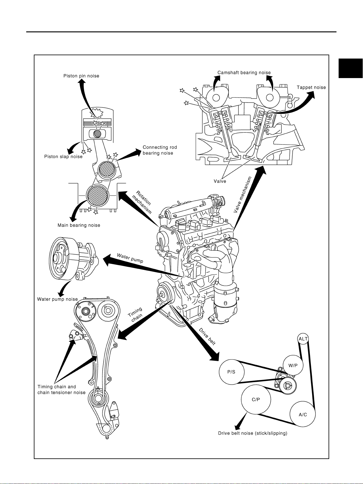
NVH Troubleshooting — Engine Noise ABS00CIU
PBIC2768E

EM-10
NOISE, VIBRATION AND HARSHNESS (NVH) TROUBLESHOOTING
Revision: 2005 March 2005 X-Trail
Use the Chart B elow to Help You Find the Cause of the Symptom. ABS00CIV
1. Locate the area where noise occurs.
2. Confirm the type of noise.
3. Specify the operating condition of engine.
4. Check specified noise source.
If necessary, repair or replace these parts.
A: Closely related B: Related C: Sometimes related —: Not related
Location
of noise
Type of
noise
Operating condition of engine
Source of
noise
Check item
Refer-
ence page
Before
warm-
up
After
warm-
up
When
start-
ing
When
idling
When
racing
While
driving
Top of
engine
Rocker
cover
Cylinder
head
Ticking or
clicking
CA—AB—
Tappet
noise
Va lve cle ara nce EM-46
Rattle C A — A B C
Camshaft
bearing
noise
Camshaft journal oil
clearance
Camshaft runout
EM-40
EM-40
Crank-
shaft pul -
ley
Cylinder
block
(Side of
engine)
Oil pan
Slap or
knock
—A—BB—
Piston pin
noise
Piston to piston pin oil
clearance
Connecting rod bush-
ing oil clearance
EM-99
EM-101
Slap or
rap
A ——BBA
Piston
slap noise
Piston to cylinder bore
clearance
Piston ring side clear-
ance
Piston ring end gap
Connecting rod bend
and torsion
EM-103
EM-100
EM-100
EM-101
Knock A B CBBB
Connect-
ing rod
bearing
noise
Connecting rod bush-
ing oil clearance
Connecting rod bear-
ing oil clearance
EM-101
EM-105
Knock A B — A B C
Main
bearing
noise
Main bearing oil clear-
ance
Crankshaft runout
EM-106
EM-105
Front of
engine
Front
cover
T apping or
ticking
A A—BBB
Timing
chain and
chain ten-
sioner
noise
Timing chain cracks
and wear
Timing chain tensioner
operation
EM-53
EM-49
Front of
engine
Squeak-
ing or fizz-
ing
AB—B—C
Drive belt
(Sticking
or slip-
ping)
Drive belt deflection
EM-11
Creaking A B A B A B
Drive belt
(Slipping)
Idler pulley bearing
operation
Squall
Creak
A B—BAB
Water
pump
noise
Water pump operation
CO-20,
"WATER
PUMP"
DRIVE BELTS
EM-11
C
D
E
F
G
H
I
J
K
L
M
A
EM
Revision: 2005 March 2005 X-Trail
DRIVE BELTS PFP:02117
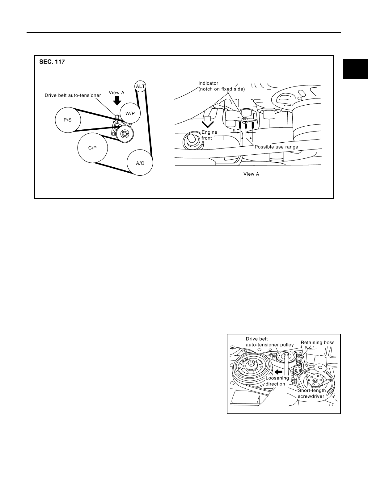
Checking Drive Belt ABS00CIW
WARNING:
Be sure to perform this step when the engine is stopped.
● Make sure that the indicator (notch on fixed side) of drive belt auto-tensioner is within the possible use
range (between three line notches on moving side).
NOTE:
● Check the drive belt auto-tensioner indication when the engine is cold.
● When new drive belt is installed, the indicator (notch on fixed side) should be within the range “a” in the
figure.
● Visually check entire drive belt for wear, damage or cracks.
● If the indicator (notch on fixed side) is out of the possible use range or belt is damaged, replace drive belt.
Tension Adjust me nt ABS00CIX
Belt tensioning is not necessary, as it is automatically adjusted by drive belt auto-tensioner.
Removal and Installation ABS00CIY
REMOVAL
1. Remove splash guard on RH undercover.
2. Hold the hexagonal part in center of drive belt auto-tensioner
pulley with a box wrench securely. Then move the wrench han-
dle in the direction of arrow (loos en in g dir ec tio n of ten si on er).
CAUTION:
● Avoid placing hand in a location where pinching may
occur if the holding tool accidentally comes off.
● Do not loosen the hexag onal part in center of drive belt
auto-tensioner pulley (Do no t turn it counterclockwise). If
turned counterclockwise, the complete drive belt auto-
tensioner must be replaced as a unit, including the pul-
ley.
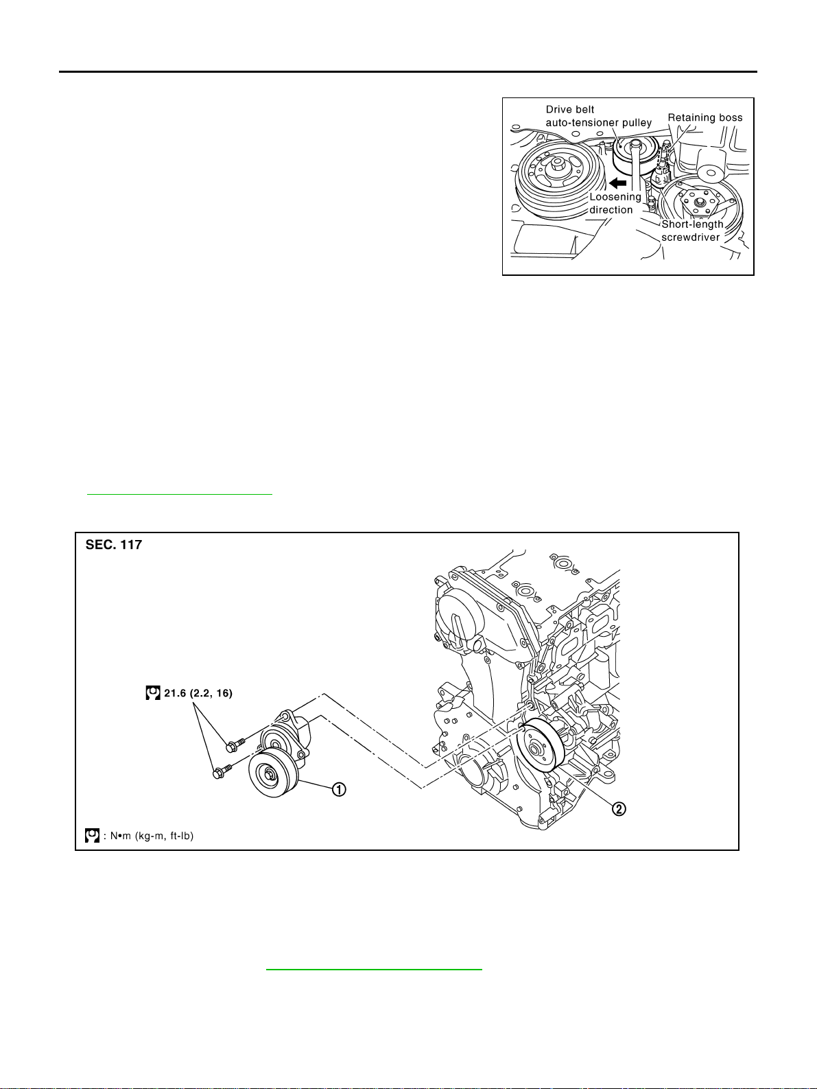
3. Insert a rod approximately 6 mm (0.24 in) in diameter such as
short-length screwdriver into the ho le of the retaining boss to fix drive belt auto-tensioner pulley.
4. Loosen drive belt from water pump pulley i n sequence, and remove it.
PBIC2622E
PBIC2169E
EM-12
DRIVE BELTS
Revision: 2005 March 2005 X-Trail
INSTALLATION
1. Hold the hexagonal part in center of drive belt auto-tensioner
pulley with a box w rench sec urely. Then move the wrench han-
dle in the direction of arrow (loosening direction of tensioner).
CAUTION:
● Avoid placing hand in a location where pinching may
occur if the holding tool accidentally comes off.
● Do not loosen the hexa gonal part in center of drive belt
auto-tensioner pulley (Do n ot turn i t cou nte rcloc kwi se ). If
turned counterclockwise, the complete drive belt auto-
tensioner must be replac ed as a unit, including the pul-
ley.
2. Insert a rod approxim ately 6 mm (0.24 in) in diameter s uch as
short-length screwdriver into the hole of retaining boss to fix drive belt auto-tensioner pulley.
3. Hook drive belt onto all pulleys except for water pump, and then onto water pump pulley finally.
CAUTION:
● Confirm drive belt is completely set to pulleys.
● Check for engine oil, working fluid and engine coolant are not adhered to drive belt and each
pulley groove.
4. Release drive belt auto-tensioner, and apply t ension to drive belt.
5. T urn crankshaft pulley clockwise several times to equalize tension between each pulley.
6. Confirm tension of drive belt at indicator (notch on fixed side) is within the possible use range. Refer to
EM-11, "
Checking Drive Belt" .
Removal and Installation of Drive Belt Auto-Tensioner ABS00CIZ
REMOVAL
CAUTION:
The complete drive belt auto-tensioner must be replaced as a unit, including the pulley.
1. Remove splash guard on RH undercover.
2. Remove drive belt. Refer to EM-11, "
Removal and Installation" .
3. Release the fixed drive belt auto-tensioner pulley.
4. Remove drive belt auto-tensioner.
PBIC2627E
1. Drive belt auto-tensioner 2. Water pump pulley
PBIC2170E

DRIVE BELTS
EM-13
C
D
E
F
G
H
I
J
K
L
M
A
EM
Revision: 2005 March 2005 X-Trail
CAUTION:
Do not loosen the hexagonal part in center of drive belt auto-tensione r pulley (Do not turn it counter-
clockwise). If turned counte rclockwise, th e complete drive belt a uto-tensioner must b e replaced as a
unit, including the pulley.
INSTALLATION
Note the following, and install in the reverse order of removal.
● When installing drive belt auto-t ensioner, be c areful not to interfere with water pump pulley.
CAUTION:
● If there is damage greater than peeled paint, replace drive belt auto-tensioner.
● Do not swap the pulley between new and old drive belt auto-tensioner.

EM-14
AIR CLEANER AND AIR DUCT
Revision: 2005 March 2005 X-Trail
AIR CLEANER AND AIR DUCT PFP:16500
Removal and Installation ABS00CJ0
REMOVAL
1. Remove mass air flow sensor harness clam p.
2. Disconnect harness connector from mass air flow sensor.
3. Disconnect PCV hose.
4. Remove air duct (inlet ), air du cts and air c leaner c ase/ mass ai r flow sen sor a ssembl y disc onne cting thei r
joints.
● Add mating marks as nece s sa ry for easier installation.
5. Remove mass air flow sensor from air cleaner case upper, as necessary.
CAUTION:
Handle mass air flow sensor with the following cares.
● Do not shock it.
● Do not disassemble it.
● Do not touch its sensor.
1. Air cleaner filter 2. Clip 3. Air cleaner case upper
4. Clamp 5. Air duct 6. PCV hose
7. Clamp 8. Bracket 9. Mass air flow sensor
10. O-ring 11. Air duct 12. Air duct (inlet)
13. Clip 14. Collar 15. Grommet
16. Resonator 17. Bracket (A/T models) 18. Mounting rubber
19. Collar 20. Grommet 21. Air cleaner case lower
PBIC2171E
AIR CLEANER AND AIR DUCT
EM-15
C
D
E
F
G
H
I
J
K
L
M
A
EM
Revision: 2005 March 2005 X-Trail
6. Remove resonator in fender lifting left fender protector, as necessary.
INSPECTION AFTER REMOVAL
Inspect air duct assem bl y for cra ck s or tear.
● Replace air duct assembly, if necessary.
INSTALLATION
Note the following, and install in the reverse order of removal.
● Align marks. Attach each joint. Screw clamps firmly.
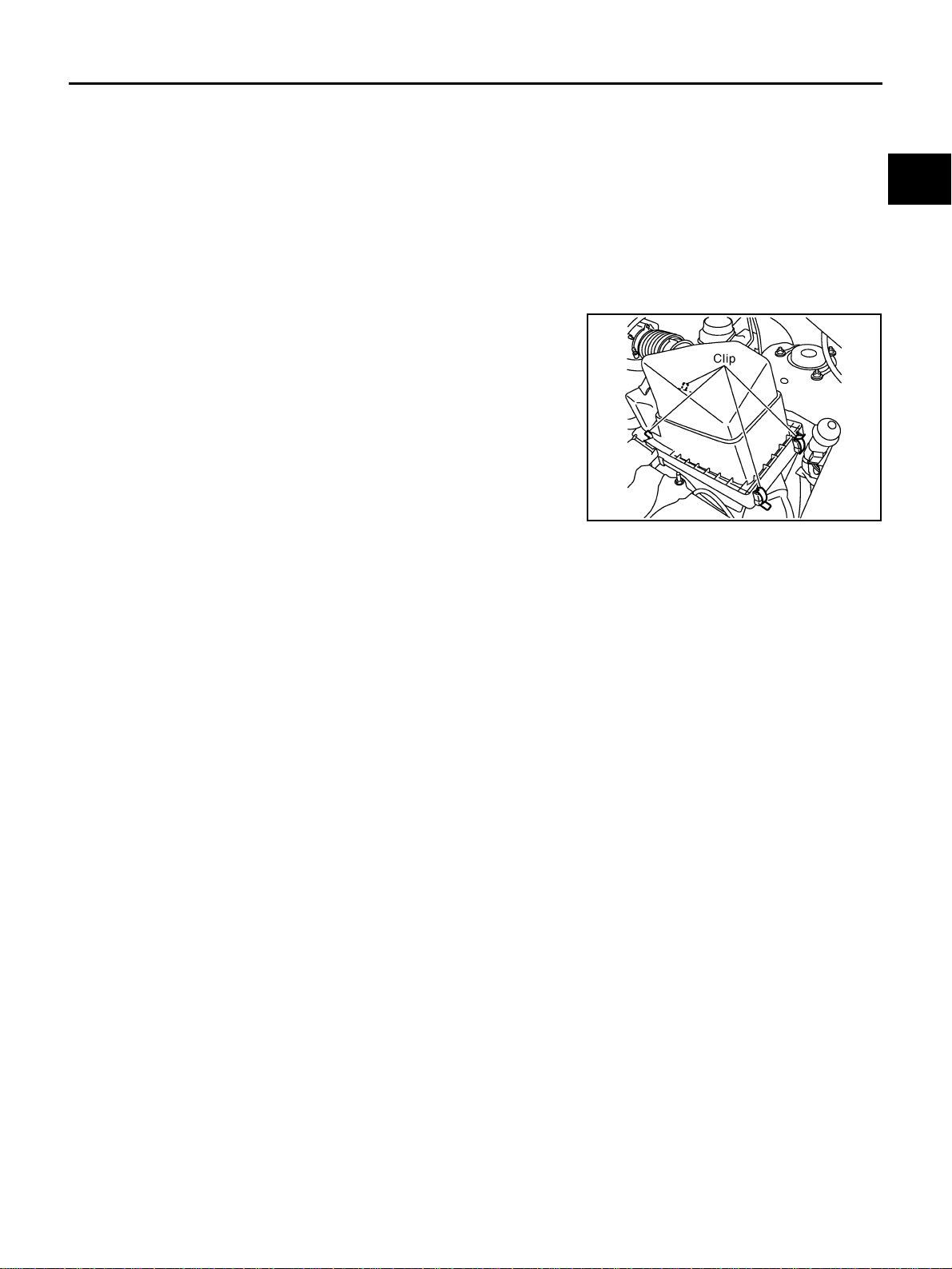
Changing Air Cleaner Filter ABS00CJ1
REMOVAL
1. Unfasten clips and lift up air cleaner case upper.
2. Remove air cleaner filter.
INSTALLATION
Install in the reverse order of removal.
PBIC2749E

EM-16
INTAKE MANIFOLD
Revision: 2005 March 2005 X-Trail
INTAKE MANIFOLD PFP:14003
Removal and Installation ABS00E9L
CAUTION:
Do not remove or disassemble parts unless instructed as shown in the figure.
REMOVAL
1. Release fuel pressure. Refer to EC-90, "FUEL PRESSURE RELEASE" .
1. Vacuum hose 2. Harness bracket 3. Vacuum hose
4.
EV A P ca ni st er pu r ge vol um e c on t ro l
solenoid valve
5. Vacuum hose 6. PCV hose
7. Harness bracket 8. Intake manifold collector 9. O-ring
10. Hose connector 11. Hose bracket 12. Gasket
13. Water hose 14. Water hose 15. Electric throttle control actuator
16. Intake manifold rear support 17. Gasket 18. Intake manifold
19. Gasket 20. Intake manifold suppor t 21. Vacuum hose
22. Vacuum hos e 23. Vacuum hose 24. Vacuum reservoir tank
25. VIAS control solenoid valve 26. Vacuum reservoir tank bracket 27. Filter
PBIC2698E

INTAKE MANIFOLD
EM-17
C
D
E
F
G
H
I
J
K
L
M
A
EM
Revision: 2005 March 2005 X-Trail
2. Remove engine cover.
CAUTION:
Be careful not to damage or scratch engine cover.
3. Remove air cleaner case upper, mass air flow sensor and air duct assembly. Refer to EM-14, "
AIR
CLEANER AND AIR DUCT" .
4. Remove quick connector caps, and disconnect quick connector
at the engine side. Refer to EM-30, "
FUEL INJECTOR AND
FUEL TUBE" .
5. Remove electric throttle control a c tuator with the following procedure:
a. Disconnect harness connector.
b. Loosen mounting bolts in reverse order as shown in the figure,
and remove electric throttle control actuator and gasket.
CAUTION:
● Handle carefully to avoid any shock to electric throttle
control actuator.
● Do not disassemble.
6. Disconnect harness, vacuum hoses and PCV hose from intake manifold collector, and move them aside.
7. Remove intake manifold rear support.
PBIC2602E
PBIC2175E
EMJ1612D
EM-18
INTAKE MANIFOLD
Revision: 2005 March 2005 X-Trail
8. Loosen mounting nuts and bolts in reverse orde r as shown in
the figure, and remove intake manifold collector and gasket.
CAUTION:
Cover engine openings to avoid entry of foreign materials.
NOTE:
Disregard No. 8 when loosening.
9. Disconnect power steering piping from intake manifold, and move them aside. Refer to PS-33, "
HYDRAU-
LIC LINE" .
10. Remove intake manifold support.
11. Disconnect sub-harness from fuel injector. Refer to EM-30, "
FUEL INJECTOR AND FUEL TUBE" .
12. Remove fuel tube and f uel injector assembly fro m intake manifold. Refer to EM-30, "
FUEL INJECTOR
AND FUEL TUBE" .
13. Loosen mounting nuts and bolts in reverse order as shown in
the figure, and remove intake manifold and gasket.
CAUTION:
● Cover engine open ings to avoid entry of foreign materi-
als.
● Do not disassemble intake manifold.
NOTE:
Disregard No. 6 when loosening.
14. Remove EVAP canister purge volume control solenoid valve from intake manifold collector, if necessary.
15. Remove vacuum reservoir tank and VIAS control solenoid valve from intake manifold, if necessary.
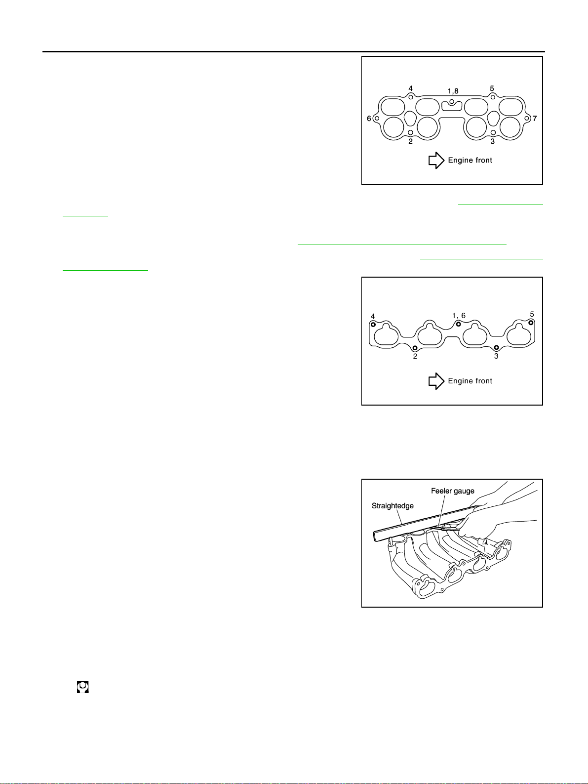
INSPECTION AFTER REMOVAL
Surface Distortion
● Using a straightedge and a feeler gauge, check the surface dis-
tortion of both the intake manifold collector mating surface and
the intake manifold mating surfaces.
● If it excee ds t he lim it , re pl ac e in take manifold and/or intake man-
ifold collector.
INSTALLATION
Note the following, and install in the reverse order of removal.
Intake Manifold
● If stud bolts were removed, install them and tighten to the specified torque below.
SBIA0230E
PBIC2699E
Limit : 0.1 mm (0.004 in)
KBIA0235E
: 10.8 N·m (1.1 kg-m, 8 ft-lb)
INTAKE MANIFOLD
EM-19
C
D
E
F
G
H
I
J
K
L
M
A
EM
Revision: 2005 March 2005 X-Trail
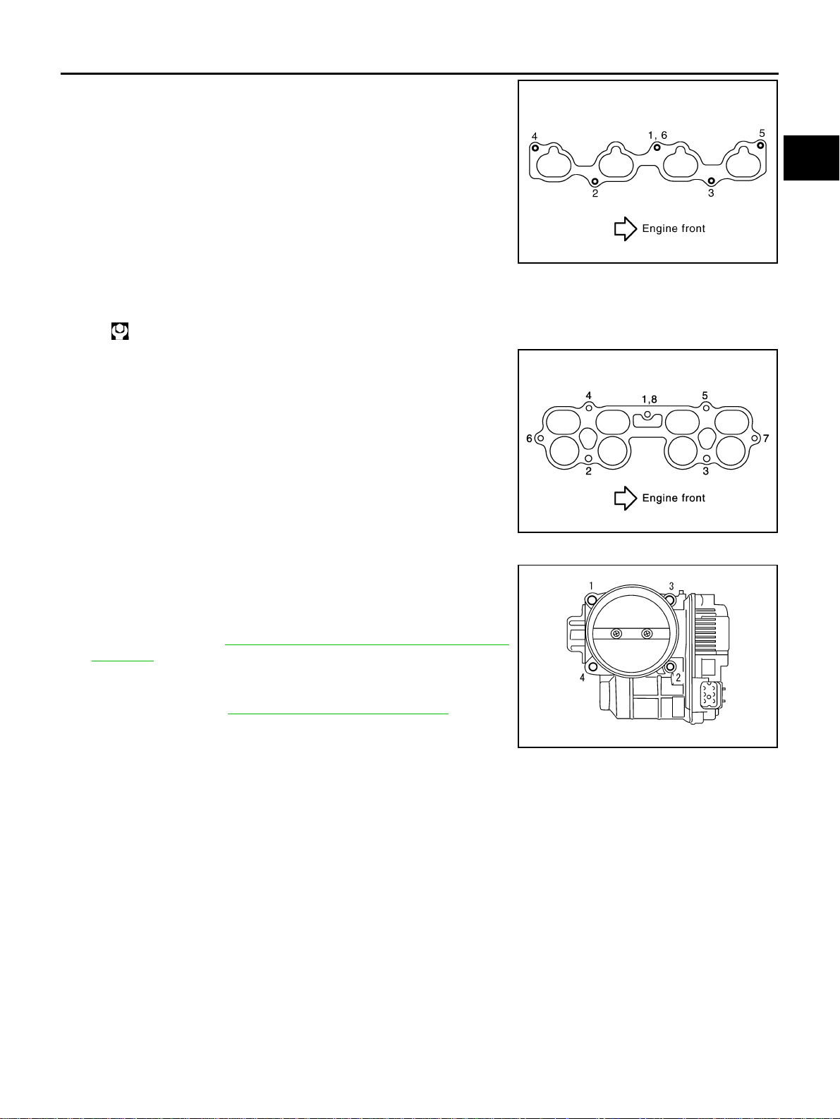
● Tighten in numerical order as shown in the figure.
NOTE:
No. 6 means double tightening of bolt No. 1.
Intake Manifold Collector
● If stud bolts were removed, install them and tighten to the specified torque below.
● Tighten in numerical order as shown in the figure.
NOTE:
No. 8 means double tightening of bolt No. 1.
Electric Throttle Control Actuator
● Tighten mounting bolts equa lly and diagonally in severa l steps
and in numerical order as shown in the figure.
● Perform the “ Thr o t tle Valve Closed Position Lear ni ng ” wh en ha r-
ness connector of electric throttle control actuator is discon-
nected. Refer to EC-88, "
Throttle Valve Closed Position
Learning" .
● Perform the “Idle Air Volume Learning” and “Throttle Valve
Closed Position Learn ing” when electric thro ttle control ac tuator
is replaced. Refer to EC-88, "
Idle Air Volume Learning" .
INSPECTION AFTER INSTALLATION
Make sure there are no fuel leaks at connections before installing engine cover with the following procedure:
1. Apply fuel pressure to fuel lines with turning ignition switch “ON” (with the engine stopped). Then make
sure there are no fuel leaks at connections.
NOTE:
Use mirrors for checking on invisible points.
2. Start the engine. With en gine speed increased, make sure again there are no fuel leaks at connections.
CAUTION:
Do not touch the engine immediately after stopped as the engine becomes extremely hot.
PBIC2699E
: 10.8 N·m (1.1 kg-m, 8 ft-lb)
SBIA0230E
EMJ1612D
EM-20
EXHAUST MANIFOLD AND THREE WAY CATALYST
Revision: 2005 March 2005 X-Trail
EXHAUST MANIFOLD AND THREE WAY CATALYST PFP:14004
Removal and Installation ABS00CJ4
REMOVAL
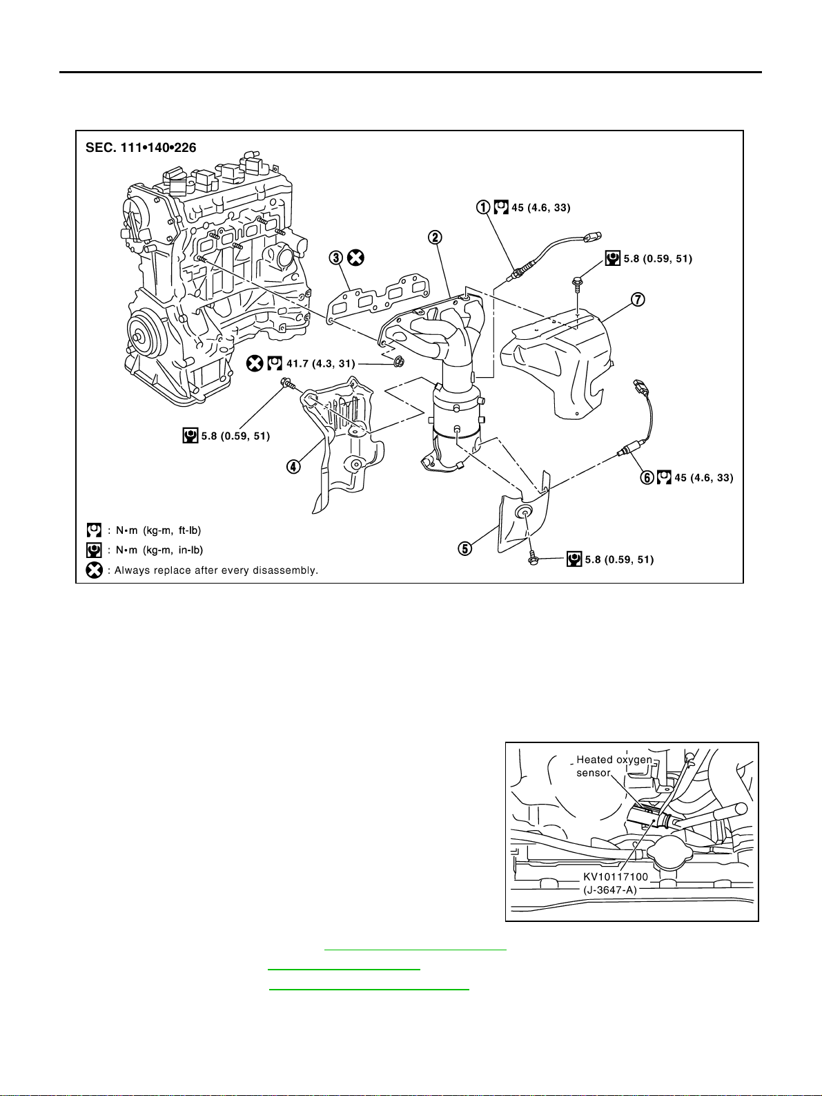
1. Remove heated oxygen sensors with the following procedure:
a. Disconnect harness connector of each heated oxygen sensor, and harness from bracket and middle
clamp.
b. Using the heated oxygen sensor wrench [SST], remove heated
oxygen sensors.
CAUTION:
● Be careful not to damage heated oxygen sensor.
● Discard any heated oxygen sensor which has been
dropped from a height of mo re tha n 0 .5 m (1 9.7 in) onto a
hard surface such as a concrete floor; replace with a new
one.
2. Remove exhaust front tube. Refer to EX-2, "
EXHAUST SYSTEM" .
3. Remove drive belt. Refer to EM-11, "
DRIVE BELT S" .
4. Remove alternator. Refer to SC-20, "
CHARGING SYSTEM" .
5. Remove exhaust manifold cover (upper).
1. Heated oxygen sensor 1 2.
Exhaust manifold and three way cat-
alyst assembly
3. Gasket
4. Three way catalyst cover 5. Exhaust manifold cover (lower) 6. Heated oxygen sensor 2
7. Exhaust manifold cover (upper)
PBIC2750E
PBIC2700E

EXHAUST MANIFOLD AND THREE WAY CATALYST
EM-21
C
D
E
F
G
H
I
J
K
L
M
A
EM
Revision: 2005 March 2005 X-Trail
6. Loosen nuts in reverse order as shown in the figure to remove
exhaust manifold and three way catalyst assembly.
NOTE:
Disregard No. 6 and 7 when loosening.
7. Remove gasket.
CAUTION:
Cover engine openings to avoid entry of foreign materials.
8. Remove exha ust manifold cove r (lower) and three way catalyst cover from exha ust manifold and t hree
way catalyst assembly.
INSPECTION AFTER REMOVAL
Surface Distortion
● Using a straightedge and a feeler gauge, check the surface dis-
tortion of exhaust manifold and three way catalyst assembly
mating surface.
● If it exceeds the limit, replace exhaust manifold and three way
catalyst assembly.
INSTALLATION
Note the following, and install in the reverse order of removal.
Exhaust Manifold
● If stud bolts were removed, install them and tighten to the specified torque below.
● Tighten nuts in numerical order as shown in the figure.
NOTE:
No. 6 and 7 mean double tightening of bolts No. 1 and 3.
Heated Oxygen Sensor
CAUTION:
● Before installing new heated oxygen sensor, clean exhaust system threads using a heated oxygen
sensor thread cleaner (commercial service tool: J-43897-18 or J-43897-12) and apply anti-seize
lubricant (commercial service tool).
● Do not over torque h ea ted ox yg en sensor. Doing so may cause dama ge to hea t ed ox yg en se ns or,
resulting in the “MIL” coming on.
PBIC2701E
Limit : 0.3 mm (0.012 in)
KBIA0046E
: 14.7 N·m (1.5 kg-m, 11 ft-lb)
PBIC2701E

EM-22
OIL PAN AND OIL STRAINER
Revision: 2005 March 2005 X-Trail
OIL PAN AND OIL STRAINER PFP:11110
Removal and Installation ABS00CJ5
REMOVAL
WARNING:
To avoid the danger of being scalded, do not drain the engine oil when the engine is hot.
1. Remove RH and LH undercovers.
NOTE:
When removing oil pan (lower) or oil strainer only, this step is unnecessary.
2. Drain engine oil. Refer to LU-7, "
Changing Engine Oil" .
CAUTION:
● Perform this step when the engine is cold .
● Do not spill engine oil on drive belt.
3. Remove oil pan (lower) with the following procedure:
1. Oil level gauge 2. Oil level gauge guide 3 . O-rin g
4. Oil pan (upper) 5. Cylinder block 6. O-ring
7. Oil filter 8. O- ring 9. Drain plug washer
10. Oil strainer 11. Drain plug 12. Oil pan (lower)
13. Rear plate cover
PBIC2702E
OIL PAN AND OIL STRAINER
EM-23
C
D
E
F
G
H
I
J
K
L
M
A
EM
Revision: 2005 March 2005 X-Trail
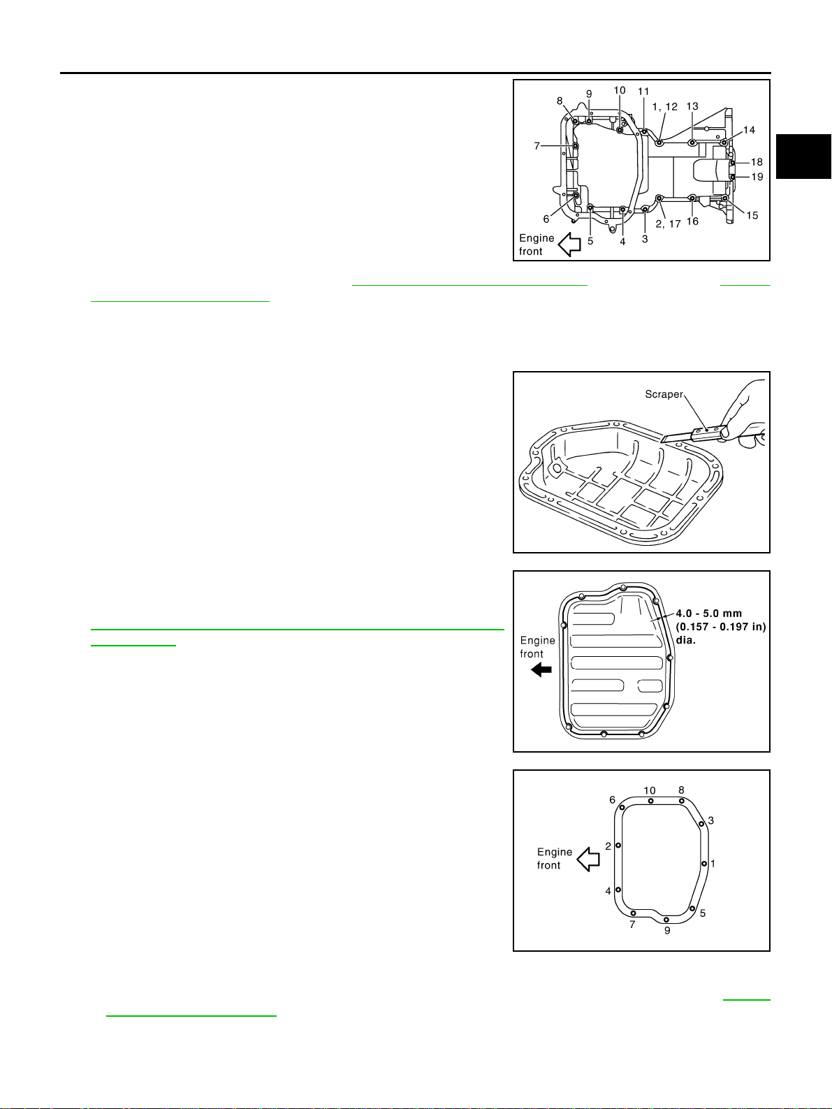
a. Loosen mounting bolts in reverse order as shown in the figure
with power tool.
b. Insert the seal cutte r [SST] between oil pan (upper) an d oil pan
(lower).
CAUTION:
● Be careful not to damage the mating surfaces.
● Do not insert a screwdri ver, this will damage the mating
surfaces.
c. Slide seal cutter by tapping on the side of the tool with a ham-
mer. Remove oil pan (lower).
4. Remove oil strainer.
5. Remove oil pan (upper) with the following procedure:
a. Remove drive belt. Refer to EM-11, "
DRIVE BELTS" .
b. Remove oil filter. Refer to LU-9, "
OIL FILTER" .
c. Remove A/C compressor with piping connected. And locate it aside temporarily with ropes or equivalent
not to disturb the following work. Refer to ATC-122, "
Removal and Ins tallation of Compresso r" (Automatic
A/C models) or MTC-82, "
Removal and Installation of Compressor" (Manual A/C models).
d. Remove oil level gauge guide.
e. Remove exhaust front tube and its support. Refer to EX-2, "
EXHAUST SYSTEM" .
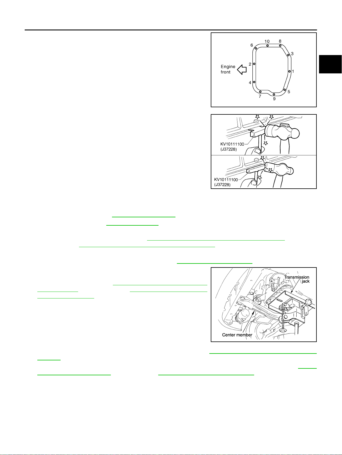
f. Set a suitable transmission jack under transaxle and hoist the
engine with engine slinger, and then remove center member
with power tool. Refer to EM-74, "
Removal and Installation
(2WD Models)" (2WD models ) or EM-78, "Removal and Instal-
lation (AWD Models)" (AWD models).
g. Remove rear engine mounting bracket (2WD models). Refer to EM-74, "
Removal and Install ation (2WD
Models)" .
h. Remove rear plate cover, and four transaxle joint bolts which pierce oil pan (upper). Refer to MT-17,
"TRANSAXLE ASSEMBLY" (M/T models) or AT-269, "TRANSAXLE ASSEMBLY" (A/T models).
PBIC2703E
SEM365E
PBIC0257E
EM-24
OIL PAN AND OIL STRAINER
Revision: 2005 March 2005 X-Trail
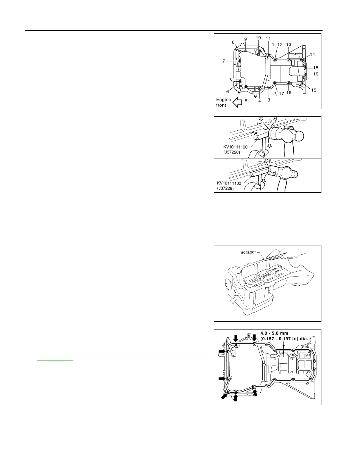
i. Loosen bolts in rev erse orde r as show n in the fi gure with po wer
tool.
NOTE:
Disregard No.12 and 17 when loosening.
j. Insert the se al cutter [SST] between oil pan (upper) and cylinder
block, and sl ide it by tapping o n the side o f the too l with a ham-
mer. Remove oil pan (upper).
CAUTION:
● Be careful not to damage the mating surfaces.
● Do not insert a screwdriver, this will damage the mating
surfaces.
6. Remove O-rings at front cover side.
INSPECTION AFTER REMOVAL
Clean oil strainer if any object attached.
INSTALLATION
1. Install oil pan (upper) with the following procedure:
a. Use a scraper to remove old liquid gasket from mating surfaces.
● Also remove the ol d liquid gasket from mating su rface of cyl-
inder block.
● Remove old liquid gasket from the bolt holes and threads.
CAUTION:
Do not scratch or damage the mating surfac es when clea n-
ing off old liquid gasket.
b. Apply a continuous bead of liquid gasket with the tube presser
[SST: WS39930000 ( — )] as shown in the figure.
Use Genuine RTV Silicone Sealant or equivalent. Refer to
GI-48, "
RECOMMENDED CHEMICAL PRODUCTS AND
SEALANTS" .
CAUTION:
● Apply liquid gaske t to outside of bolt hole for the posi-
tions shown by arrows.
● Attaching should be done within 5 minutes after coating.
c. Install new O-rings at front cover side.
PBIC2704E
SEM365E
MEM108A
SBIA0253E
OIL PAN AND OIL STRAINER
EM-25
C
D
E
F
G
H
I
J
K
L
M
A
EM
Revision: 2005 March 2005 X-Trail
d. Tighten bolts in numerical order as shown in the figure.
NOTE:
● No. 12 and 17 me an double tightening of bolts No. 1 and 2.
● Refer to th e following for locating bolts.
e. Tighten transaxle joint bolts. Refer to MT-17, "
TRANSAXLE ASSEMBLY" (M/T models) or AT-269,
"TRANSAXLE ASSEMBLY" (A/T models).
f. Install rear plate cover.
2. Install oil strainer.
3. Install oil pan (lower) with the following procedure:
a. Use a scraper to remove old liquid gasket from mating surfaces.
● Also remove old li quid gasket from m ating surface of oil pan
(upper).
● Remove old liquid gasket from the bolt holes and thread.
CAUTION:
Do not scratch or damage the mating surfac es when clean -
ing off old liquid gasket.
b. Apply a continuous bead of liquid gasket with the tube presser
[SST: WS39930000 ( — )] as shown in the figure.
Use Genuine RTV Silicone Sealant or equivalent. Refer to
GI-48, "
RECOMMENDED CHEMICAL PRODUCTS AND
SEALANTS" .
CAUTION:
Attaching should be done within 5 minutes after coating.
c. Tighten bolts in numerical order as shown in the figure.
4. Install oil pan drain plug.
● Refer to the figure of comp onents of former page for installation direc tion of washer. Refer to EM-22,
"Removal and Installation" .
5. Install in the reverse order of removal after this step.
M6 × 20 mm (0.79 in) : No. 18, 19
M8 × 25 mm (0.98 in) : No. 1, 2, 3, 11
M8 × 45 mm (1.77 in) : No. 4, 10, 13, 14, 15, 16
M8 × 100 mm (3.97 in) : No. 5, 6, 7, 8, 9
PBIC2704E
SEM958F
SBIA0254E
PBIC2703E

EM-26
OIL PAN AND OIL STRAINER
Revision: 2005 March 2005 X-Trail
NOTE:
Pour engine oil at least 30 minutes after oil pan is installed.
INSPECTION AFTER INSTALLATION
1. Check the engine oil level, and adjust the level. Refer to LU-6, "ENGINE OIL" .
2. Start the engine, and make sure there is no leaks of engine oil.
3. Stop the engine and wait for 10 minutes.
4. Check the engine oil level again. Refer to LU-6, "
ENGINE OIL" .
IGNITION COIL
EM-27
C
D
E
F
G
H
I
J
K
L
M
A
EM
Revision: 2005 March 2005 X-Trail
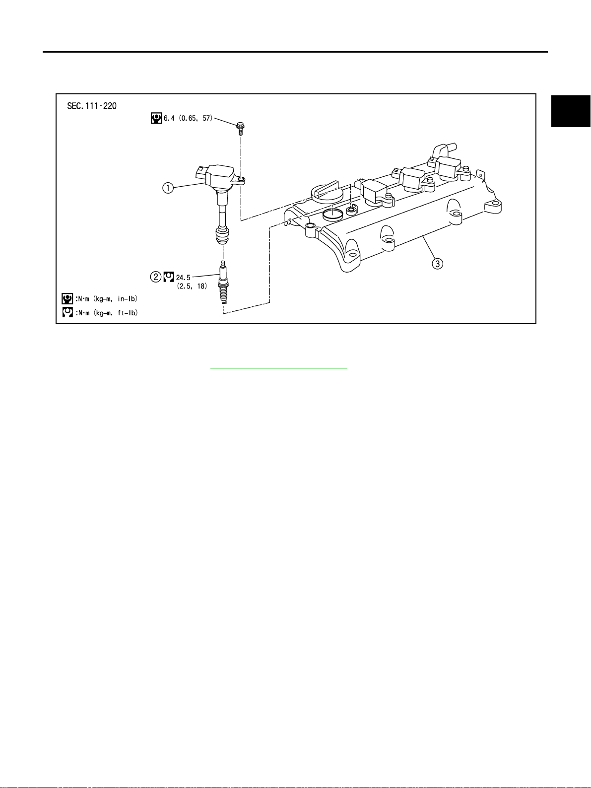
IGNITION COIL PFP:22448
Removal and Installation ABS00CJ6
REMOVAL
1. Remove engine cover. Refer to EM-16, "INTAKE MANIFOLD" .
2. Disconnect harness connector from ignition coil.
3. Remove ignition coil.
CAUTION:
Do not drop or shock it.
INSTALLATION
Install in the reverse order of removal.
1. Ignition coil 2. Spark plug 3. Rocker cover
KBIA1974J
EM-28
SPARK PLUG (PLATINUM-TIPPED TYPE)
Revision: 2005 March 2005 X-Trail
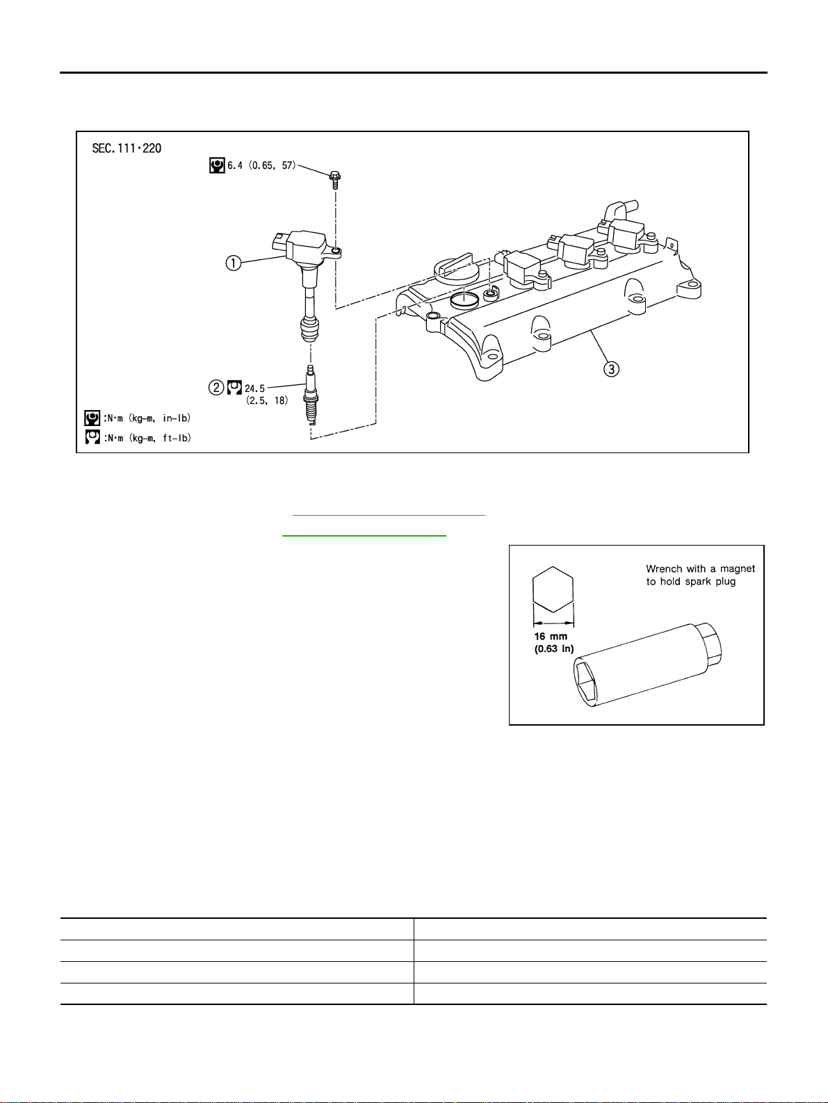
SPARK PLUG (PLATINUM-TIPPED TYPE) PFP:22401
Removal and Installation ABS00DCN
REMOVAL
1. Remove engine cover. Refer to EM-16, "INTAKE MANIFOLD" .
2. Remove ignition coil. Refer to EM-27, "
IGNITION COIL" .
3. Remove spark plug with a spark plug wrench (commercial ser-
vice tool).
CAUTION:
Do not drop or shock it.
INSPECTION AFTER REMOVAL
Use standard type spark plug for normal condition.
Hot type sp ark plug is suitable when fouling occurs with standard type spark plug under conditions such as:
● Frequent engine starts
● Low ambient temperatures
Cold type spark plug is suitable when spark plug knock occurs with standard type spark plug under conditions
such as:
● Extended highway driving
● Frequent high engine revolution
1. Ignition coil 2. Spark plug 3. Rocker cov er
KBIA1974J
SEM294A
Make NGK
Standard type PLFR5A-11
Hot type PLFR4A-11
Cold type PLFR6A-11
Gap (Nominal) : 1.1 mm (0.043 in)

SPARK PLUG (PLATINUM-TIPPED TYPE)
EM-29
C
D
E
F
G
H
I
J
K
L
M
A
EM
Revision: 2005 March 2005 X-Trail
CAUTION:
● Do not drop or shock spark pl ug.
● Do not use wire brush for cleaning.
● If plug tip is covered with carbon, spark plug cleaner may
be used.
● Checking and adjusting plug gap is not required between
change intervals.
INSTALLATION
Install in the reverse order of removal.
Cleaner air pressure:
Less than 588 kPa (6 kg/cm
2
, 85 psi)
Cleaning time:
Less than 20 seconds
SMA773C
SMA806CA
EM-30
FUEL INJECTOR AND FUEL TUBE
Revision: 2005 March 2005 X-Trail
FUEL INJECTOR AND FUEL TUBE PFP:16600
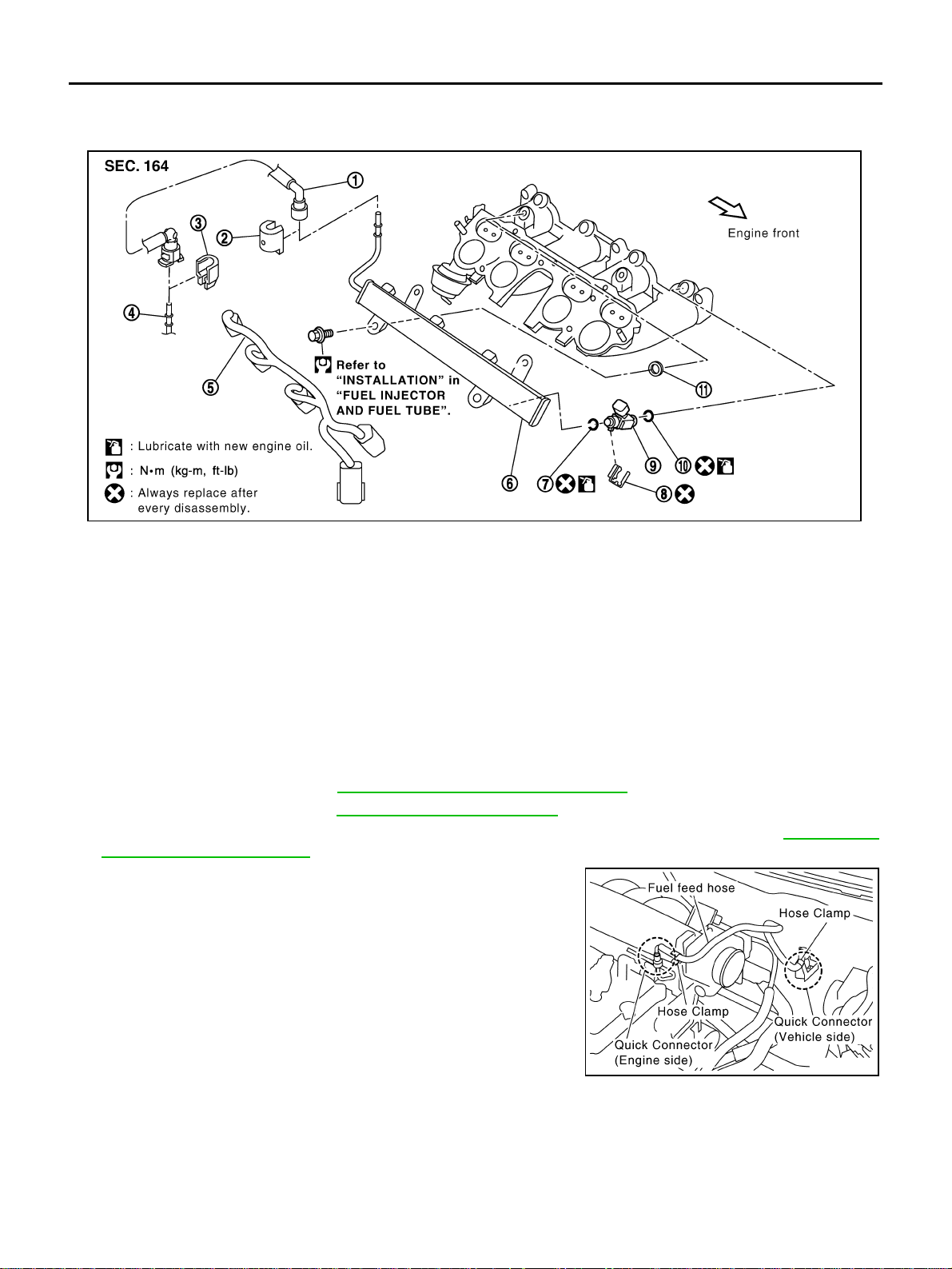
Removal and Installation ABS00CJ9
CAUTION:
Do not remove or disassemble parts unless instructed as shown in the figure.
REMOVAL
WARNING:
● Put a “CAUTION: INFLAMMABLE” sign in the workshop.
● Be sure to work in a well ventilated area and furnish workshop with a CO2 fire extinguisher.
● Do not smoke while servicing fuel system. Keep open flames and sparks away from the work area.
1. Release fuel pressure. Refer to EC-90, "FUEL PRESSURE RELEASE" .
2. Remove engine cover. Refer to EM-16, "
INTAKE MANIFOLD " .
3. Remove air cleaner case upper, mass air flow sensor and air duct assembly. Refer to EM-14, "
AIR
CLEANER AND AIR DUCT" .
4. Disconnect quick connectors at the engine side and the vehicle
side as follows, and remove fuel feed hose.
CAUTION:
Disconnect quick co nnector by using the quick connector
release [SST: J-45488], not by pickin g out retainer tabs.
NOTE:
There is quick connector for the engine side and for the vehicle
side, and they have different shapes. But disconnection is same
procedure. The following procedure sh ows the engine side.
1. Fuel feed hose 2. Quick connector cap (engine side) 3. Quick connector cap (vehicle side)
4. Centralized under-floor pipin g 5. Sub-harness 6. Fuel tube
7. O-ri n g (black) 8. Clip 9. Fuel injector
10. O-ring (green) 11. Insul ato r
PBIC2179E
PBIC2175E
Loading...