


XTrail T30 2005
Table of contents
 Loading...
AUTOMATIC TRANSAXLE
C TRANSMISSION/TRANSAXLE
A
B
SECTION AT
CONTENTS
INDEX FOR DTC ........................................................ 5
Alphabetical Index .................................................... 5
DTC No. Index ......................................................... 6
PRECAUTIONS .......................................................... 7
Precautions for Supplementa l Restraint System
(SRS) “AIR BAG” and “SEAT BELT PRE-TEN-
SIONER” .................................................................. 7
Precautions for On Board Diagnostic (OBD) System
of A/T and Engine .................................................... 7
Precautions .............................................................. 7
Service Notice or Precautions .................................. 9
Wiring Diagrams and Trouble Diagnosis ................ 10
PREPARATION ..................................... .....................11
Special Service Tools ..............................................11
Commercial Service Tools ...................................... 15
A/T FLUID ................................................................. 17
Checking A/T Fluid ................................................. 17
Changing A/T Fluid ..................... ....... ...... ....... ....... 18
A/T Fluid Cooler Cleaning ...................................... 18
A/T CONTROL SYSTEM .......................................... 21
Cross-Sectional View ............................................. 21
Shift Mechanism ..................................................... 22
TCM Function ........... ...... ....... ...... ....... ...... ....... ....... 31
CAN Communication .............................................. 32
Input/Output Signal of TCM .................................... 32
Line Pressure Control ........... ...... ....... ...... ....... ....... 33
Shift Control ........................................................... 34
Lock-Up Control ..................................................... 35
Engine Brake Control (Overrun Clutch Control) ..... 36
Control Valve ............ ...... ....... ...... ........................... 38
ON BOARD DIAGNOSTIC (OBD) SYSTEM ............ 39
Introduction ............................................................ 39
OBD-II Function for A/T System ............................. 39
One or Two Trip Detection Logic of OBD-II ............ 39
OBD-II Diagnostic Trouble Code (DTC) ................. 39
Malfunction Indicator Lamp (MIL) ........................... 42
TROUBLE DIAGNOSIS ............................................ 43
DTC Inspection Priority Chart ................................ 43
Fail-Safe ................................ ................................. 43
How to Perform Trouble Diagnoses for Quick and
AUTOMATIC TRANSAXLE
Accurate Repair ......................................................45
A/T Electrical Parts Location ..................................50
Circuit Diagram .......................................................51
Inspections before Trouble Diagnosis ....................52
Road Test ...............................................................57
Check before Engine Is Started ..............................57
Check at Idle ...........................................................58
Cruise Test — Part 1 .............................................. 60
Cruise Test — Part 2 .............................................. 63
Cruise Test — Part 3 .............................................. 64
Vehicle Speed When Shifting Gears ......................66
Vehicle Speed When Performing and Releasing
Lock-Up ..................................................................66
Symptom Chart .......................................................67
TCM Terminals and Reference Value .....................77
CONSULT-II Function (A/T) ................... ...... ....... ....80
Diagnostic Procedure Without CONSULT-II ........... 91
DTC U1000 CAN COMMUNICATION LINE .............. 95
Description ................... ...... ....... ...... ........................ 95
On Board Diagnosis Logic ......................................95
Possible Cause .......................................................95
DTC Confirmation Procedure ................................. 95
Wiring Diagram — AT — CAN ................................96
Diagnostic Procedure .............................................97
DTC P0705 PARK/NEUTRAL POSITION (PNP)
SWITCH ....................................................................98
Description ................... ...... ....... ...... ........................ 98
CONSULT-II Reference Value ............... ...... ....... ....98
On Board Diagnosis Logic ......................................98
Possible Cause .......................................................98
DTC Confirmation Procedure ................................. 98
Wiring Diagram — AT — PNP/SW .........................99
Diagnostic Procedure ...........................................101
DTC P0710 A/T FLUID TEMPERATURE SENSOR
CIRCUIT ..................................................................104
Description ................... ...... ....... ...... ......................104
CONSULT-II Reference Value ............... ...... ....... ..104
On Board Diagnosis Logic ....................................104
Possible Cause .....................................................104
DTC Confirmation Procedure ...............................104
AT
D
E
F
G
H
I
J
K
L
M
Revision: 2005 March 2005 X-Trail
AT-1

Wiring Diagram — AT — FTS ...............................105
Diagnostic Procedure ...........................................106
Component Inspection ..........................................108
DTC P0720 VEHI CLE SPEED SENSOR ·A/T (REV -
OLUTION SENSOR) ...............................................109
Description ................ .......................... ..................109
CONSULT-II Reference Value ..............................109
On Board Diagnosis Logic ....................................109
Possible Cause .....................................................109
DTC Confirmation Procedure ................... ....... .....109
Wiring Diagram — AT — VSSA/T ..........................111
Diagnostic Procedure ...........................................112
DTC P0725 ENGINE SPEED SIGNAL ...................115
Description ................ .......................... ..................115
CONSULT-II Reference Value ..............................115
On Board Diagnosis Logic ....................................115
Possible Cause .....................................................115
DTC Confirmation Procedure ................... ....... .....115
Wiring Diagram — AT — ENGSS .........................117
Diagnostic Procedure ...........................................118
DTC P0731 A/T 1ST GEAR FUNCTION .................120
Description ................ .......................... ..................120
On Board Diagnosis Logic ....................................120
Possible Cause .....................................................120
DTC Confirmation Procedure ................... ....... .....120
Wiring Diagram — AT — 1STSIG .........................122
Diagnostic Procedure ...........................................123
DTC P0732 A/T 2ND GEAR FUNCTION ................125
Description ................ .......................... ..................125
On Board Diagnosis Logic ....................................125
Possible Cause .....................................................125
DTC Confirmation Procedure ................... ....... .....125
Wiring Diagram — AT — 2NDSIG ........................127
Diagnostic Procedure ...........................................128
DTC P0733 A/T 3RD GEAR FUNCTION ................130
Description ................ .......................... ..................130
On Board Diagnosis Logic ....................................130
Possible Cause .....................................................130
DTC Confirmation Procedure ................... ....... .....130
Wiring Diagram — AT — 3RDSIG ........................132
Diagnostic Procedure ...........................................133
DTC P0734 A/T 4TH GEAR FUNCTION ................135
Description ................ .......................... ..................135
CONSULT-II Reference Value ..............................135
On Board Diagnosis Logic ....................................135
Possible Cause .....................................................135
DTC Confirmation Procedure ................... ....... .....135
Wiring Diagram — AT — 4THSIG ........................137
Diagnostic Procedure ...........................................138
DTC P0740 TORQUE CONVERTER CLUTCH
SOLENOID VALVE ............................... ...... ....... .....142
Description ................ .......................... ..................142
CONSULT-II Reference Value ..............................142
On Board Diagnosis Logic ....................................142
Possible Cause .....................................................142
DTC Confirmation Procedure ................... ....... .....142
Wiring Diagram — AT — TCV ..............................143
Diagnostic Procedure ...........................................144
Component Inspection ..........................................146
DTC P0744 A/T TCC S/V FUNCTION (LOCK-UP) .147
Description ............................................................147
CONSULT-II Reference Value ...............................147
On Board Diagnosis Logic ....................................147
Possible Cause .....................................................147
DTC Confirmation Procedure ................................148
Wiring Diagram — AT — TCCSIG ........................149
Diagnostic Procedure ............................................150
DTC P0745 LINE PRESSURE SOLENOID VALVE .155
Description ............................................................155
CONSULT-II Reference Value ...............................155
On Board Diagnosis Logic ....................................155
Possible Cause .....................................................155
DTC Confirmation Procedure ................................155
Wiring Diagram — AT — LPSV ............................157
Diagnostic Procedure ............................................158
Component Inspection ..........................................161
DTC P0750 SHIFT SOLENOID VALVE A ...............162
Description ............................................................162
CONSULT-II Reference Value ...............................162
On Board Diagnosis Logic ....................................162
Possible Cause .....................................................162
DTC Confirmation Procedure ................................162
Wiring Diagram — AT — SSV/A ...........................163
Diagnostic Procedure ............................................164
Component Inspection ..........................................166
DTC P0755 SHIFT SOLENOID VALVE B ...............167
Description ............................................................167
CONSULT-II Reference Value ...............................167
On Board Diagnosis Logic ....................................167
Possible Cause .....................................................167
DTC Confirmation Procedure ................................167
Wiring Diagram — AT — SSV/B ...........................168
Diagnostic Procedure ............................................169
Component Inspection ..........................................171
DTC P1705 ACCELERAT OR P EDAL POSITION
(APP) SENSOR .......................................................172
Description ............................................................172
CONSULT-II Reference Value ...............................172
On Board Diagnosis Logic ....................................172
Possible Cause .....................................................172
DTC Confirmation Procedure ................................172
Wiring Diagram — AT — TPS ...............................174
Diagnostic Procedure ............................................175
DTC P1760 OVERRUN CLUTCH SOLENOID
VALVE ................................................ ............. ....... ..177
Description ............................................................177
CONSULT-II Reference Value ...............................177
On Board Diagnosis Logic ....................................177
Possible Cause .....................................................177
DTC Confirmation Procedure ................................177
Wiring Diagram — AT — OVRCSV ......................178
Diagnostic Procedure ............................................179
Component Inspection ..........................................181
DTC VEHICLE SPEED SENSOR MTR ...................182
Description ............................................................182
CONSULT-II Reference Value ...............................182
On Board Diagnosis Logic ....................................182
Possible Cause .....................................................182
Revision: 2005 March 2005 X-Trail
AT-2

DTC Confirmation Procedure ............................... 182
Wiring Diagram — AT — VSSMTR ...................... 184
Diagnostic Procedure ........................................... 185
DTC BATT/FLUID TEMP SEN (A/T FLUID TEMP
SENSOR CIRCUIT AND TCM POWER SOURCE) . 187
Description ........................................................... 187
CONSULT-II Reference Value .............................. 187
On Board Diagnosis Logic ................................... 187
Possible Cause .................................................... 187
DTC Confirmation Procedure ............................... 187
Wiring Diagram — AT — BA/FTS ........................ 189
Diagnostic Procedure ........................................... 190
Component Inspection ......................................... 193
MAIN POWER SUPPLY AND GROUND CIRCUIT . 194
Description ........................................................... 194
On Board Diagnosis Logic ................................... 194
Possible Cause .................................................... 194
DTC Confirmation Procedure ............................... 194
Wiring Diagram — AT — MAIN ............................ 195
Diagnostic Procedure ........................................... 196
DTC CONTROL UNIT (RAM), CONTROL UNIT
(ROM) ..................................................................... 198
Description ........................................................... 198
On Board Diagnosis Logic ................................... 198
Possible Cause .................................................... 198
DTC Confirmation Procedure ............................... 198
Diagnostic Procedure ........................................... 199
DTC CONTROL UNIT(EEPROM) ........................... 200
Description ........................................................... 200
On Board Diagnosis Logic ................................... 200
Possible Cause .................................................... 200
DTC Confirmation Procedure ............................... 200
Diagnostic Procedure ........................................... 201
TROUBLE DIAGNOSES FOR SYMPTOMS .......... 202
Wiring Diagram — AT — NONDTC ...................... 202
O/D OFF Indicator Lamp Does Not Come On ..... 205
Engine Cannot Be Started in “P” and “N” Position . 207
In “P” Position, Vehicle Moves Forward or Backward
When Pushed ....................................................... 208
In “N” Position, Vehicle Moves ............................. 209
Large Shock. “N” → “R” Position ...........................211
Vehicle Does Not Creep Backward in “R” Position . 212
Vehicle Does Not Creep Forward in “D”, “2” or “1”
Position ................................................................ 215
Vehicle Cannot Be Started From D
A/T Does Not Shift: D
D
4 → D2 ............................................................... 220
A/T Does Not Shift: D
A/T Does Not Shift: D
1 → D2 or Does Not Kickdown:
2 → D3 ............................... 223
3 → D4 ............................... 226
1 ..................... 217
A/T Does Not Perform Lock-Up ........................... 228
A/T Does Not Hold Lock-Up Condition ................. 229
Lock-Up Is Not Released ..................................... 231
Engine Speed Does Not Return to Idle (Light Braking D
4 → D3 ) ....................................................... 232
A/T Does Not Shift: D
4 → D3 , When Overdrive Con-
trol Switch “ON” → “OFF” ..................................... 234
A/T Does Not Shift: D
3 → 22 , When Selector Lev er
“D” → “2” Position ................................................ 235
A/T Does Not Shift: 2
2 → 11 , When Selector Lev er
“2” → “1” on Position ............................................237
Vehicle Does Not Decelerate by Engine Brake ....240
TCM Self-Diagnosis Does Not Activate ................244
SHIFT CONTROL SYSTEM ....................................251
Control Device Removal and Installation ..............251
Adjustment of A/T Position ...................................252
Checking of A/T Position ......................................253
A/T SHIFT LOCK SYSTEM ....................................254
Description ................... ...... ....... ...... ......................254
Shift Lock System Electrical Parts Location .........254
Wiring Diagram — AT — SHIFT ...........................255
Diagnostic Procedure ...........................................256
KEY INTERLOCK CABLE ......................................258
Components .........................................................258
Removal ...............................................................258
Installation ............................................................259
ON-VEHICLE SERVICE ..........................................260
Control Valve Assembly and Accumulators ..........260
Park/Neutral Position (PNP) Switch .....................263
Differential Side Oil Seal Replacement ................265
Revolution Sensor Replacement ..........................267
AIR BREATHER HOSE ..........................................268
Removal and Installation ......................................268
TRANSAXLE ASSEMBLY ......................................269
Removal and Installation ......................................269
OVERHAUL ............................................................272
Components .........................................................272
Oil Channel ...........................................................278
Locations of Adjusting Shims, Needle Bearings,
Thrust Washers and Snap Rings ..........................279
DISASSEMBLY .......................................................280
Disassembly .........................................................280
REPAIR FOR COMPONENT PARTS .....................296
Manual Shaft ........................................................296
Oil Pump ...............................................................299
Control Valve Assembly ........................................304
Control Valve Upper Body ....................................313
Control Valve Lower Body ....................................317
Reverse Clutch .....................................................320
High Clutch ..... ...... ....... ....................................... ..325
Forward and Overrun Clutches ............................331
Low & Reverse Brake ...........................................338
Rear Internal Gear, Forward Clutch Hub and Over-
run Clutch Hub .......................... ...... ....... ...... ....... ..342
Output Shaft, Idler Gear, Reduction Pinion Gear and
Bearing Retainer ...................................................346
Band Servo Piston Assembly ...............................352
Final Drive ............................................................358
ASSEMBLY ............. ................................................362
Assembly (1) .........................................................362
Adjustment (1) ......................................................363
Assembly (2) .........................................................368
Adjustment (2) ......................................................375
Assembly (3) .........................................................378
SERVICE DATA AND SPECIFICATIONS (SDS) ....385
General Specifications . ...... ....... ...... ......................385
Vehicle Speed When Shifting Gears ....................385
Vehicle Speed When Performing and Releasing
Look-Up ....................... .........................................385
A
B
AT
D
E
F
G
H
I
J
K
L
M
Revision: 2005 March 2005 X-Trail
AT-3

Stall Revolution .....................................................385
Line Pressure .......................................................385
Control Valves .......................................................386
Accumulator .............. ................................ ............386
Clutch and Brakes ................................................387
Final Drive ............................................................389
Planetary Carrier and Oil Pump ............................390
Input Shaft ............................................................390
Reduction Pinion Gear .........................................391
Band Servo ...........................................................391
Output Shaft ..........................................................392
Bearing Retainer ............................. ....... ...... ....... ..392
Total End Play .......................................................392
Reverse Clutch End Play ......................................392
Removal and Installation .......................................393
Shift Solenoid Valves ............................................393
Solenoid Valves ....................................................393
A/T Fluid Temperature Sensor ..............................393
Revolution Sensor .................................................393
Dropping Resistor .................................................393
Revision: 2005 March 2005 X-Trail
AT-4

INDEX FOR DTC
INDEX FOR DTC PFP:00024
Alphabetical Index ACS008HT
NOTE:
If DTC “U1000” is displayed wi th other DTC, first perform the trouble diagnos is for “DTC U1000 CAN
COMMUNICATION LINE”. Refer to AT-95
Items
(CONSULT-II screen terms)
A/T 1ST GR FNCTN P0731 AT-120
A/T 2ND GR FNCTN P0732 AT-125
A/T 3RD GR FNCTN P0733 AT-130
A/T 4TH GR FNCTN P0734 AT-135
A/T TCC S/V FNCTN P0744 AT-147
ATF TEMP SEN/CIRC P0710 AT-104
BATT/FLUID TEMP SEN — AT-187
CAN COMM CIRCUIT U1000 AT-95
CONTROL UNIT (RAM) — AT-198
CONTROL UNIT (ROM) — AT-198
CONT UNIT(EEP ROM) — AT-200
ENGINE SPEED SIG P0725 AT-115
LINE PRESSURE S/V P0745 AT-155
OVERRUN CLUTCH S/V P1760 AT-177
PNP SW/CIRC P0705 AT-98
SHIFT SOLENOID/V A*
SHIFT SOLENOID/V B*
T/C CLUTCH SOL/V P0740 AT-142
THROTTLE POSI SEN*
VHCL SPEED SEN·A/T*
VHCL SPEED SEN·MTR — AT-182
*1: These numbers are prescribed by SAE J2012.
*2: When the fail-safe operation occurs, the MIL illuminates.
*3: The MIL illuminates when both the “Revolution senso r signal” and the “Vehicle speed sensor signal ” meet the fail-safe co ndition at
the same time.
2
2
2
3
.
DTC
CONSULT-II
*1
GST
P0750 AT-162
P0755 AT-167
P1705 AT-172
P0720 AT-109
Reference page
A
B
AT
D
E
F
G
H
I
J
K
L
M
Revision: 2005 March 2005 X-Trail
AT-5

INDEX FOR DTC
DTC No. Index ACS008HU
NOTE:
If DTC “U1000” is displayed with other DTC, first perform the trouble diagnosis for “DTC U1000 CAN
COMMUNICATION LINE”. Refer to AT-95
DTC
CONSULT-II
*1
GST
P0705 PNP SW/CIRC AT-98
P0710 ATF TEMP SEN/CIRC AT-104
P0720
P0725 ENGINE SPEED SIG AT-115
P0731 A/T 1ST GR FNCTN AT-120
P0732 A/T 2ND GR FNCTN AT-125
P0733 A/T 3RD GR FNCTN AT-130
P0734 A/T 4TH GR FNCTN AT-135
P0740 T/C CLUTCH SOL/V AT-142
P0744 A/T TCC S/V FNCTN AT-147
P0745 LINE PRESSURE S/V AT-155
P0750
P0755
P1705
P1760 OVERRUN CLUTCH S/V AT-177
U1000 CAN COMM CIRCUIT AT-95
— BATT/FLUID TEMP SEN AT-187
— CONTROL UNIT (RAM) AT-198
— CONTROL UNIT (ROM) AT-198
— CONT UNIT(EEP ROM) AT-200
— VHCL SPEED SEN·MTR AT-182
*1: These numbers are prescribed by SAE J2012.
*2: When the fail-safe operation occurs, th e MIL ill um in ate s.
*3: The MIL illuminates when bot h the “Revolution sens or signal” and the “Vehicle speed sensor si gnal” meet the fail-safe condi tion at
the same time.
VHCL SPEED SEN·A/T*
SHIFT SOLENOID/V A*
SHIFT SOLENOID/V B*
THROTTLE POSI SEN*
.
Items
(CONSULT-II screen terms)
3
2
2
2
Reference page
AT-109
AT-162
AT-167
AT-172
Revision: 2005 March 2005 X-Trail
AT-6
PRECAUTIONS
PRECAUTIONS PFP:00001
Precautions for Supplemental Restraint System (SRS) “ AIR BAG” and “SEAT BELT PRE-TENSIONER”
ACS007QJ
A
The Supplemental Rest raint System such as “AIR BAG” and “SEAT BELT PRE-TENSIO NER”, used along
with a front seat belt, helps to redu ce th e risk or se verit y of i njury to the driv er and front passenge r for ce rtain
types of col lision. Information necessary to service the system safely is in cluded in the SRS and SB section of
this Service Manual.
WARNING:
● To avoid ren dering the SRS ino perative, w hich could inc rease the ris k of personal injury or death
in the event of a collision which would result in air bag inflation, all maintenance must be performed by an authorized NISSAN/INFINITI dealer.
● Improper maintenance, inc luding incorrect removal and installation of the SRS, can lead to per-
sonal injury ca use d by unintentional ac tiv atio n o f the s ys t em . F or re mo va l of Spiral Cable and Ai r
Bag Module, see the SRS section.
● Do not use electrical test equ ipment o n any circu it related to the SRS unless in structed to in this
Service Manual. SRS wiring harnesses can be identified by yellow and/or orange harnesses or
harness connectors.
Precautions for On Board Diagnostic (OBD) System of A/T and Engine ACS007QK
The ECM has an on boa rd diagnos tic system. It wil l light up the m alfunction indicator la mp (MIL) to warn th e
driver of a malfunction causing emission deterioration.
CAUTION:
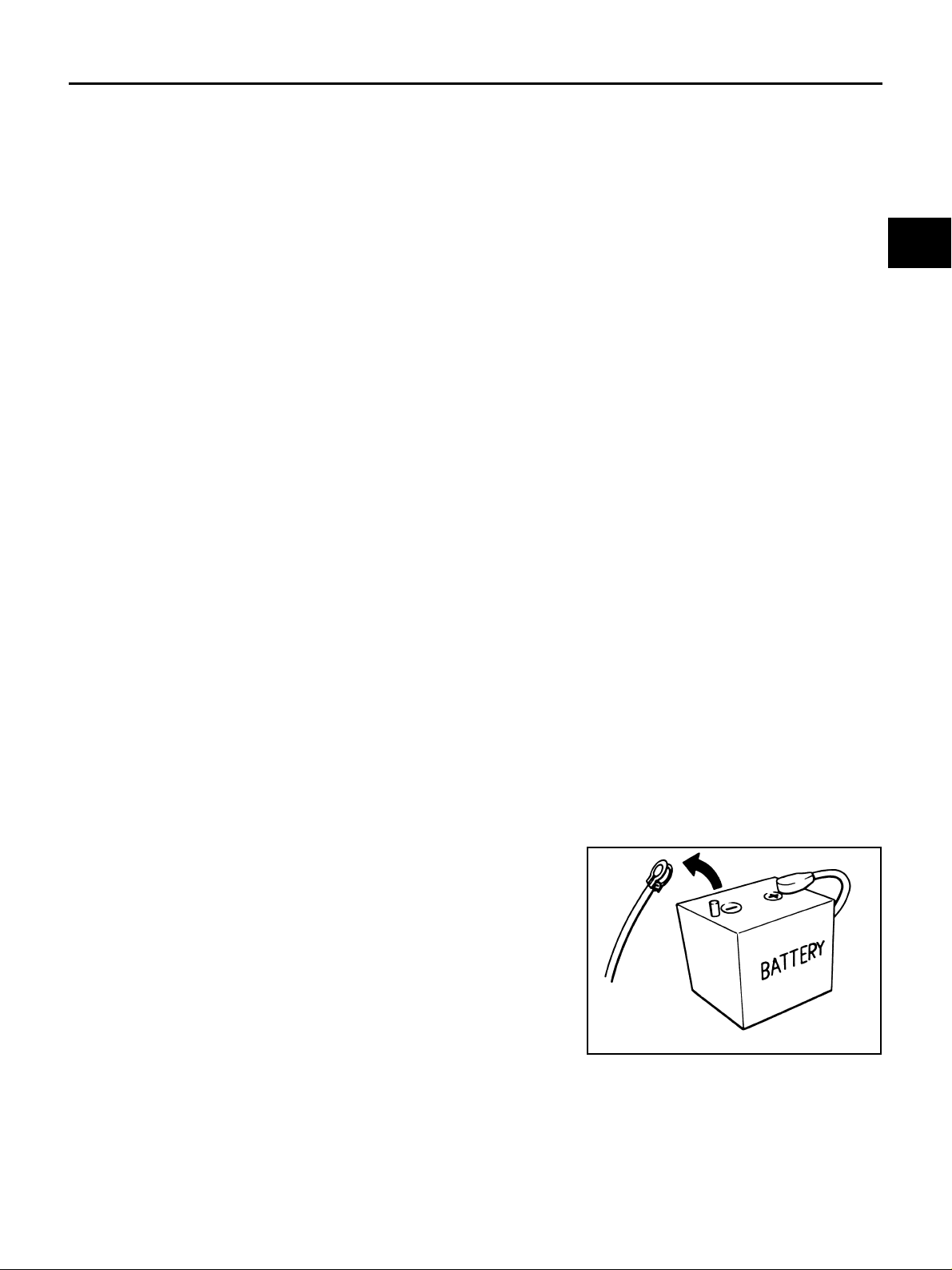
● Be sure to turn the ignition switch OFF a nd disconnect battery negative cable from battery nega-
tive terminal before any repair or inspectio n w ork . The open/s hort c irc uit of re la ted s witches, sensors, solenoid valves, etc. will cause the MIL to light up.
● Be sure to connect and lock the connectors securely after work. A loose (unlocked) connector will
cause the MIL to light up due to an open circuit. (Be sure the connectors are free from water,
grease, dirt, bent terminals, etc.)
● Be sure to route and secure the harnesses properly after work. Interference of the harness with a
bracket, etc. may cause the MIL to light up due to a short circuit.
● Be sure to connect the rubber tub es prope rly after work . A misco nnected or dis conne cted rub ber
tube may cause the MIL to light u p due to a ma lfunction o f the EGR system or fuel inj ection system, etc.
● Be sure to eras e the u nnecess ary mal function i nformatio n (repairs compl eted) from the TC M and
ECM before returning the vehicle to the custom er.
Precautions ACS007QN
B
AT
D
E
F
G
H
I
J
K
L
● Before connecting or dis connecting the TCM harness con-
nector, turn ignition switch OFF and disconnect battery
negative cable from battery negative term inal. Failu re to do
so may damage the TCM. Because battery voltage is
applied to TCM even if ignition switch is turned off.
SEF289H
Revision: 2005 March 2005 X-Trail
AT-7
M

PRECAUTIONS
● When connecting or discon necting pin connectors into or
from TCM, take care not to damage pin term inals (bend or
break).
Make sure that th ere are not any bends or breaks on TCM
pin terminal, when connecting pin connectors.
● Before replacing TCM, perform TCM input/output signal
inspection and make s ure whether TCM fu nctions properly
or not. Refer to AT-77, "
Value" .
TCM Terminals and Reference
AAT470A
MEF040DA
● After performing each TROUBLE DIAGNOSIS, perform
“DTC (Diagnostic Trouble Code) CONFIRMATION PROCEDURE”.
The DTC should not be disp layed in th e “DTC Co nfirmati on
Procedure” if the repair is completed.
● Before proceeding with disassembly, thoroughly clean th e out-
side of the transaxle. It is important to prevent the internal parts
from becoming contaminated by dirt or other foreign matter.
● Disassembly should be done in a clean work area.
● Use lint-free cloth or towels for wiping parts clean. Common
shop rags can leave fibers that could interfere with the operation
SEF217U
of the transaxle.
● Place disassembled parts in order for easier and pro per assembly.
● All parts should be carefully cleaned with a general purpose, non-flammable solvent before inspection or
reassembly.
● Gaskets, seals and O-rings should be replaced any time the transaxle is disassembled.
● It is very important to perform functional tests whenever they are indicated.
● The valve bo dy co ntains precision p a rts and requires extre me ca re w h en p ar t s ar e r em ov ed and s er v ic ed .
Place disassembled valve body parts in order for easier and proper assembly. Care will also prevent
springs and small parts from be coming scattered or lost .
● Properly installed valves, sle ev e s, plugs, etc. will slide along bore s in valve body under their own we ig ht.
● Before assembly, apply a coat of recommended ATF to all parts. Apply petroleum jelly to protect O-rings
and seals, or hold bearings and washers in place during assembly. Do not use grease.
● Extreme care should be taken to avoid damage to O-rings, seals and gaskets when assembling.
● Clean or replace ATF cooler if excessive forei gn mate rial is fo und in oi l pan or clog ging strain er. Refer to
AT-9, "
● After over haul, refill the transaxle with new ATF.
● When the A/T drain plug is remove d, only some of t he fluid is drai ned. O ld A/T flu id wil l remain i n torque
ATF COOLER SERVICE" .
converter and ATF cooling system.
Always follow the procedures under “Changing A/T Fluid” in the AT section when changing A/T fluid. Refer
to “Changing A/T Fluid”, AT-17, "
A/T FLUID" .
Revision: 2005 March 2005 X-Trail
AT-8

PRECAUTIONS
Service Notice or Precautions ACS007QO
ATF COOLER SERVICE
If A/T fluid contains frictional material (clutches, bands, etc.), or if an A/T is repaired, overhauled, or replaced,
inspect and cl ean the A/T oil c ooler mounted in the radiator or replace the radi ator. Flush cooler lines us ing
cleaning solvent and compressed air after repair. Check Service Bulletins for latest A/T oil cooler cleaning procedure. For radiator replacement, refer to CO-11, "
TORQUE CONVERTER SERVICE
The torque converter should be replaced under any of the following conditions:
● External leaks in the hub weld area.
● Converter hub is scored or damaged.
● Converter pilot is broken, damaged or fits poorly into crankshaft.
● Steel particles are found after flushing the cooler and cooler lines.
● Pump is damaged or steel particle s are foun d in the con ve rte r.
● Vehicle has TCC shudder and/or no TCC apply. Replace only after all hydraulic and electrical diagnoses
have been made. (Converter clutch material may be glazed.)
● Converter is contaminated with engine coolant containing antifreeze.
● Internal malfunction of stator roller clutch.
● Heavy clutch debris due to overheating (blue converter).
● Steel particles or clutch lining m a teri al found in fluid filter o r on magnet indicat es th at l in ing m aterial came
from converter when no internal parts in unit are worn or damaged.
The torque converter should not be replaced if:
● The fluid has an odor, is discolored, and there is no evidence of metal or clutch facing particles.
● The threads in one or more of the converter bolt holes are damaged.
● Transaxle malfunction did not display evidence of damaged or worn internal parts, steel particles or clutch
plate lining material in unit and inside the fluid filter.
● Vehicle has been exposed to high mileage (only). The exception may be where the torque converter
clutch damp er plate lining has seen excess wear by vehicles ope rated in heavy and/ or constant traffic,
such as taxi, delivery or police use.
RADIATOR" , CO-14, "RADIAT OR (ALUMINUM TYPE)" .
A
B
AT
D
E
F
G
H
I
J
OBD-II SELF-DIAGNOSIS
● A/T self-diagnosis is performed by the TCM in combination with the ECM. The results can be read through
the blinking pattern of the O/D OFF indicator lamp or the malfunction indicator lamp (MIL). Refer to the
table on AT-8 2 , "
nostic result.
● The self-diagnostic results indicated by the MIL are automatically stored in both the ECM and TCM mem-
ories.
Always perform the procedure “HOW TO ERASE DTC” on AT-40, "
plete the repair and avoid unnecessary blinking of the MIL.
● The following self-diagnostic items can be detected using ECM self-diagnostic results mode* only when
the O/D OFF indicator lamp does not indicate any malfunctions.
– PNP switch
– A/T 1st, 2nd, 3rd, or 4th gear function
*: For details of OBD-II, refer to AT-39, "
● Certain systems and components, especially those related to OBD, may use a new style slide-
locking type harness con nec tor.
For description and how to dis c onnect, refer to PG-44, "
SELF-DIAGNOSTIC RESULT MODE" for the indicator used to display each self-diag-
HOW TO ERASE DTC" to com-
ON BOARD DIAGNOSTIC (OBD) SYSTEM" .
HARNESS CONNECTOR" .
K
L
M
Revision: 2005 March 2005 X-Trail
AT-9

PRECAUTIONS
Wiring Diagrams and Trouble Diagnosis ACS007QP
When reading wiring diag ram s, refer to the foll owin g:
● GI-14, "How to Read Wiring Diagrams"
● PG-2, "POWER SUPPLY ROUTING"
When performing troubl e dia gn os is, refer to the following:
● GI-10, "How to Follow Trouble Diagnoses"
● GI-26, "How to Perform Efficient Diagnosis for an Electrical Incident"
Revision: 2005 March 2005 X-Trail
AT-10
PREPARATION
PREPARATION PFP:00100
Special Service Tools ACS007QQ
The actual shapes of Kent-Moore tools may differ from those of spec ial ser vi ce tool s illust rat ed here.
Tool number
(Kent-Moore No.)
Tool name
Description
A
B
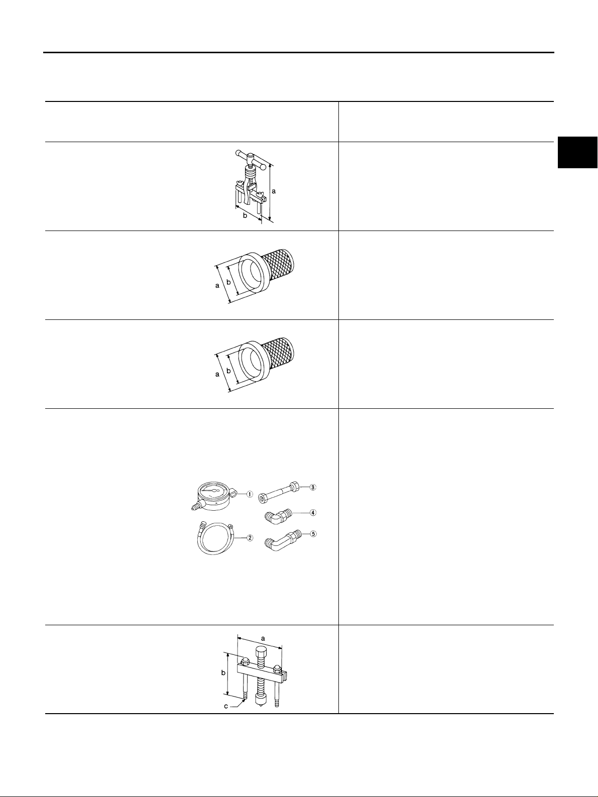
KV381054S0
(J-34286)
Puller
ST33400001
(J-26082)
Drift
KV40100621
(J-25273)
Drift
ST2505S001
(J-34301)
Oil pressure gauge set
1. ST25051001
(J-34301)
Oil pressure gauge
2.ST25052000
(J-34301)
Hose
3.ST25053000
(J-25695-3)
Joint pipe
4.ST25054000
(J-25695-4)
Adapter
5.ST25055000
(J-25695-5)
Adapter
ST27180001
(J-25726-A)
Puller
NT414
NT086
NT086
NT097
● Removing dif ferential sid e bearing outer race
● Removing idler gear bearing outer race
a: 250 mm (9.84 in)
b: 160 mm (6.30 in)
● Installing differential side oil seal
● Installing oil pump housing oil seal
a: 60 mm (2.36 in) dia.
b: 47 mm (1.85 in) dia.
Instal l ing differential side oil seal (With AWD models)
a: 60 mm (2.36 in) dia.
b: 47 mm (1.85 in) dia.
Measuring line pressure
Removing idler gear
a: 100 mm (3.94 in)
b: 110 mm (4.33 in)
c: M8 x 1.25P
AT
D
E
F
G
H
I
J
K
L
M
NT424
Revision: 2005 March 2005 X-Trail
AT-11
Tool number
(Kent-Moore No.)
Tool name
PREPARATION
Description
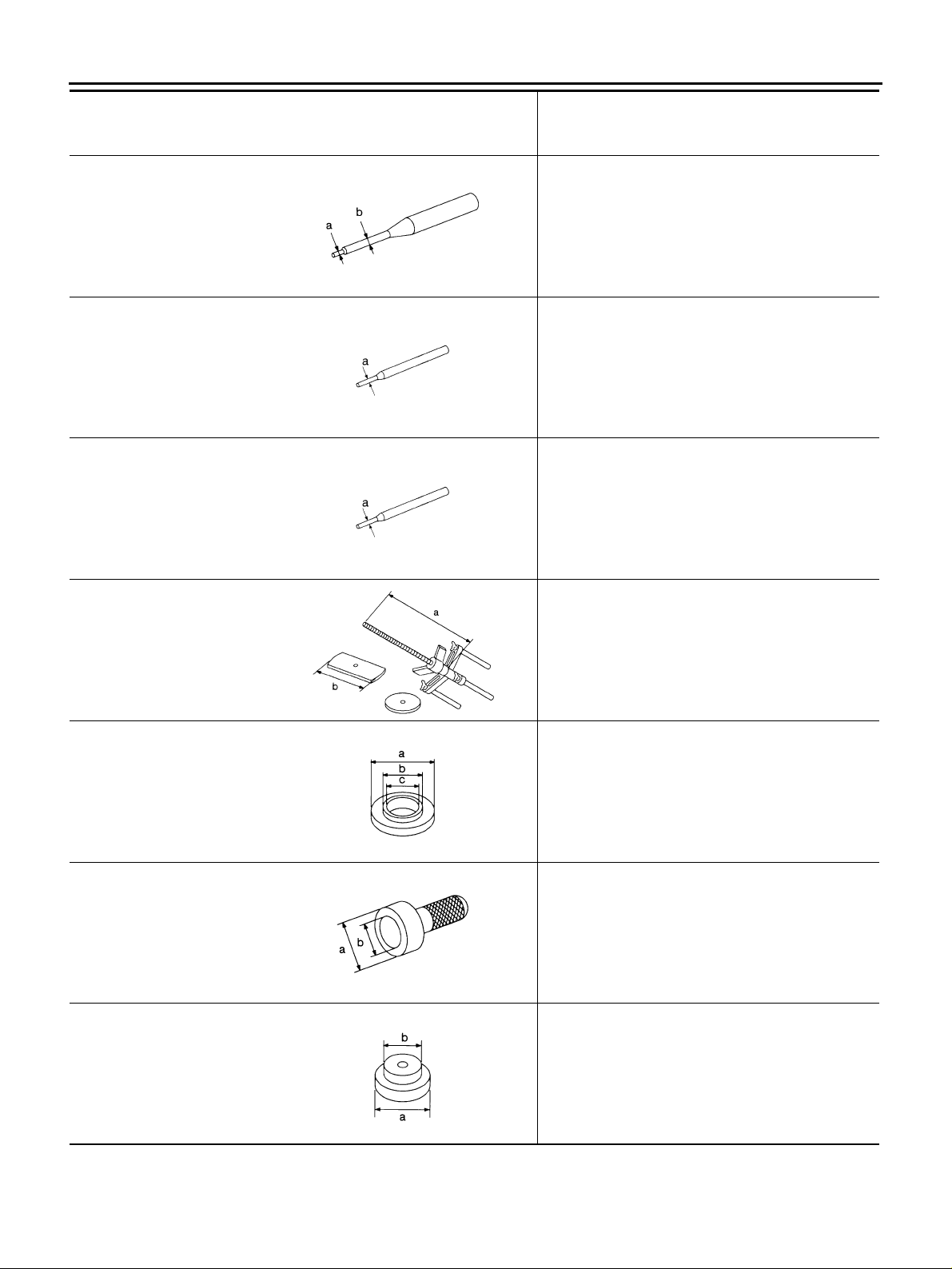
ST23540000
(J-25689-A)
Pin punch
ST25710000
(J-25689-A)
Pin punch
KV32101000
(J-25689-A)
Pin punch
KV31102400
(J-34285)
Clutch spring compressor
Removing and installing parking rod plate and
manual plate retaining pins
a: 2.3 mm (0.091 in) dia.
b: 4 mm (0.16 in) dia.
NT442
Aligning groove of manual shaft and hole of
transaxle case
a: 2 mm (0.08 in) dia.
NT410
● Installing manual shaft retaining pin
● Removing and i nstalling pinion m at e shaf t lock pin
a: 4 mm (0.16 in) dia.
NT410
Removing and installing clutch return springs
a: 320 mm (12.60 in)
b: 174 mm (6.85 in)
KV40100630
(J-26092)
Drift
ST30720000
(J-25405)
Bearing installer
ST35321000
(—)
Drift
NT423
● Installing reduction pinion gear bearing inner race
● Installing idler gear bearing inner race
a: 67.5 mm (2.657 in) dia.
b: 44 mm (1.73 in) dia.
c: 38.5 mm (1.516 in) dia.
NT107
Installing idler gear bearing outer race
a: 77 mm (3.03 in) dia.
b: 55.5 mm (2.185 in) dia.
NT115
Installing output shaft bearing
a: 49 mm (1.93 in) dia.
b: 41 mm (1.61 in) dia.
NT073
Revision: 2005 March 2005 X-Trail
AT-12
PREPARATION
Tool number
(Kent-Moore No.)
Tool name
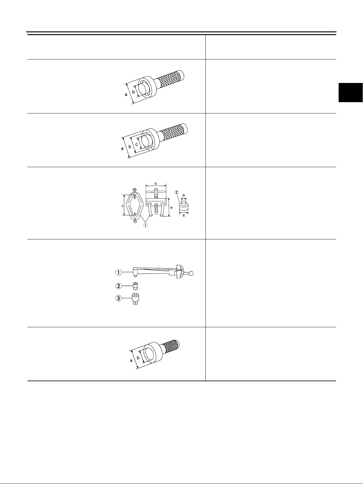
ST33230000
(J-25805-01)
Drift
ST33220000
(—)
Drift
ST3306S001
(J-22888-D)
Differential side bearing
puller set
1.ST33051001
(J-22888-D)
Puller
2.ST33061000
(J-8107-2)
Adapter
ST3127S000
(J-25765-A)
Preload gauge
1.GG91030000
(J-25765-A)
Torque wrench
2.HT62940000
(—)
Socket adapter
3.HT62900000
(—)
Socket adapter
ST35271000
(J-26091)
Drift
NT084
NT085
AMT153
NT124
Description
Installing differential side bearing inner race
a: 51 mm (2.01 in) dia.
b: 28.5 mm (1.122 in) dia.
Selecting differential side bearing adjusting shim
a: 37 mm (1.46 in) dia.
b: 31 mm (1.22 in) dia.
c: 22 mm (0.87 in) dia.
Removing differentia l side bearing inne r race
a: 38 mm (1.50 in) dia.
b: 28.5 mm (1.122 in) dia.
c: 130 mm (5.12 in)
d: 135 mm (5.31 in)
e: 100 mm (3.94 in)
● Checking fina l drive assembly turning torque
● Checking reduct i on pi nion gear tur ning t orque
Installing idler gear
a: 72 mm (2.83 in) dia.
b: 63 mm (2.48 in) dia.
A
B
AT
D
E
F
G
H
I
J
K
L
M
NT115
Revision: 2005 March 2005 X-Trail
AT-13

Tool number
(Kent-Moore No.)
Tool name
PREPARATION
Description
KV38107700
(J-39713)
Preload adapter
KV38105210
(J-39883)
Preload adapter
Selecting differential side beari ng adjus ti ng shim
NT087
● Selecting differential si de bearing adjust ing shim
● Checking fluid drive assembly turning torque
NT075
Revision: 2005 March 2005 X-Trail
AT-14

PREPARATION
Commercial Service Tools ACS007QR
Tool name Description
Power tool Loosening bolts and nuts
PBIC0190E
Puller Removing idler gear bearing inner race
NT077
Puller Removing reduction pinion gear bearing inner
race
a: 60 mm (2.36 in) dia.
b: 35 mm (1.38 in) dia.
A
B
AT
D
E
F
G
NT411
Drift Installing radial needle bearing on bearing
retainer
a: 36 mm (1.42 in) dia.
NT083
Drift Installing manual shaft oil seal
a: 22 mm (0.87 in) dia.
NT083
Drift Removing radial needle bearing from bearing
retainer
a: 33.5 mm (1.319 in) dia.
NT083
H
I
J
K
L
M
Revision: 2005 March 2005 X-Trail
AT-15

PREPARATION
Tool name Description
Drift Installing differential side bearing outer race
(RH side)
a: 75 mm (2.95 in) dia.
NT083
Drift Installing differential side bearing outer race
(LH side)
a: 100 mm (3.94 in) dia.
NT083
Revision: 2005 March 2005 X-Trail
AT-16

A/T FLUID
A/T FLUID PFP:KLE40
Checking A/T Fluid ACS007QS
1. Warm up engine.
2. Check for A/T fluid leakage.
3. Before driving, A/T fluid level can be checked at A/T fluid temperatures of 30 to 50°C (86 to 122°F) using “COLD” range on A/
T fluid level gauge.
a. Park vehicle on level surface and set parking brake.
b. Start engine and move selector lever through each gear posi-
tion. Leave sel ector lever in “P” position.
c. Check A/T fluid level with engine idling.
SMA827CA
d. Remove A /T f lui d level gauge and note reading. If l ev el is a t lo w
side of either range, and A/T fluid to the A/T fluid charging pipe.
CAUTION:
When wiping away the A/T fluid level gauge, always use
lint-free paper, not a cloth one.
e. Re-insert A/T fluid level gauge into A/T fluid charging pipe as far
as it will go.
CAUTION:
Firmly fix the A/T fluid level gau ge to the A/T fluid chargin g
pipe using a stopper attached.
f. Remove A/T fluid level gauge and note reading. If reading is at
low side of range, add A/T fluid to the A /T fluid charging pipe.
CAUTION:
Do not overfill.
4. Drive vehicle f or approximately 5 minutes in urban areas.
5. Recheck A/T fluid level at A/T fluid temperatures of 50 to 80°C (122 to 176°F) using “HOT” range on A/T
fluid level gauge.
CAUTION:
● When wiping away the A/T fluid level gauge, always use lint-free paper, not a cloth one.
● Firmly fix the A/T fluid level gauge to the A/T fluid charging pipe using a stopper attached.
6. Check A/T fluid condition.
● If A/T fluid is very dark or sm ells burned, ch ecking operation
of A/T. Flush cooling system after repair of A/T.
● If A/T fluid contai ns frictional ma terial (clutches, bands, etc. ),
replace radiato r and flush cooler line using cl eaning solvent
and compressed air after repair of A/T. Refer to CO-11,
"RADIATOR" , CO-14, "RADIATOR (ALUMINUM TYPE)" .
7. Install th e remov ed A/ T flui d lev el ga uge in the A /T flu id ch argin g
pipe.
CAUTION:
Firmly fix the A/T fluid level gau ge to the A/T fluid chargin g
pipe using a stopper attached.
SMA051D
SAT638A
A
B
AT
D
E
F
G
H
I
J
K
L
M
Revision: 2005 March 2005 X-Trail
AT-17

A/T FLUID
Changing A/T Fluid ACS007QT
1. Warm up A/T fluid.
2. S top engine.
3. Drain A/T fluid from drain plug and refill with new A/T fluid.
Always refill same volume with drained fluid.
CAUTION:
Do not reuse drain plug gasket.
Fluid grade:
NISSAN Automatic Transmission Fluid (ATF),
TM
DEXRON
Refer to MA-11, "
LUBRICANTS" .
Fluid capacity (With torque converter):
Approx. 8.5 (9 US qt, 7-1/2 lmp qt)
Drain plug
4. Run engine at idle speed for 5 minutes .
5. Check A/T fluid level and condition. Refer to AT- 17, "
steps 2 through 5.
III/MERCONTM , or equivalent ATF.
RECOMMENDED FLUIDS AND
:34 N·m (3.5 kg-m, 25 ft-lb)
SMA027D
Checking A/T Fl uid" . If A/T fluid is still dirty, repeat
A/T Fluid Cooler Cleaning ACS008HQ
Whenever an a utomatic transaxle is repaired , overhauled, or replaced, the A/T fluid cooler mounted i n the
radiator must be inspected and cleaned.
Metal debris and f ric tion mate rial, i f pr ese nt, c an be com e trap ped in the A /T flu id cool er. This debris c an c ontaminate the newly servi ced A/T or, in severe cases, can blo ck or restrict the flow of A/T fluid. In either case,
malfunction of the newly serviced A/T may result.
Debris, if present, may build up as A/T fluid enters the cooler inlet. It will be necessary to back flush the cooler
through the cooler outlet in order to flush out any built up debris.
A/T FLUID COOLER CLEANING PROCEDURE
1. Position an oil pan under the automatic transaxle's inlet and outlet cooler hose s.
2. Identify the inlet and outlet fluid cooler hoses.
3. Disconne ct the flui d co oler i nlet a nd ou tle t rubb er h oses from t he
steel cooler tubes or bypass valve.
NOTE:
Replace the cooler hoses if rubber material from the hose
remains on the tube fitting.
4. Allow any A/T fl uid that remains in the cooler ho ses to drain int o
the oil pan.
SCIA5628E
Revision: 2005 March 2005 X-Trail
AT-18

A/T FLUID
5. Insert the extension adapter hose of a can of Transmission
Cooler Cleaner (Nissan P/N 99 9MP-AM00 6) into the coole r outlet hose.
CAUTION:
● Wear safety glasses and rubber gloves when spraying
the Transmission Cooler Cleaner .
● Spray cooler cleaner only with ad equ ate venti lation.
● Avoid contact with eyes and skin.
● Do not breat h vapors or spray mis t.
6. Hold the hose and can as high as possible and spray Transmission Cooler Cleaner in a continuous stream into the cooler outlet
hose until fluid flows out of the cooler inlet hose for 5 seconds.
7. Insert the tip of an air gun into the end of the cooler outlet hose .
8. Wrap a shop rag around th e air gun tip and of the cooler outle t
hose.
A
B
AT
SCIA5629E
D
E
F
G
SCIA5630E
9. Blow compressed air regulated to 5 - 9 kg/cm
2
(70 - 130 psi) through the cooler outlet ho se for 10 sec-
onds to force out any remaining fluid.
10. Repeat steps 5 through 9 t hree additional times.
11. Position an oil pan under the banjo bolts that connect the fluid cooler steel lines to the transaxle.
12. Remove the banjo bolts.
13. Flush each steel li ne from the cooler side back tow ard the transaxle by spraying Transmiss ion Cooler
Cleaner in a continuous stream for 5 seconds.
2
14. Blow compressed air regulated to 5 - 9 kg/cm
(70 - 130 psi) through each steel line from the c oo ler s id e
back toward the transaxle for 10 seconds to force out any remaining fluid.
15. Ensure all debris is removed from the steel cooler lines.
16. Ens ure all debris is removed from the banjo bolts and fittings.
17. Perform AT-19, "
A/T FLUID COOLER DIAGNOSIS PROCEDURE" .
A/T FLUID COOLER DIAGNOSIS PROCEDURE
NOTE:
Insufficient cleaning of the cooler inlet hose exterior may lead to inaccurate debris identification.
1. Position an oil pan under the automat ic transaxle's inlet and outlet cooler hoses.
2. Clean the ext erior and tip of the cooler inlet hose.
3. Insert the extension adapter hose of a can of Transmission
Cooler Cleaner (Nissan P/N 99 9MP-AM00 6) into the coole r outlet hose.
CAUTION:
● Wear safety glasses and rubber gloves when spraying
the Transmission Cooler Cleaner .
● Spray cooler cleaner only with ad equ ate venti lation.
● Avoid contact with eyes and skin.
● Do not breat h vapors or spray mis t.
4. Hold the hose and can as high as possible and spray Transmission Cooler Cleaner in a continuous stream into the cooler outlet
hose until fluid flows out of the cooler inlet hose for 5 seconds.
SCIA5629E
H
I
J
K
L
M
Revision: 2005 March 2005 X-Trail
AT-19
A/T FLUID
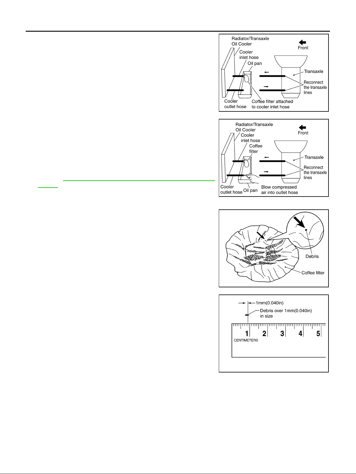
5. Tie a common white, basket-type coffee filter to the end of the
cooler inlet hose.
6. Insert the tip of an air gun into the end of the cooler outlet ho se.
7. Wrap a shop rag around the ai r gun tip and end of co oler outlet
hose.
8. Blow compressed air regulated to 5 - 9 kg/cm
through the cooler outlet hose to force any remaining A/T fluid
into the coffee filter.
9. Remove the coffee filter from the end of the cooler inlet hose.
10. Perform AT-20, "
A/T FLUID COOLER INSPECTION PROCE-
DURE" .
2
(70 - 130 psi)
SCIA5631E
SCIA5632E
A/T FLUID COOLER INSPECTION PROCEDURE
1. Inspect the coffee filter for debris.
a. If small metal debris less than 1mm (0.040 in) in size or metal
powder is found in the coffee filter, this is normal. If normal
debris is found, the A/T f luid co oler/radi ator can be re-u sed an d
the procedu re is ended.
b. If one or more pieces of debris are found that are over 1mm
(0.040 in) in size and/or peeled clutch facing material is found in
the coffee filter, the fluid cooler is not serviceable . The radiator/
fluid cooler must be replaced and the inspection procedure is
ended.
SCIA2967E
SCIA5659E
A/T FLUID COOLER FINAL INSPECTION
After performing all procedures, ensure that all remaining oil is cleaned from all components.
Revision: 2005 March 2005 X-Trail
AT-20

A/T CONTROL SYSTEM
A/T CONTROL SYSTEM PFP:31036
Cross-Sectional View ACS007JH
A
B
AT
D
E
F
G
1. Band servo piston assembly 2. Reverse clutch drum 3. Converter hous ing
4. Oil pump 5. Brake band 6. Reverse clutch
7. High clutch 8. Front planetary gear 9. Low one-way clutch
10. Rear planetary gear 11. Forward clutch 12. Overrun clutch
13. Low & reverse brake 14. Output gear 15. Idler gear
16. Forward one-way clutch 17. Reduc tion pi nion gear 18. Final gear
19. Differential case 20. Input shaft 21. Torque converter
22. Side cover 23. Transaxle case
H
I
J
K
L
M
SCIA4112E
Revision: 2005 March 2005 X-Trail
AT-21

A/T CONTROL SYSTEM
Shift Mechanism ACS007JI
CONSTRUCTION
SAT998I
1. Torque converter 2. Oil pump 3. Input shaft
4. Brake band 5. Reverse clutch 6. High clutch
7. Front sun gear 8. Fr ont pi nion gear 9. Front internal gear
10. Front planetary carrier 11. Rear sun gear 12. Rear pinion gear
13. Rear internal gear 14. Rear planetary carrier 15. Forward clutch
16. Forward one-way clutch 17. Overrun clutch 18. Low one-way clutch
19. Low & reverse brake 20. Parking pawl 21. Parking gear
22. Output shaft 23. Idler gear 24. Output gear
FUNCTION OF CLUTCH AND BRAKE
Clutch and brake components Abbr. Function
5 Reverse clutch R/ C To transmit input power to front sun gear 7 .
6 High clutch H/C To transmit input power to front planetary carrier 10 .
15 Forward clutch F/C To connect front planetary carrier 10 with forward one-way clutch 16 .
17 Overrun clutch O/C To connect front planetary carrier 10 with rear internal gear 13 .
4 Brake band B/B To lock front sun gear 7 .
16 Forward one-way clutch F/O.C
18 Low one-way clutch L/O.C
19 Low & reverse brake L & R/B To lock front planetary carrier 10 .
When forward clutch 15 is engaged, to stop rear internal gear 13 from rotating
in opposite direction against engine revol uti on.
To stop front planetary carrier 10 from rotating in opposite direction against
engine revolution.
Revision: 2005 March 2005 X-Trail
AT-22

CLUTCH AND BAND CHART
Shift posi-
tion
P
R
N
2nd *1A B
D*4
3rd *1A *2C C B
4th C *3C C
2
2nd B
3rd *2C C B
R/C
5
1st *1D B B
1st BB
H/C
6
F/C
15
A/T CONTROL SYSTEM
O/C
17
2nd
apply
Band servo
3rd
release
4th
apply
F/O.C16L/O.C18L&R/B19Lock-
up
*1
Remarks
PARK
POSITION
REVERSE
POSITION
NEUTRAL
POSITION
Automatic
shift
1 ⇔ 2 ⇔ 3
⇔ 4
Automatic
shift
1 ⇔ 2 ⇐ 3
A
B
AT
D
E
F
G
1st BB
1
2nd B
3rd *2C C B
● *1: Operates when overdrive control switch is set in “OFF” posi tion.
● *2: Oil pressure is applied to both 2nd “apply ” side and 3rd “rele ase” side of band s ervo piston. Howe ver, brake band does not con-
tract because oil pressure area on the “release” side is greater than that on the “apply” side.
● *3: Oil pressure is applied to 4th “apply” side in condition *2 above, and brake band contracts.
● *4: A/T will not shift to 4th when overdrive control switch is set in “OFF” position .
● : Operates.
● A: Operates when throttle opening is less than 3/16, activating engine brake.
● B: Operates during “progressive” acceleration.
● C: Operates but does not affect power transmission.
● D: Operates when throttle opening is less than 3/16, but doe s not a ffect engine brake.
Locks (held
stationary)
in 1st speed
1 ⇐ 2 ⇐ 3
H
I
J
K
L
M
Revision: 2005 March 2005 X-Trail
AT-23

A/T CONTROL SYSTEM
POWER TRANSMISSION
“N” and “P” Positions
● “N” position
Power from the input shaft is not transmitted to the output shaft because the clutches do not operate.
● “P” position
Similar to the “N” position, the clutches do not operate. The parking pawl engages with the parking gear to
mechanically hold the output shaft so that the power trai n is locked.
SAT991I
Revision: 2005 March 2005 X-Trail
AT-24
A/T CONTROL SYSTEM
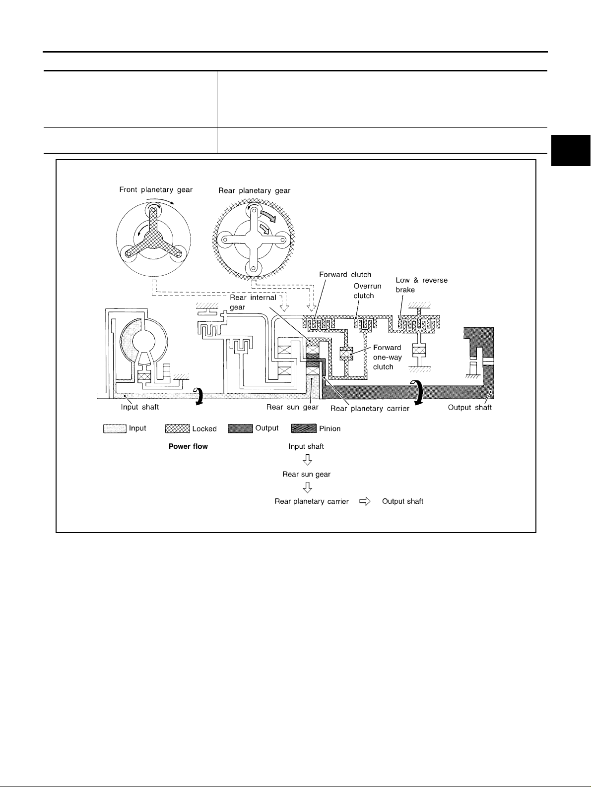
“11 ” Position
● Forward clutch
● Forward one-way clutch
● Overrun clutch
● Low & rever se bra ke
Engine brake Overrun clutch always engages, therefore engine brake can be obtained when deceler-
As overrun clutch engages, rear internal gear is locked by the operation of low and
reverse brake.
This is different from that of D1 and 21 .
ating.
A
B
AT
D
E
F
G
SCIA1816E
H
I
J
K
L
M
Revision: 2005 March 2005 X-Trail
AT-25

“D1 ” and “21 ” Posi t i ons
● Forward one-way clutch
● Forward clutch
● Low one-way clutch
Overrun clutch
engagement conditions
(Engine brake)
A/T CONTROL SYSTEM
Rear internal gear is locked to rotate counterclockwi se bec ause of the functioning of
these three clutches.
D
1 : Overdrive control switch “OFF” and throttle opening i s less tha n 3/16
1 : Always engaged
2
At D
1 and 21 positions, engine brake is not act ivat ed due t o free tu rning of low on e-
way clutch.
SAT377J
Revision: 2005 March 2005 X-Trail
AT-26

“D2 ”, “22 ” and “12 ” Positions
● Forward clutch
● Forward one-way
clutch
● Brake band
Overrun clutch
engagement conditions
Rear sun gear drives rear planetary carrier and combined f ron t interna l gea r. Front internal gear now
rotates around front sun gear accompanying front planetary carrier.
As front planetary carrier transfers the power to rear internal gear through forward clutch and forward oneway clutch, this rotation of rear internal gear increases t he spee d of r ear plan etary carrie r com pared wi th
that of the 1st speed.
2 : Overdrive control switch “OFF” and throttle opening is less tha n 3/1 6
D
2
2 and 12 : Always engaged
A/T CONTROL SYSTEM
A
B
AT
D
E
F
G
SAT378J
H
I
J
K
L
M
Revision: 2005 March 2005 X-Trail
AT-27

“D3 ”, “23 ” and “13 ” Positio n s
● High clutch
● Forward clutch
● Forward one-way
clutch
Overrun clutch
engagement conditions
Input power is transmitted to front planetary carrier throu gh hi gh clut ch. And front pla netary carri er is connected to rear internal gear by operation of forwar d cl ut ch and f orward one-way clutch.
This rear internal gear rotation and another input (the rear sun gear) accompany rear planetary carrier to
turn at the same speed.
3 : Overdrive control switch “OFF” and throttle opening is less than 3/16
D
3 and 13 : Always engaged
2
A/T CONTROL SYSTEM
SCIA7229E
Revision: 2005 March 2005 X-Trail
AT-28

“D4 ” (OD) Position
● High clutch
● Brake band
● Forward clutch (Does not affect power
transmission)
Engine brake
A/T CONTROL SYSTEM
Input power is transmitted to front carrier through high clutch.
This front carrier turns around the sun gear which is fixe d by bra ke band and makes
front inte rn al gear (output) turn fa s t e r.
At D
4 position, there is no one-way clutch in the power trans axl e line and engi ne
brake can be obtained when decelerating.
A
B
AT
D
E
F
G
SAT380J
H
I
J
K
L
M
Revision: 2005 March 2005 X-Trail
AT-29

“R” Positi on
● Reverse clutch
● Low & reverse brake
Engine brake
A/T CONTROL SYSTEM
Front planetary carrier is stationary because of the operation of low and reverse brake.
Input power is transmitted to front sun gear through re ver se cl ut ch, which drives front
internal gear in the opposite direction.
As there is no one-way clutch in the power transaxle line, engi ne bra ke can be
obtained when decelerating.
SAT381J
Revision: 2005 March 2005 X-Trail
AT-30
Loading...