


B ENGINE
SECTION
ENGINE MECHANICAL
CONTENTS
A
EM
C
D
E
KA24DE |
|
PRECAUTIONS ......................................................... |
5 |
Precautions for Drain Coolant ................................. |
5 |
Precautions for Disconnecting Fuel Piping ............. |
5 |
Precautions for Removal and Disassembly ............ |
5 |
Precautions for Inspection, Repair and Replace- |
|
ment ........................................................................ |
5 |
Precautions for Assembly and Installation .............. |
5 |
Parts Requiring Angular Tightening ........................ |
5 |
Precautions for Liquid Gasket ................................. |
6 |
REMOVAL OF LIQUID GASKET SEALING ......... |
6 |
LIQUID GASKET APPLICATION PROCEDURE..... |
6 |
PREPARATION .......................................................... |
7 |
Special Service Tools .............................................. |
7 |
Commercial Service Tools ....................................... |
8 |
NOISE, VIBRATION, AND HARSHNESS (NVH) |
|
TROUBLESHOOTING ............................................. |
10 |
NVH Troubleshooting —Engine Noise ................ ... |
10 |
Use the Chart Below to Help You Find the Cause |
|
of the Symptom. ..................................................... |
11 |
ENGINE ROOM COVER ......................................... |
12 |
Removal and Installation of Engine Room Right |
|
Side ....................................................................... |
12 |
REMOVAL .......................................................... |
12 |
INSTALLTION .................................................... |
12 |
Removal and Installation of Engine Room Rear |
|
Cover ..................................................................... |
12 |
REMOVAL .......................................................... |
12 |
INSTALLATION .................................................. |
13 |
DRIVE BELTS .......................................................... |
14 |
Checking Drive Belts ............................................. |
14 |
Tension Adjustment ............................................... |
14 |
POWER STEERING PUMP BELT ..................... |
14 |
AIR CONDITIONER COMPRESSOR BELT ...... |
14 |
ALTERNATOR AND WATER PUMP BELT ........ |
15 |
Removal and Installation ....................................... |
15 |
REMOVAL .......................................................... |
15 |
INSTALLATION .................................................. |
15 |
AIR CLEANER AND AIR DUCT .............................. |
16 |
Removal and Installation ....................................... |
16 |
REMOVAL .......................................................... |
16 |
INSTALLATION .................................................. |
17 |
Changing Air Cleaner Element .............................. |
18 |
REMOVAL .......................................................... |
18 |
INSTALLATION .................................................. |
18 |
THROTTLE BODY ................................................... |
19 |
Removal and Installation ....................................... |
19 |
REMOVAL .......................................................... |
19 |
INSPECTION AFTER REMOVAL ...................... |
20 |
INSTALLATION .................................................. |
20 |
Disassembly and Assembly ................................... |
20 |
DISASSEMBLY .................................................. |
20 |
ASSEMBLY ........................................................ |
20 |
INTAKE MANIFOLD ................................................ |
21 |
Removal and Installation ....................................... |
21 |
REMOVAL .......................................................... |
21 |
INSPECTION AFTER REMOVAL ...................... |
22 |
INSTALLATION .................................................. |
22 |
EXHAUST MANIFOLD ............................................ |
23 |
Removal and Installation ....................................... |
23 |
REMOVAL .......................................................... |
23 |
INSPECTION AFTER REMOVAL ...................... |
24 |
INSTALLATION .................................................. |
24 |
INSPECTION AFTER INSTALLATION ............... |
24 |
OIL PAN AND OIL STRAINER ................................ |
25 |
Removal and Installation ....................................... |
25 |
REMOVAL .......................................................... |
25 |
INSPECTION AFTER REMOVAL ...................... |
25 |
INSTALLATION .................................................. |
25 |
INSPECTION AFTER INSTALLATION ............... |
26 |
SPARK PLUG (CONVENTIONAL) .......................... |
27 |
Removal and Installation ....................................... |
27 |
REMOVAL .......................................................... |
27 |
INSPECTION AFTER REMOVAL ...................... |
27 |
INSTALLATION .................................................. |
27 |
FUEL INJECTOR AND FUEL TUBE ....................... |
28 |
Removal and Installation ....................................... |
28 |
REMOVAL .......................................................... |
28 |
INSTALLATION .................................................. |
29 |
INSPECTION AFTER INSTALLATION ............... |
29 |
F
G
H
I
J
K
L
M
EM-1

ROCKER COVER .................................................... |
30 |
Removal and Installation ....................................... |
30 |
REMOVAL .......................................................... |
30 |
INSTALLATION ................................................... |
30 |
CAMSHAFT .............................................................. |
32 |
Removal and Installation ....................................... |
32 |
REMOVAL .......................................................... |
32 |
INSTALLATION ................................................... |
34 |
INSPECTION AFTER REMOVAL ....................... |
35 |
Valve Clearance ..................................................... |
38 |
INSPECTION ...................................................... |
38 |
ADJUSTMENT ................................................... |
38 |
SECONDARY TIMING CHAIN ................................. |
41 |
Removal and Installation ....................................... |
41 |
REMOVAL .......................................................... |
41 |
INSPECTION AFTER REMOVAL ....................... |
44 |
INSTALLATION ................................................... |
45 |
PRIMARY TIMING CHAIN ....................................... |
49 |
Removal and Installation ....................................... |
49 |
REMOVAL .......................................................... |
50 |
INSPECTION AFTER REMOVAL ....................... |
51 |
INSTALLATION ................................................... |
51 |
CYLINDER HEAD .................................................... |
55 |
On-Vehicle Service ................................................ |
55 |
CHECKING COMPRESSION PRESSURE ........ |
55 |
Removal and Installation ....................................... |
56 |
REMOVAL AND INSTALLATION ........................ |
56 |
Disassembly and Assembly ................................... |
57 |
DISASSEMBLY .................................................. |
57 |
ASSEMBLY ........................................................ |
58 |
INSPECTION AFTER DISASSEMBLY ............... |
58 |
ENGINE ASSEMBLY ............................................... |
63 |
Removal and Installation ....................................... |
63 |
REMOVAL .......................................................... |
64 |
INSTALLATION ................................................... |
65 |
INSPECTION AFTER INSTALLATION ............... |
66 |
CYLINDER BLOCK .................................................. |
67 |
Disassembly and Assembly ................................... |
67 |
DISASSEMBLY .................................................. |
68 |
ASSEMBLY ........................................................ |
70 |
How to Select Piston and Bearing ......................... |
74 |
DESCRIPTION ................................................... |
74 |
HOW TO SELECT PISTON ................................ |
75 |
HOW TO SELECT CONNECTING ROD BEAR- |
|
ING ..................................................................... |
75 |
HOW TO SELECT MAIN BEARING ................... |
76 |
Inspection After Disassembly ................................ |
78 |
CRANKSHAFT SIDE CLEARANCE ................... |
78 |
CONNECTING ROD SIDE CLEARANCE .......... |
78 |
PISTON AND PISTON PIN CLEARANCE ......... |
78 |
PISTON RING SIDE CLEARANCE .................... |
79 |
PISTON RING END GAP ................................... |
79 |
CONNECTING ROD BEND AND TORSION ...... |
80 |
CONNECTING ROD BEARING (BIG END) ....... |
80 |
CONNECTING ROD BUSHING OIL CLEAR- |
|
ANCE (SMALL END) .......................................... |
80 |
CYLINDER BLOCK DISTORTION ..................... |
81 |
INNER DIAMETER OF MAIN BEARING HOUS- |
|
ING ...................................................................... |
81 |
PISTON TO CYLINDER BORE CLEARANCE ...82 |
|
OUTER DIAMETER OF CRANKSHAFT JOUR- |
|
NAL ..................................................................... |
83 |
OUTER DIAMETER OF CRANKSHAFT PIN .....83 |
|
OUT-OF-ROUND AND TAPER OF CRANK- |
|
SHAFT ................................................................ |
83 |
CRANKSHAFT RUNOUT ................................... |
83 |
OIL CLEARANCE OF CONNECTING ROD |
|
BEARING ............................................................ |
84 |
OIL CLEARANCE OF MAIN BEARING .............. |
84 |
CRUSH HEIGHT OF MAIN BEARING ............... |
85 |
OIL JET ............................................................... |
85 |
OIL JET RELIEF VALVE ..................................... |
85 |
FLY WHEEL RUNOUT ....................................... |
86 |
SERVICE DATA AND SPECIFICATIONS (SDS) .....87 |
|
Standard and Limit ................................................. |
87 |
GENERAL SPECIFICATIONS ............................ |
87 |
DRIVE BELTS ..................................................... |
87 |
INTAKE MANIFOLD AND EXHAUST MANI- |
|
FOLD .................................................................. |
87 |
SPARK PLUG ..................................................... |
88 |
SECONDARY TIMING CHAIN ........................... |
88 |
CYLINDER HEAD ............................................... |
88 |
VALVE ................................................................. |
88 |
CAMSHAFT AND CAMSHAFT BEARING .......... |
92 |
CYLINDER BLOCK ............................................. |
92 |
PISTON, PISTON RING AND PISTON PIN ....... |
93 |
CONNECTING ROD ........................................... |
94 |
CRANKSHAFT .................................................... |
94 |
MAIN BEARING .................................................. |
95 |
CONNECTING ROD BEARING .......................... |
95 |
FLYWHEEL ......................................................... |
96 |
Tightening Torque .................................................. |
96 |
ZD30DD |
|
PRECAUTIONS ........................................................ |
98 |
Precautions for Drain Coolant ................................ |
98 |
Precautions for Disconnecting Fuel Piping ............ |
98 |
Precautions for Removal and Disassembly ........... |
98 |
Precautions for Inspection, Repair and Replace- |
|
ment ....................................................................... |
98 |
Precautions for Assembly and Installation ............. |
98 |
Parts Requiring Angular Tightening ....................... |
98 |
Precautions for Liquid Gasket ................................ |
99 |
REMOVAL OF LIQUID GASKET SEALING ....... |
99 |
LIQUID GASKET APPLICATION PROCEDURE... |
99 |
PREPARATION ...................................................... |
100 |
Special Service Tools ........................................... |
100 |
Commercial Service Tools ................................... |
102 |
NOISE, VIBRATION, AND HARSHNESS (NVH) |
|
TROUBLESHOOTING ........................................... |
103 |
NVH Troubleshooting —Engine Noise ................. . |
103 |
Use the Chart Below to Help You Find the Cause |
|
of the Symptom. ................................................... |
104 |
ENGINE ROOM COVER ........................................ |
105 |
Removal and Installation of Engine Room Right |
|
EM-2

Side ..................................................................... |
105 |
REMOVAL ........................................................ |
105 |
INSTALLATION ................................................ |
105 |
Removal and Installation of Engine Room Rear |
|
Cover ................................................................... |
105 |
REMOVAL ........................................................ |
105 |
INSTALLATION ................................................ |
106 |
DRIVE BELTS ........................................................ |
107 |
Checking Drive Belt ............................................. |
107 |
Tension Adjustment ............................................. |
107 |
Removal and Installation ..................................... |
107 |
WATER PUMP, ALTERNATOR AND A/C COM- |
|
PRESSOR BELT .............................................. |
107 |
Drive Belt Auto Tensioner .................................... |
109 |
REMOVAL ........................................................ |
109 |
INSPECTION AFTER REMOVAL .................... |
109 |
INSTALLATION ................................................ |
109 |
Dummy Pulley ..................................................... |
109 |
REMOVAL ........................................................ |
109 |
INSPECTION AFTER REMOVAL .................... |
109 |
INSTALLATION ................................................ |
109 |
AIR CLEANER AND AIR DUCT ............................. |
110 |
Removal and Installation ...................................... |
110 |
REMOVAL ......................................................... |
110 |
INSTALLATION ................................................. |
111 |
Changing Air Cleaner Element ............................. |
112 |
REMOVAL ......................................................... |
112 |
INSTALLATION ................................................. |
112 |
INTAKE MANIFOLD COLLECTOR AND INTAKE |
|
MANIFOLD ............................................................. |
113 |
Removal and Installation ...................................... |
113 |
REMOVAL ......................................................... |
113 |
INSPECTION AFTER REMOVAL ..................... |
115 |
INSTALLATION ................................................. |
115 |
EXHAUST MANIFOLD ........................................... |
117 |
Removal and Installation ...................................... |
117 |
REMOVAL ......................................................... |
117 |
INSPECTION AFTER REMOVAL ..................... |
118 |
INSTALLATION ................................................. |
118 |
INSPECTION AFTER INSTALLATION ............. |
118 |
OIL PAN AND OIL STRAINER ............................... |
119 |
Removal and Installation ...................................... |
119 |
REMOVAL ......................................................... |
119 |
INSTALLATION ................................................ |
120 |
INSPECTION AFTER INSTALLATION ............ |
120 |
GLOW PLUG ......................................................... |
121 |
Removal and Installation ..................................... |
121 |
REMOVAL ........................................................ |
121 |
INSTALLATION ................................................ |
122 |
VACUUM PUMP .................................................... |
123 |
Removal and Installation ..................................... |
123 |
REMOVAL ........................................................ |
123 |
INSTALLATION ................................................ |
123 |
INSPECTION AFTER INSTALLATION ............ |
123 |
INJECTION TUBE AND INJECTION NOZZLE ..... |
125 |
Removal and Installation ..................................... |
125 |
REMOVAL ........................................................ |
125 |
INSPECTION AFTER REMOVAL .................... |
127 |
INSTALLATION ................................................ |
127 |
INSPECTION AFTER INSTALLATION ............. |
128 |
ELECTRONICCONTROLFUELINJECTIONPUMP. 129 |
|
Removal and Installation ..................................... |
129 |
REMOVAL ........................................................ |
129 |
INSTALLATION ................................................ |
132 |
INSPECTION AFTER INSTALLATION ............. |
134 |
ROCKER COVER .................................................. |
135 |
Removal and Installation ..................................... |
135 |
REMOVAL ........................................................ |
135 |
INSTALLATION ................................................ |
136 |
CAMSHAFT ........................................................... |
138 |
Removal and Installation ..................................... |
138 |
REMOVAL ........................................................ |
139 |
INSPECTION AFTER REMOVAL .................... |
139 |
INSTALLATION ................................................ |
141 |
Valve Clearance .................................................. |
142 |
INSPECTION ................................................... |
142 |
ADJUSTMENTS ............................................... |
144 |
TIMING CHAIN ....................................................... |
147 |
Removal and Installation ..................................... |
147 |
REMOVAL ........................................................ |
147 |
INSPECTION AFTER REMOVAL .................... |
149 |
INSTALLATION ................................................ |
149 |
TIMING GEAR ........................................................ |
151 |
Removal and Installation ..................................... |
151 |
REMOVAL ........................................................ |
152 |
INSPECTION AFTER REMOVAL .................... |
155 |
INSTALLATION ................................................ |
157 |
CYLINDER HEAD .................................................. |
160 |
On-Vehicle Service .............................................. |
160 |
CHECKING COMPRESSION PRESSURE ...... |
160 |
Removal and Installation ..................................... |
161 |
REMOVAL ........................................................ |
161 |
INSPECTION AFTER REMOVAL .................... |
162 |
INSTALLATION ................................................ |
163 |
Disassembly and Assembly ................................. |
166 |
DISASSEMBLY ................................................ |
166 |
ASSEMBLY ...................................................... |
167 |
INSPECTION AFTER DISASSEMBLY ............. |
167 |
ENGINE ASSEMBLY ............................................. |
172 |
Removal and Installation ..................................... |
172 |
REMOVAL ........................................................ |
172 |
INSTALLATION ................................................ |
174 |
INSPECTION AFTER INSTALLATION ............. |
175 |
CYLINDER BLOCK ............................................... |
176 |
Disassembly and Assembly ................................. |
176 |
DISASSEMBLY ................................................ |
177 |
ASSEMBLY ...................................................... |
181 |
How to Select Piston ........................................... |
184 |
DESCRIPTION ................................................. |
184 |
SELECTIVE PISTON COMBINATION ............. |
184 |
INSPECTION AFTER DISASSEMBLY ............. |
185 |
A
EM
C
D
E
F
G
H
I
J
K
L
M
EM-3

SERVICE DATA AND SPECIFICATIONS (SDS) ... 194
Standard and Limit ............................................... |
194 |
GENERAL SPECIFICATIONS .......................... |
194 |
INTAKE MANIFOLD AND EXHAUST MANI- |
|
FOLD ................................................................ |
194 |
DRIVE BELTS .................................................. |
194 |
CYLINDER HEAD ............................................ |
195 |
VALVE ............................................................... |
195 |
CAMSHAFT AND CAMSHAFT BEARING ....... |
199 |
CYLINDER BLOCK ........................................... |
199 |
PISTON, PISTON RING AND PISTON PIN .....200 |
|
CONNECTING ROD ......................................... |
201 |
CRANKSHAFT .................................................. |
201 |
AVAILABLE MAIN BEARING ............................ |
202 |
AVAILABLE CONNECTING ROD BEARING .... |
202 |
MISCELLANEOUS COMPONENTS ................. |
202 |
Tightening torque ................................................. |
203 |
EM-4

PRECAUTIONS
PRECAUTIONS
Precautions for Drain Coolant
●Drain coolant when engine is cooled.
Precautions for Disconnecting Fuel Piping
[KA24DE]
PFP:00001
A
EBS007JS
EM
EBS007JT
●Before starting work, make sure no fire or spark producing items are in the work area.
●Release fuel pressure before disassembly.
●After disconnecting pipes, plug openings to stop fuel leakage.
Precautions for Removal and Disassembly |
EBS007JU |
●When instructed to use special service tools, use the specified tools. Always be careful to work safely, avoid forceful or uninstructed operations.
● Exercise maximum care to avoid damage to mating or sliding surfaces.
● Cover openings of engine system with tape or the equivalent, if necessary, to seal out foreign materials. ● Mark and arrange disassembly parts in an organized way for easy troubleshooting and re-assembly.
● When loosening nuts and bolts, as a basic rule, start with the one furthest outside, then the one diagonally opposite, and so on. If the order of loosening is specified, do exactly as specified.
Precautions for Inspection, Repair and Replacement |
EBS007JV |
●Before repairing or replacing, thoroughly inspect parts. Inspect new replacement parts in the same way, and replace if necessary.
Precautions for Assembly and Installation |
EBS007JW |
C
D
E
F
G
H
●Use torque wrench to tighten bolts or nuts.
●When tightening nuts and bolts, as a basic rule, equally tighten in several different steps starting with the
ones in center, then ones on inside and outside diagonally in this order. If the order of tightening is specified, do exactly as specified.
● Replace with new gasket, packing, oil seal or O-ring.
● Thoroughly wash, clean, and air-blow each part. Carefully check oil or coolant passages for any restriction and blockage.
● Avoid damaging sliding or mating surfaces. Completely remove foreign materials such as cloth lint or dust. Before assembly, oil sliding surfaces well.
●Release air within route after draining coolant.
●After repairing, start engine and increase engine speed to check coolant, fuel, oil, and exhaust systems
for leakage.
Parts Requiring Angular Tightening |
EBS007JX |
●Use an angle wrench for the final tightening of the following engine parts:
– Cylinder head bolts
– Connecting rod cap nuts
●Do not use a torque value for final tightening.
●The torque value for these parts are for a preliminary step.
●Ensure thread and seat surfaces are clean and coated with engine oil.
I
J
K
L
M
EM-5

PRECAUTIONS
[KA24DE]
Precautions for Liquid Gasket |
EBS007JY |
REMOVAL OF LIQUID GASKET SEALING
●After removing the mounting bolts and nuts, disconnect and remove the liquid gasket sealing using a seal cutter.
CAUTION:
Be careful not to damage the mating surfaces.
●In areas where the cutter is difficult to use, use a plastic hammer to lightly tap the areas where the liquid gasket is applied.
CAUTION:
If for some unavoidable reason a tool such as a flat-bladed screwdriver is used, be careful not to damage the mating sur-
faces.
PBIC0275E
LIQUID GASKET APPLICATION PROCEDURE
1.Using a scraper, remove the old liquid gasket adhering to the gasket application surface and the mating surface.
●Remove the liquid gasket completely from the groove of the gasket application surface, mounting bolts, and bolt holes.
2.Wipe the gasket application surface and the mating surface with white gasoline (lighting and heating use) to remove adhering moisture, grease and foreign materials.
3.Attach the liquid gasket to the tube presser.
Use Genuine Liquid Gasket or equivalent.
PBIC0003E
4.Apply the gasket without breaks to the specified location with the specified dimensions.
●If there is a groove for the liquid gasket application, apply the gasket to the groove.
●As for the bolt holes, normally apply the gasket inside the holes. Occasionally, it should be applied outside the holes. Make sure to read the text of service manual.
●Within five minutes of gasket application, install the mating component.
● If the liquid gasket protrudes, wipe it off immediately. |
EMA0622D |
|
●Do not retighten after the installation.
●After 30 minutes or more have passed from the installation, fill the engine oil and coolant.
CAUTION:
If there are specific instructions in the service manual, observe them.
EM-6
|
PREPARATION |
|
|
[KA24DE] |
|
|
|
|
PREPARATION |
PFP:00002 |
|
Special Service Tools |
EBS007JZ |
|
|
|
|
Tool number |
Description |
|
Tool name |
||
|
||
|
|
|
KV10111100 |
Removing steel oil pan and rear timing chain |
|
Seal cutter |
case |
|
ZZA0013D |
|
|
KV10117100 |
Loosening or tightening heated oxygen |
Heated oxygen sensor wrench |
sensors with 22 mm (0.87 in) hexagon nut |
|
ZZA1007D |
|
|
KV10105800 |
Removing and installing idler sproket |
Timing chain stopper |
|
|
ZZA1006D |
|
|
KV101151S0 |
Changing valve lifter shims |
Lifter stopper set |
|
1KV10115120 Lifter stopper
2KV10115110 Camshaft pliers
|
ZZA0103D |
|
|
KV10112100 |
Tightening bolts for bearing cap, cylinder |
Angle wrench |
head, etc. |
|
ZZA0120D |
|
|
|
|
KV10116200 |
|
Disassembling and assembling valve |
|
||
Valve spring compressor |
|
components |
KV10111200 |
|
|
Adapter |
|
|
|
ZZA0993D |
|
|
|
|
|
|
|
KV10116100 |
|
Removing valve oil seal |
Valve oil seal puller |
|
|
ZZA0015D
A
EM
C
D
E
F
G
H
I
J
K
L
M
EM-7

|
PREPARATION |
|
|
[KA24DE] |
|
|
|
|
|
|
|
Tool number |
Description |
|
Tool name |
||
|
||
|
|
|
KV10116300 |
Installing valve oil seal |
|
Valve oil seal drift |
a: 25 mm (0.98 in) dia. |
|
|
b: 14.4 mm (0.567 in) dia. |
|
|
c: 11.8 mm (0.465 in) dia. |
|
|
d: 10 mm (0.39 in) dia. |
|
|
e: 11 mm (0.43 in) |
|
|
f: 9 mm (0.35 in) |
|
|
NT602 |
|
|
|
|
ST0501S000 |
Engine overhaul |
|
Engine stand assembly |
|
ZZA0022D
KV10105001
Engine attachment
|
ZZA1061D |
|
|
ST16610001 |
Removing crankshaft pilot bushing |
Pilot bushing puller |
(M/T model only) |
ZZA0046D
KV10114700
Main bearing cap remover
|
ZZA0023D |
|
|
EM03470000 |
Installing piston assembly into cylinder bore |
Piston ring compressor |
|
|
S-NT044 |
|
|
WS39930000 |
Pressing the tube of liquid gasket |
Tube presser |
|
|
S-NT052 |
|
|
Commercial Service Tools |
EBS007K0 |
EM-8

PREPARATION
[KA24DE]
Tool number
Tool name Description
Quick connector release Removing fuel tube quick connectors in engine room
(Available in SEC. 164 of PARTS
CATALOG: Part No. 16441 6N210)
PBIC0198E
Spark plug wrench |
Removing and installing spark plug |
S-NT047
Valve seat cutter set |
Finishing valve seat dimensions |
S-NT048
Piston ring expander |
Removing and installing piston ring |
|
S-NT030 |
|
|
|
|
Valve guide drift |
|
Removing and installing valve guide |
|
||
|
|
Intake & Exhaust: |
|
|
a: 109.5 mm (0.413 in) dia. |
|
|
b: 6.6 mm (0.260 in) dia. |
|
S-NT015 |
|
|
|
|
|
|
|
Valve guide reamer |
|
1: Reaming valve guide inner hole |
|
||
|
|
2: Reaming hole for oversize valve guide |
|
|
Intake & Exhaust: |
|
|
d1 : 7.0 mm (0.276 in) dia. |
|
|
d2 : 11.175 mm (0.440 in) dia. |
|
S-NT016 |
|
|
|
|
|
|
|
Rear oil seal drift |
|
Installing rear oil seal |
ZZA0025D
A
EM
C
D
E
F
G
H
I
J
K
L
M
EM-9

NOISE, VIBRATION, AND HARSHNESS (NVH) TROUBLESHOOTING
|
[KA24DE] |
NOISE, VIBRATION, AND HARSHNESS (NVH) TROUBLESHOOTING |
PFP:00003 |
NVH Troubleshooting —Engine Noise |
EBS007K1 |
PBIC0192E
EM-10
NOISE, VIBRATION, AND HARSHNESS (NVH) TROUBLESHOOTING
[KA24DE]
Use the Chart Below to Help You Find the Cause of the Symptom. |
EBS007K2 |
1.Locate the area where noise occurs.
2.Confirm the type of noise.
3.Specify the operating condition of engine.
4.Check specified noise source.
If necessary, repair or replace these parts.
|
|
|
|
|
|
Operating condition of engine |
|
|
|
|
||||
Location |
Type of |
|
|
|
|
|
|
|
|
Source of |
|
Refer- |
||
|
Before |
After |
When |
When |
When |
While |
Check item |
|||||||
of noise |
noise |
noise |
ence page |
|||||||||||
warm- |
warm- |
start- |
||||||||||||
|
||||||||||||||
idling |
racing |
driving |
|
|||||||||||
|
|
|
|
|
|
|
||||||||
|
|
|
|
up |
up |
ing |
|
|
|
|||||
|
|
|
|
|
|
|
|
|
|
|||||
|
|
|
|
|
|
|
|
|
|
|
|
|
||
Top of |
Ticking or |
|
C |
A |
— |
A |
B |
— |
Tappet |
Valve clearance |
EM-38 |
|||
engine |
clicking |
|
noise |
|||||||||||
|
|
|
|
|
|
|
|
|
||||||
Rocker |
|
|
|
|
|
|
|
|
|
|
|
|
|
|
|
|
|
|
|
|
|
|
|
|
Camshaft |
Camshaft journal clear- |
|
||
cover |
|
|
|
|
|
|
|
|
|
EM-36 |
||||
Rattle |
|
C |
A |
— |
A |
B |
C |
bearing |
ance |
|||||
Cylinder |
|
|||||||||||||
|
EM-35 |
|||||||||||||
|
|
|
|
|
|
|
|
|
noise |
Camshaft runout |
||||
head |
|
|
|
|
|
|
|
|
|
|||||
|
|
|
|
|
|
|
|
|
|
|||||
|
|
|
|
|
|
|
|
|
|
|
|
|||
|
|
|
|
|
|
|
|
|
|
|
|
|
|
|
|
|
|
|
|
|
|
|
|
|
|
|
Piston and piston pin |
|
|
|
|
Slap or |
— |
A |
— |
B |
B |
— |
Piston pin |
clearance |
EM-80 |
|||
|
|
knock |
noise |
Connecting rod bush- |
EM-80 |
|||||||||
|
|
|
|
|
|
|
|
|
||||||
|
|
|
|
|
|
|
|
|
|
|
|
ing clearance |
|
|
|
|
|
|
|
|
|
|
|
|
|
|
|
|
|
|
|
|
|
|
|
|
|
|
|
|
|
Piston-to-bore clear- |
|
|
Crank- |
|
|
|
|
|
|
|
|
|
|
ance |
EM-80 |
||
|
|
|
|
|
|
|
|
|
|
Piston ring side clear- |
||||
Slap or |
|
|
|
|
|
|
|
Piston |
EM-79 |
|||||
shaft pul- |
|
|
|
|
|
|
|
|||||||
|
A |
— |
— |
B |
B |
A |
ance |
|||||||
rap |
|
slap noise |
EM-79 |
|||||||||||
ley |
|
|||||||||||||
|
|
|
|
|
|
|
Piston ring end gap |
|||||||
|
|
|
|
|
|
|
|
|
|
EM-80 |
||||
Cylinder |
|
|
|
|
|
|
|
|
|
|
||||
|
|
|
|
|
|
|
|
|
|
Connecting rod bend |
||||
|
|
|
|
|
|
|
|
|
|
|
||||
block |
|
|
|
|
|
|
|
|
|
|
|
|||
|
|
|
|
|
|
|
|
|
|
and torsion |
|
|||
(Side of |
|
|
|
|
|
|
|
|
|
|
|
|
||
|
|
|
|
|
|
|
|
|
|
|
|
|
||
|
|
|
|
|
|
|
|
|
|
|
Connecting rod bush- |
|
||
engine) |
|
|
|
|
|
|
|
|
|
Connect- |
|
|||
|
|
|
|
|
|
|
|
|
ing clearance (Small |
|
||||
Oil pan |
|
|
|
|
|
|
|
|
|
|
||||
|
|
|
|
|
|
|
|
|
ing rod |
EM-80 |
||||
Knock |
|
A |
B |
C |
B |
B |
B |
end) |
||||||
|
|
|
||||||||||||
|
|
|
bearing |
EM-80 |
||||||||||
|
|
|
|
|
|
|
|
|
|
|
Connecting rod bear- |
|||
|
|
|
|
|
|
|
|
|
|
|
noise |
|
||
|
|
|
|
|
|
|
|
|
|
|
ing clearance (Big end) |
|
||
|
|
|
|
|
|
|
|
|
|
|
|
|
||
|
|
|
|
|
|
|
|
|
|
|
|
|
|
|
|
|
|
|
|
|
|
|
|
|
|
Main |
Main bearing oil clear- |
EM-84 |
|
|
|
Knock |
|
A |
B |
— |
A |
B |
C |
bearing |
ance |
|||
|
|
|
EM-83 |
|||||||||||
|
|
|
|
|
|
|
|
|
|
|
noise |
Crankshaft runout |
||
|
|
|
|
|
|
|
|
|
|
|
|
|||
|
|
|
|
|
|
|
|
|
|
|
|
|
||
Front of |
|
|
|
|
|
|
|
|
|
Timing |
Timing chain cracks |
|
||
engine |
|
|
|
|
|
|
|
|
|
chain and |
|
|||
Tapping or |
|
|
|
|
|
|
|
and wear |
EM-44 |
|||||
Timing |
|
A |
A |
— |
B |
B |
B |
chain ten- |
||||||
ticking |
|
Timing chain tensioner |
EM-51 |
|||||||||||
chain |
|
|
|
|
|
|
|
sioner |
||||||
|
|
|
|
|
|
|
|
|
operation |
|
||||
cover |
|
|
|
|
|
|
|
|
|
noise |
|
|||
|
|
|
|
|
|
|
|
|
|
|
||||
|
|
|
|
|
|
|
|
|
|
|
|
|
|
|
|
|
|
|
|
|
|
|
|
|
|
Other |
|
|
|
|
|
Squeak- |
|
|
|
|
|
|
|
drive belts |
|
|
||
|
|
ing or fizz- |
|
A |
B |
— |
B |
— |
C |
(Sticking |
Drive belts deflection |
|
||
|
|
ing |
|
|
|
|
|
|
|
or slip- |
|
EM-14 |
||
|
|
|
|
|
|
|
|
|
|
|
ping) |
|
||
|
|
|
|
|
|
|
|
|
|
|
|
|
||
Front of |
|
|
|
|
|
|
|
|
|
|
|
|
|
|
|
|
|
|
|
|
|
|
|
|
Other |
Idler pulley bearing |
|
||
engine |
|
|
|
|
|
|
|
|
|
|
||||
Creaking |
|
A |
B |
A |
B |
A |
B |
drive belts |
|
|||||
|
|
|
operation |
|
||||||||||
|
|
|
|
|
|
|
|
|
|
|
(Slipping) |
|
||
|
|
|
|
|
|
|
|
|
|
|
|
|
||
|
|
|
|
|
|
|
|
|
|
|
|
|
|
|
|
|
Squall |
|
|
|
|
|
|
|
Water |
|
|
||
|
|
|
A |
B |
— |
B |
A |
B |
pump |
Water pump operation |
CO-21 |
|||
|
|
Creak |
|
|||||||||||
|
|
|
|
|
|
|
|
|
noise |
|
|
|||
|
|
|
|
|
|
|
|
|
|
|
|
|
||
|
|
|
|
|
|
|
|
|
|
|
|
|
|
|
A: Closely related B: Related |
C: Sometimes related |
—: Not related |
|
|
|
|
||||||||
A
EM
C
D
E
F
G
H
I
J
K
L
M
EM-11
ENGINE ROOM COVER
|
[KA24DE] |
ENGINE ROOM COVER |
PFP:14049 |
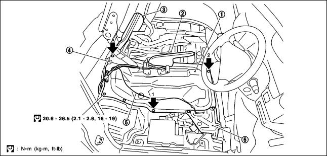
Removal and Installation of Engine Room Right Side |
EBS00ALX |
KBIA0741E
1. |
Engine room right side cover |
2. |
Parking brake lever |
3. |
Engine room left side cover |
4. |
Parking brake cable |
5. |
Harness |
6. |
Harness protector |
REMOVAL
1.Open engine compartment LH cover and secure it.
2.Remove RH seat. Refer to SE-4, "FRONT SEAT" .
3.Partially remove floor carpet.
4.Disconnect harness protector secured together at front right. Disconnect harness connector to move harness routed on top of engine compartment RH cover aside.
5.Move parking brake lever and cable from engine compartment RH cover. Refer to PB-3, "PARKING BRAKE SYSTEM" .
6.Remove mounting bolts, and remove engine compartment RH cover.
CAUTION:
When taking it out of vehicle, do not allow it to interfere with vehicle.
INSTALLTION
●Install in reverse order of removal following instructions below.
1.Temporarily tighten bolt No. 1 shown in the figure.
2.Tighten bolt No. 2 shown in figure to specified torque.
3.Tighten other bolts except bolt “A” shown in the figure (bolt No. 1 is included) to specified torque in any given order.
4.Close engine compartment LH cover.
5.Tighten bolt “A” shown in the figure to specified torque.
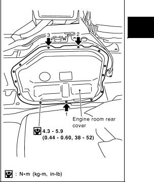
Removal and Installation of Engine Room Rear Cover |
EBS00ALY |
REMOVAL
1.Move folded seat on engine compartment rear cover side rearward, if applicable.
2.Partially remove floor carpet.
3.Remove mounting bolts, and remove engine compartment rear cover.
EM-12
ENGINE ROOM COVER
|
[KA24DE] |
|
INSTALLATION |
|
|
Following instructions below, install in reverse order of removal. |
|
A |
|
||
1.Tighten bolts No. 1 to No. 3 shown in the figure to specified torque in this order.
2. Tighten other bolts to specified torque in any given order. |
EM |
|
C
D
E
F
G
KBIA0742E
H
I
J
K
L
M
EM-13
|
DRIVE BELTS |
|
[KA24DE] |
|
|
DRIVE BELTS |
PFP:02117 |
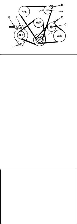
Checking Drive Belts |
EBS007K4 |
WARNING:
Be sure to perform when the engine is stopped.
●Inspection should be done only when engine is cold, or over 30 minutes after engine is stopped.
●Measure belt tension with tension meter (special service tool) at points marked  shown in the figure.
●Measure belt deflection by applying load of 98.1 N {10 kg} to  .
.
PBIC0422E
|
|
|
|
|
Unit: mm (in) |
|
|
|
|
|
|
|
|
|
|
Deflection adjustment |
|
|
|
|
|
|
|
|
|
|
Used belt |
New belt |
|
|
|
|
|
|
|
|
|
Limit |
|
After adjustment |
|
|
|
|
|
|
|
Alternator |
|
11 (0.43) |
|
7 - 8 (0.28 - 0.31) |
6 - 7 (0.24 - 0.28) |
|
|
|
|
|
|
Air conditioner compressor |
|
13 (0.51) |
|
8 - 10 (0.31 - 0.39) |
7 - 8 (0.28 - 0.31) |
|
|
|
|
|
|
Power steering oil pump |
|
13 (0.51) |
|
8 - 10 (0.31 - 0.39) |
7 - 8 (0.28 - 0.31) |
|
|
|
|
|
|
Applied pushing force |
|
|
|
98 N (10 kg, 72 lb) |
|
|
|
|
|
|
|
Tension Adjustment |
|
|
|
EBS00AM2 |
|
CAUTION:
●When belt is replaced with a new one, tighten it a little stronger than current one to accommodate for insufficient adaptability with pulley grooves.
●When tension of belt being used exceeds ″Retightening limit″, adjust it to value for ″Used belt″.
●When installing belt, make sure that it is correctly engaged with pulley groove.
●Keep oil and water away from belt.
●Do not twist or bend belt excessively.
POWER STEERING PUMP BELT
1.Open and fix engine compartment LH cover.
2.Loosen idler pulley lock nut (A) and adjust tension by turning adjusting bolt (B).
●For specified belt tension, refer to EM-14, "Checking Drive Belts" .
3.Tighten nut (A).
 : 25.5 - 32.4 N·m (2.6 - 3.3 kg-m, 19 - 23 ft-lb)
EMK0571D
AIR CONDITIONER COMPRESSOR BELT
1.Open and fix engine compartment LH cover (passenger side for RHD models or driver-side for LHD models).
2.Loosen idler pulley lock nut (C) and adjust tension by turning adjusting bolt (D). ● For specified belt tension, refer to EM-14, "Checking Drive Belts" .
3.Tighten nut (C).
EM-14

DRIVE BELTS
[KA24DE]
 : 25.5 - 32.4 N·m (2.6 - 3.3 kg-m, 19 - 23 ft-lb)
ALTERNATOR AND WATER PUMP BELT
1.Remove front-side under cover.
2.Remove RH seat. Refer to SE-4, "FRONT SEAT" .
3.Remove engine compartment RH cover. Refer to EM-12, "ENGINE ROOM COVER" .
4.Loosen alternator mounting bolt (E) and adjuster lock bolt (F), and adjust tension by turning adjusting nut
(G).
● For specified belt tension, refer to EM-14, "Checking Drive Belts" .
5.Tighten bolts (E), (F) and (G).
: 45.1 - 59.8 N·m (4.6 - 6.1 kg-m, 34 |
- 44 ft-lb) for E bolt |
: 15.7 - 20.6 N·m (1.6 - 2.1 kg-m, 12 |
- 15 ft-lb) for F bolt |
: 6.5 - 7.6 N·m (0.67 - 0.77 kg-m, 58 - 67 in-lb) for G bolt |
|
Removal and Installation |
EBS007K6 |
REMOVAL
A
EM
C
D
E
F
●Loosen each belt while referring to "Adjustment", and remove them one by one starting from the one in front.
INSTALLATION
1.Install belts to pulley in reverse order of removal.
2.Adjust belt tension.
CAUTION:
●When checking belt tension immediately after installation, first, adjust to specified value. Then, after turning crankshaft more than two turns, re-adjust to specified value to avoid variation in deflection between pulleys.
●Tighten idler pulley lock nut by hand and measure tension without looseness.
3.Tighten each adjusting bolt and nut to the specified torque.
4.Make sure that tension of each belt is within the standard.
G
H
I
J
K
L
M
EM-15

AIR CLEANER AND AIR DUCT
|
[KA24DE] |
AIR CLEANER AND AIR DUCT |
PFP:16500 |
Removal and Installation |
EBS007K8 |
KBIA0821E
1 |
PCV hose |
2 |
Air duct |
3 |
Collar |
4 |
Grommet |
5 |
Clamp |
6 |
Collar |
7 |
Grommet |
8 |
Resonator |
9 |
Clamp |
10 |
Resonator |
11 |
Clamp |
12 |
Air hose |
13 |
Resonator |
14 |
Clamp |
15 |
Mass air flow meter |
16 |
Air cleaner case |
17 |
Grommet |
18 |
Air cleaner element |
19 |
Washer |
20 |
Wing nut |
21 |
Seal ring |
22 |
Dust pan |
23 |
Washer |
24 |
Wing nut |
25 |
Dust exhaust valve |
26 |
Grille |
27 |
Screw |
28 |
Air duct |
29 |
Grommet |
30 |
Air duct |
31 |
Resonator |
32 |
Grommet |
33 |
Collar |
34 |
Resonator |
35 |
Clamp |
|
|
REMOVAL
1.Remove rear-side under cover.
2.Open and fix engine room LH cover.
3.Remove RH seat. Refer to SE-4, "FRONT SEAT" .
4.Remove engine room RH cover. Refer to EM-12, "ENGINE ROOM COVER" .
5.Remove floor cover behind RH seat.
6.Disconnect harness connector from airflow sensor.
EM-16

AIR CLEANER AND AIR DUCT
[KA24DE]
7.For correct installation, make matching marks on each connection.
8.Remove from engine side after separating the system with the following procedure.
a.Remove PCV hose (A).
b.Remove air duct (B).
c.Separate air hose (C) and resonator (D).
d.Remove resonator (E).
e.Remove air hose (C).
f.Remove resonator (D).
g.Remove mass air flow sensor (F).
CAUTION:
●Handle with care, avoiding any shocks.
●Do not disassemble it.
●Do not touch sensor part.
h.After removing mud flap of front RH wheel, remove resonator
(G).
i.When removing following parts, remove EVAP canister, and set it aside.
j.Remove resonator (H).
k.Remove air cleaner case (I).
9.When removing components inside vehicle on right-hand, remove them with the following procedure.
a.Remove components up to air cleaner case (I), referring to step 8.
b.Remove intake grille from outside of vehicle.
c.Remove kicking plate on RH side, and lift up panel under RH side seat belt anchor.
d.Lift up air duct (J) from vehicle opening, and separate it from air duct (K).
e.Pull and remove air duct (K).
f.Remove air duct (J) from mounting hole of air duct (K).
INSTALLATION
Install in reverse order of removal, paying attention to points below.
KBIA0822E
KBIA0902E
●After aligning matching marks marked when removing, install each connection, and firmly tighten clamps.
●Install dust drain valve so that its opening is along circumference.
KBIA0819E
A
EM
C
D
E
F
G
H
I
J
K
L
M
EM-17

AIR CLEANER AND AIR DUCT
[KA24DE]
Changing Air Cleaner Element |
EBS0096T |
REMOVAL
NOTE:
●Mark ″*″ in the figure shows part of lift arm.
●For replacement of air cleaner element, it is not necessary to lift up vehicle.
1.Remove brake pipe protector under vehicle, behind front RH wheel.
2.Remove 3 clips, and the cover at the bottom of air cleaner case.
3.Remove wing nut, dust pan under air cleaner case, and then air cleaner element.
KBIA0749E
INSTALLATION
Install in the reverse order of removal.
EM-18

|
|
THROTTLE BODY |
|||
|
|
[KA24DE] |
|||
|
|
|
|
|
|
THROTTLE BODY |
PFP:16298 |
||||
Removal and Installation |
|
|
|
A |
|
EBS008X7 |
|||||
|
|
|
|
|
|
|
|
|
|
|
|
|
|
|
|
|
EM |
|
|
|
|
|
|
|
|
|
|
|
C |
|
|
|
|
|
D |
|
|
|
|
|
E |
|
|
|
|
|
F |
|
|
|
|
|
G |
|
|
|
|
|
H |
|
|
|
|
|
I |
|
|
KBIA0823E |
|
||
|
|
|
|
|
|
1 |
Bracket |
2 |
Throttle position sensor harness |
3 |
Water hose |
4 |
Throttle body |
5 |
Bracket |
6 |
Water hose |
7 |
Gasket |
8 |
Intake manifold |
|
|
REMOVAL
1.Remove RH seat. Refer to SE-4, "FRONT SEAT" .
2.Remove engine compartment RH cover. Refer to EM-12, "ENGINE ROOM COVER" .
3.Remove air duct on throttle body. Refer to EM-16, "AIR CLEANER AND AIR DUCT" .
4.Disconnect accelerator cable, and set it aside.
5.Disconnect harness connector.
6.Disconnect water hose.
● After disconnection, plug the hose to prevent coolant leaks.
7.Loosen mounting bolts in reverse order shown in the figure, and remove throttle body.
J
K
L
M
PBIC0424E
EM-19

THROTTLE BODY
[KA24DE]
INSPECTION AFTER REMOVAL
●If idle is rough when engine is cold or warmed up, check and adjust the fast idle cam (FIC). Refer to EC28, "Fast Idle Cam (FIC) Inspection and Adjustment" .
INSTALLATION
Install in reverse order of removal, paying attention to points below.
●For throttle body, tighten mounting bolts in two steps in the numerical order shown in the figure.
●For adjustment of accelerator cable, refer to ACC-3, "ACCELERATOR CONTROL SYSTEM (KA24DE)" .
 1st step : 8.8 - 10.8 N·m (0.9 - 1.1 kg-m, 78 - 95 in-lb)
 2nd step : 17.7 - 21.6 N·m (1.8 - 2.2 kg-m, 13 - 15 ft-lb)
|
PBIC0424E |
Disassembly and Assembly |
EBS008X8 |
PBIC0425E
1 |
Throttle body |
2 |
Throttle position sensor |
3 |
IACV-FICD solenoid valve |
4 |
Washer |
5 |
Spring |
6 |
plunger |
7 |
Gasket |
8 |
IACV-AAC valve |
|
|
DISASSEMBLY
Disassemble referring to the component illustration.
ASSEMBLY
Assemble in reverse order of disassembly, paying attention to points below.
●Insert throttle position sensor into throttle body, with connectors positioned as shown in the figure. Then rotate it in the direction shown by arrow and temporarily tighten mounting screws.
●While they are turned in direction shown by arrow, circumference of sensor hits projection. Avoid hitting projection by giving slight space, and insert projection into inside of mounting screw long hole. (It is temporarily held in place by counter-action of spring.)
●After adjustment on vehicle, tighten mounting screws.
For adjusting procedure, refer to EC-45, "Basic Inspection" .
PBIC0426E
EM-20
|
|
INTAKE MANIFOLD |
|||
|
|
[KA24DE] |
|||
|
|
|
|
|
|
INTAKE MANIFOLD |
PFP:14003 |
||||
Removal and Installation |
|
|
|
A |
|
EBS007K9 |
|||||
|
|
|
|
|
|
|
|
|
|
|
|
|
|
|
|
|
EM |
|
|
|
|
|
|
|
|
|
|
|
C |
|
|
|
|
|
D |
|
|
|
|
|
E |
|
|
|
|
|
F |
|
|
|
|
|
G |
|
|
|
|
|
H |
|
|
|
|
|
I |
|
|
|
|
|
J |
|
|
|
|
|
K |
|
|
|
|
|
L |
PBIC0427E
M
1 |
Bracket |
2 |
Grounding wire |
3 |
Bracket |
4 |
Vacuum hose |
5 |
Intake manifold |
6 |
Heater pipe |
7 |
Water hose |
8 |
Water hose |
9 |
Intake manifold support |
10 |
Vacuum hose |
11 |
Thermal transmitter |
12 |
Water outlet |
13 |
Gasket |
14 |
Water hose |
15 |
PCV hose |
16 |
Gasket |
17 |
Air relief plug |
18 |
Gasket |
19 |
Engine coolant temperature sensor |
20 |
Gasket |
|
|
REMOVAL
1.Release fuel pressure. Refer to EC-27, "Fuel Pressure Release" .
2.Drain coolant. Refer to CO-9, "ENGINE COOLANT" .
3.Remove RH seat. Refer to SE-4, "FRONT SEAT" .
4.Remove engine compartment RH cover and rear cover. Refer to EM-12, "ENGINE ROOM COVER" .
5.Remove floor cover behind RH seat.
EM-21

INTAKE MANIFOLD
[KA24DE]
6.Move aside main harness above intake manifold.
7.Disconnect PCV hose between rocker cover and air duct.
8.Remove air duct between throttle body and mass air flow sensor. Refer to EM-16, "AIR CLEANER AND AIR DUCT" .
9.Remove throttle body. Refer to EM-19, "THROTTLE BODY" .
10.Remove fuel tube and injector assembly. Refer to EM-28, "FUEL INJECTOR AND FUEL TUBE" .
11.Disconnect radiator hose (upper).
12.Disconnect hoses connected to intake manifold.
NOTE:
Separate water hose and PCV hose behind intake manifold when removing intake manifold.
13.Remove intake manifold with the following procedure.
a.Loosen mounting bolts and nuts in reverse order shown in the figure.
b.Pull out stud bolts on rear.
c.Disconnect water hose and PCV hose on back side, and remove intake manifold.
PBIC0428E
INSPECTION AFTER REMOVAL
Surface Distortion
●Using straightedge and feeler gauge, inspect surface distortion of intake manifold.
Limit |
: 0.1 mm (0.004 in) |
PBIC0429E
INSTALLATION
Assemble in reverse order of removal, paying attention to the following.
Intake Manifold Bolts
●Tighten in numerical order as shown in the figure.
 : 15.7 - 18.6 N·m (1.6 - 1.8 kg-m, 12 - 13 ftlb)
PBIC0428E
Water Outlet
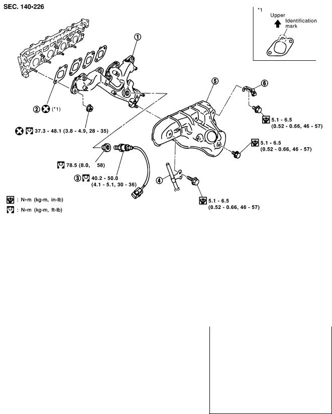
●Install gasket so that identification mark face as shown in component parts drawing.
EM-22
|
|
EXHAUST MANIFOLD |
|||
|
|
[KA24DE] |
|||
|
|
|
|
|
|
EXHAUST MANIFOLD |
PFP:14004 |
||||
Removal and Installation |
|
|
|
A |
|
EBS008RQ |
|||||
|
|
|
|
|
|
|
|
|
|
|
|
|
|
|
|
|
EM |
|
|
|
|
|
|
|
|
|
|
|
C |
|
|
|
|
|
D |
|
|
|
|
|
E |
|
|
|
|
|
F |
|
|
|
|
|
G |
|
|
|
|
|
H |
|
|
|
|
|
I |
|
|
KBIA0825E |
|
||
|
|
|
|
|
|
1 |
Exhaust manifold |
2 |
Gasket |
3 |
Heated oxygen sensor |
4 |
Oil level gauge guide |
5 |
Exhaust manifold cover |
6 |
Bracket |
REMOVAL
1. |
Remove under cover on rear side. |
||
2. |
Remove exhaust front tube. Refer to EX-2, "EXHAUST SYSTEM" . |
||
3. |
Open and fix engine compartment LH cover. |
||
4. |
Remove heated oxygen sensor with the following procedure. |
||
a. |
Remove engine compartment rear cover. Refer to EM-12, "ENGINE ROOM COVER" . |
||
b. |
Disconnect heated oxygen sensor harness connector from bracket on intake manifold No. 4 port, and |
||
|
remove all harness clamps. |
||
c. |
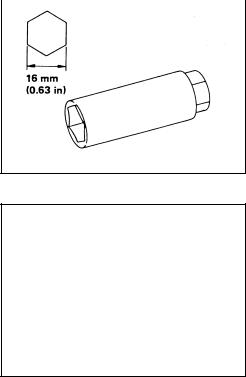
Using socket for heated oxygen sensor removal and installation |
|
|
|
|||
|
(special service tool), remove heated oxygen sensor. |
||
5. |
Remove exhaust manifold cover. |
||
KBIA0826E
J
K
L
M
EM-23

EXHAUST MANIFOLD
[KA24DE]
6.Loosen mounting nuts in reverse order shown in the figure, and remove exhaust manifold.
PBIC0430E
INSPECTION AFTER REMOVAL
●Using straightedge and feeler gauge, inspect surface distortion of intake manifold.
Limit |
: 0.3 mm (0.012 in) |
PBIC0431E
INSTALLATION
Install in the reverse order of removal, paying attention to the following.
●Tighten in numerical order as shown in the figure.
 : 37.3 - 48.1 N·m (3.8 - 4.9 kg-m, 28 - 35 ft-lb)
PBIC0430E
INSPECTION AFTER INSTALLATION
Start engine, and check for exhaust gas leakage and unusual noise by increasing engine speed.
EM-24

OIL PAN AND OIL STRAINER
|
|
|
|
[KA24DE] |
|
||
OIL PAN AND OIL STRAINER |
|
PFP:11110 |
|||||
Removal and Installation |
|
|
|
|
|
A |
|
|
|
EBS007KB |
|||||
|
|
|
|
|
|
|
|
|
|
|
|
|
|
|
|
|
|
|
|
|
|
|
EM |
|
|
|
|
|
|
|
|
|
|
|
|
|
|
|
C |
|
|
|
|
|
|
|
D |
|
|
|
|
|
|
|
E |
|
|
|
|
|
|
|
F |
|
|
|
|
PBIC0432E |
G |
||
|
|
|
|
|
|
||
1 |
Gasket |
2 |
Oil strainer |
3 Oil pan drain plug washer |
|||
4 |
Oil pan drain plug |
5 |
Oil pan |
|
|
|
H |
REMOVAL
WARNING:
To avoid the danger of being scalded, never drain the engine oil when the engine is hot.
1.Remove under covers on front-side, and rear-side.
2.Drain engine oil. Refer to LU-5, "ENGINE OIL" .
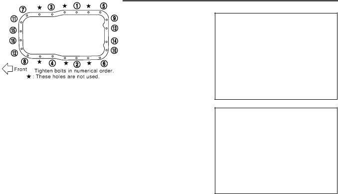
3.Loosen mounting bolts in reverse order shown in the figure, and remove them.
NOTE:
There are no screw holes in the area marked with  on cylinder block. (No mounting bolts.)
4.Using a seal cutter (special service tool), separate liquid gasket, and remove oil pan.
5.Remove oil strainer.
SEM980F
INSPECTION AFTER REMOVAL
Check oil strainer and clean it if any object attached.
INSTALLATION
Install in the reverse order of removal paying attention to the following.
I
J
K
L
M
EM-25
OIL PAN AND OIL STRAINER
[KA24DE]
Installing Oil Pan
1.Apply liquid gasket thoroughly as shown in illustration. ● Use Genuine Liquid Gasket or equivalent.
PBIC0433E
2.Tighten mounting bolts in numerical order as shown in the figure.
NOTE:
There are no screw holes in the area marked with  on cylinder block. (No mounting bolts.)
SEM985F
Installing Drain Plug Washer
Refer to illustration of component parts for installation direction.
INSPECTION AFTER INSTALLATION
Check for leakage of engine oil when engine is warmed.
EM-26
SPARK PLUG (CONVENTIONAL)
|
|
[KA24DE] |
|
|
SPARK PLUG (CONVENTIONAL) |
PFP:22401 |
|||
Removal and Installation |
|
|
A |
|
EBS008YM |
||||
REMOVAL |
|
|
|
|
1. |
Open and fix engine compartment LH cover. |
|
|
EM |
2. |
Disconnect high-tension cables from rocker cover. |
|
|
|
|
|
|
||
3. |
Remove spark plugs with a spark plug wrench (commercial ser- |
|
|
|
|
|
|
||
vice tool). |
C |
|
●Remove and install No. 4 cylinder by connecting extension bar of 75 mm and universal socket to spark plug wrench.
D
E
SMA581C
INSPECTION AFTER REMOVAL
Check spark plug gap. Adjust or replace if necessary.
Standard |
: 1.0 - 1.1 mm (0.039 - 0.043 in) |
|
Spark plug: |
|
|
Make |
|
NGK |
|
|
|
Standard type |
|
BKR5E-11 |
|
|
|
Cold type |
|
BKR6E-11 |
|
|
|
|
BKR7E-11 |
|
|
|
|
|
|
|
●Use a wire brush for cleaning, if necessary.
INSTALLATION
Install in the reverse order of removal, paying attention to the following.
Spark plug:
 : 20 - 29 N·m ( 2.0 - 3.0 Kg-m, 14 - 22 ft-lb)
F
G
H
I
SMA476
J
K
●Refer to EM-30, "ROCKER COVER" for installation of spark plug cap and high-tension cables.
L
M
EM-27
FUEL INJECTOR AND FUEL TUBE
|
[KA24DE] |
FUEL INJECTOR AND FUEL TUBE |
PFP:16600 |
Removal and Installation |
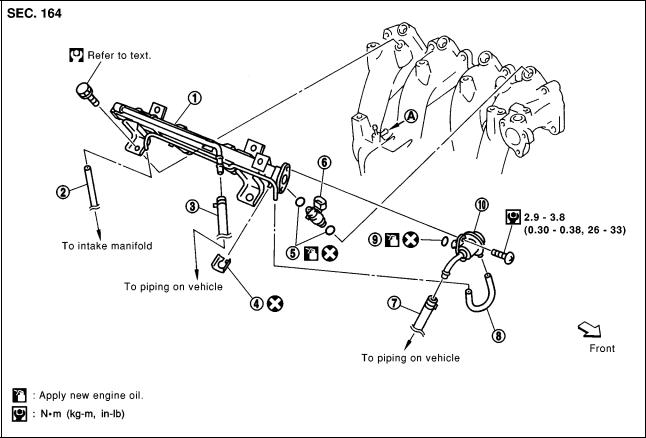
EBS007KE |
KBIA0827E
1 |
Fuel tube |
2 |
Vacuum hose |
3 |
Fuel feed hose |
4 |
Clip |
5 |
O-ring |
6 |
Fuel injector |
7 |
Fuel return hose |
8 |
Vacuum hose |
9 |
O-ring |
10 |
Fuel pressure regulator |
|
|
|
|
CAUTION:
●Apply new engine oil when installing the parts that specified to do so in the figure.
REMOVAL
1.Release fuel pressure. Refer to EC-27, "Fuel Pressure Release" .
2.Remove RH seat. Refer to SE-4, "FRONT SEAT" .
3.Remove engine compartment RH cover. Refer to EM-12, "ENGINE ROOM COVER" .
4.Disconnect PCV hose between rocker cover and air duct.
5.Remove air duct on throttle body. Refer to EM-16, "AIR CLEANER AND AIR DUCT" .
6.Disconnect fuel injector harness connector.
7.Move aside main harness above intake manifold.
8.Disconnect vacuum hose from fuel tube.
9.Disconnect fuel feed hose and fuel return hose.
CAUTION:
Plug hoses to prevent fuel from draining.
10.Remove fuel tube and injector assembly.
CAUTION:
Do not incline it, or remaining fuel in pipes may drain from pipes.
EM-28

FUEL INJECTOR AND FUEL TUBE
[KA24DE]
11.Expand and remove clips securing fuel injectors.
12.Extract fuel injectors straight from fuel tubes.
●Be careful not to damage injector nozzles during removal.
●Do not bump or drop fuel injectors.
●Do not disassemble.
PBIC0227E
INSTALLATION
1. |
Carefully install O-rings, including the one used with the pressure regulator. |
● |
Lubricate O-rings by smearing new engine oil. |
● |
Be careful not to damage O-rings and surfaces for O-ring sealing with service tools, finger nails or |
|
clips. Do not expand or twist O-rings. |
● |
Discard old clips; replace with new ones. |
2.Position clips in grooves on fuel injectors.
●Make sure that protrusions of fuel injectors are aligned with cutouts of clips after installation.
3.Align protrusions of fuel tubes with those of fuel injectors.
4.Do not incline it, or remaining fuel in pipes may drain from pipes.
●Insert hose until its end touches bulge on fuel tube. Install clamp, avoiding bulge, and securely tighten it.
5.Tighten fuel tube assembly mounting bolts alternatively in two steps.
PBIC0227E
 1st step : 7.8 - 10.8 N·m (0.8 - 1.1 kg-m, 69 - 95 ft-lb)
 2nd step :15.7 - 18.6 N·m (1.6 - 1.8 kg-m, 12 - 13 ft-lb)
6.Connect fuel feed nose and fuel return hose.
●Insert hose until its end touches bulge on fuel tube. Install clamp, avoiding bulge, and securely tighten it.
7.Install all removed parts in the reverse order of removal.
A
EM
C
D
E
F
G
H
I
J
K
INSPECTION AFTER INSTALLATION
Check on Fuel Leakage
1.Start the engine, and run it for a few minutes with engine at idle.
2.Stop the engine, and check for fuel leakage both visually and by odor of gasoline.
NOTE:
Use mirrors for checking on invisible points.
CAUTION:
Do not touch the engine immediately after stopped, as engine becomes extremely hot.
L
M
EM-29

|
ROCKER COVER |
|
[KA24DE] |
|
|
ROCKER COVER |
PFP:13264 |
Removal and Installation |
EBS007KF |
KBIA0828E
1 |
PCV hose |
2 |
Oil filler cap |
3 Rocker cover |
4 |
Gasket |
5 |
Gasket |
|
REMOVAL
1.Open and fix engine compartment LH cover.
2.Remove engine compartment rear cover. Refer to EM-12, "ENGINE ROOM COVER" .
3.Disconnect PCV hose.
4.Disconnect spark plug cap and high-tension cables, and set them aside.
5.Loosen mounting bolts in reverse order shown in the figure, and remove rocker cover.
PBIC0434E
INSTALLATION
Install in the reverse order of removal, paying attention to the following.
EM-30
 Loading...