


1! .6L 4-CYL - VIN [E]
1993! Nissan Sentra
1993 NISSAN ENGINES
1.6L 4-Cylinder NX, Sentra
* PLEASE READ THIS FIRST *
NOTE: For engine repair procedures not covered in this article, see ENGINE OVERHAUL PROCEDURES - GENERAL INFORMATION article in the GENERAL INFORMATION section.
ENGINE IDENTIFICATION
Engine can be identified by fourth character of Vehicle Identification Number (VIN). See ENGINE IDENTIFICATION CODE table. VIN is located on top left end of instrument panel, near windshield. Engine serial number is stamped on rear of cylinder block, left of flywheel.
ENGINE IDENTIFICATION CODES TABLE
Application |
Engine Code |
VIN Code |
NX & Sentra |
|
|
1.6L 4-Cylinder |
.......... GA16DE ...................... |
E |
|
|
|
ADJUSTMENTS
VALVE CLEARANCE ADJUSTMENT
NOTE: Check valve clearance when engine is hot.
Checking Valve Clearance
1)Disconnect negative battery cable. Remove spark plugs. Rotate crankshaft until cylinder No. 1 is at TDC of compression stroke. Ensure timing mark on crankshaft pulley aligns with "0" mark on timing belt cover.
2)Ensure valve lifters on cylinder No. 1 are loose and valve lifters on cylinder No. 4 are tight. Using feeler gauge, measure and record clearance between valve lifter and camshaft at valves specified in VALVE CLEARANCE CHECKING SEQUENCE table.
VALVE CLEARANCE CHECKING SEQUENCE TABLE
Cylinder No. |
Check Intake |
Check Exhaust |
||
At TDC |
Valves |
No. |
Valves |
No. |
1 ...................... |
1 & |
2 .................... |
1 |
& 3 |
4...................... 3 & 4 .................... 2 & 4
3)To check remaining valves, rotate crankshaft 360 degrees (cylinder No. 4 at TDC of compression stroke). Measure and record valve clearance at remaining valves. If clearance is not as follows, adjust valves.
*Exhaust - .012-.023" (.30-.58 mm)
*Intake - .008-.019" (.21-.49 mm)
NOTE: Adjust valve clearance when engine is cold.
Adjusting Valve Clearance
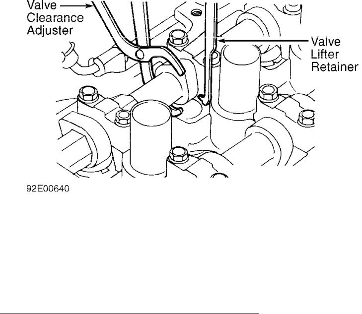
1) Rotate camshaft until lobe is facing upward, away from valve lifter. Rotate valve lifter so notch on valve lifter is facing center of cylinder head. Rotate Valve Clearance Adjuster (J38972-1) to push valve lifter downward. See Fig. 1.
Fig. 1: Adjusting Valve Clearance
Courtesy of Nissan Motor Co., U.S.A.
2)Place Valve Lifter Retainer (J38972-2) between camshaft and valve lifter. Remove valve clearance adjuster. Using a magnet and small screwdriver, remove shim. Using a micrometer, measure thickness of shim removed.
3)If valve clearance is not as specified, install appropriate size shim. Shims are available in 50 sizes, ranging in thickness from .0787" (2.00 mm) to .1173" (2.98 mm) in increments of . 0008" (.020 mm). Thickness is stamped in millimeters on bottom face of shim.
4)Ensure clearance is as specified in VALVE CLEARANCE SPECIFICATIONS (ADJUSTING) table (use cold specification). Install cylinder head cover. Tighten bolts to specification. See TORQUE SPECIFICATIONS. Recheck clearance when engine is warm.
VALVE CLEARANCE SPECIFICATIONS (ADJUSTING) TABLE
|
Cold |
|
(1) Hot |
|
Valve |
In. (mm) |
|
In. (mm) |
|
Exhaust ...... |
.013-.016 |
(.32-.40) ...... |
.015-.018 |
(.37-.45) |
Intake ....... |
.010-.013 |
(.25-.32) ...... |
.013-.016 |
(.32-.40) |
(1)- Although hot specifications are provided, adjust valve clearance to cold specification.
REMOVAL & INSTALLATION
NOTE: For reassembly reference, label all electrical connectors, vacuum hoses and fuel lines before removal. Also place mating marks on engine hood and other major assemblies before removal.
FUEL PRESSURE RELEASE
Remove fuel pump fuse. Start engine. After engine stalls, crank engine 2-3 times to ensure fuel pressure is released. Turn ignition off. Install fuel pump fuse.
ENGINE
NOTE: Remove engine and transaxle as an assembly through bottom of engine compartment.
Removal
1)Release fuel pressure. See FUEL PRESSURE RELEASE. Drain cooling system. Remove hood and battery. Remove reservoir tank and bracket. Remove accessory drive belts. Remove alternator. Remove A/C compressor and power steering pump, leaving hoses attached.
2)Remove front tires and engine undercovers. Leaving brake hoses attached, remove brake caliper. Disconnect lower ball joint and tie rod from steering knuckle. Pry axle shaft from transaxle. Repeat procedure for other side.
3)On M/T models, disconnect control rod and support rod from transaxle. Remove buffer rod from crossmember. On A/T models, disconnect control cable from transaxle. On all models, remove crossmember, front exhaust pipe, stabilizer, radiator fan and radiator.
4)Mark and disconnect electrical connectors, wiring harnesses and vacuum hoses as necessary. Raise and support vehicle. Support engine from bottom. Remove front engine mount. Raise engine slightly, and remove remaining engine mounts. Remove engine and transaxle as an assembly through bottom of engine compartment.
Installation
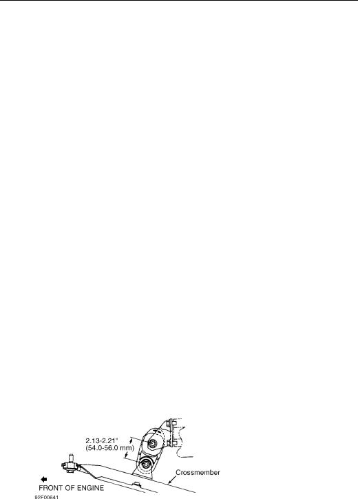
To install, reverse removal procedure. When installing buffer rod (M/T models), adjust height between bolts. See Fig. 2. Ensure all engine mounts are installed in original positions.
Fig. 2: Adjusting Buffer Rod Height (M/T Models)
Courtesy of Nissan Motor Co., U.S.A.
INTAKE & EXHAUST MANIFOLDS
Removal & Installation
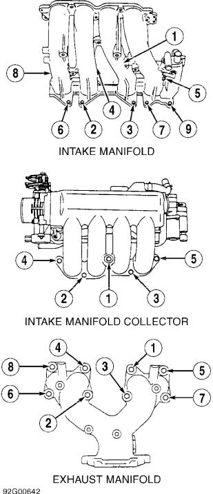
Removal and installation procedure is not available from manufacturer. For tightening sequence, see Fig. 3
Fig. 3: Exhaust & Intake Manifold Tightening Sequence Courtesy of Nissan Motor Co., U.S.A.
CYLINDER HEAD
CAUTION: If camshaft or crankshaft is rotated with timing chain disconnected, piston will contact valves, resulting in bent valves.
Removal
1)Release fuel pressure. See FUEL PRESSURE RELEASE. Drain coolant from radiator and cylinder block (drain plug is on left side of block, between flywheel and exhaust manifold). Remove accessory drive belts and power steering pump bracket. Remove intake air duct. Remove right front wheel and splash shield.
2)Remove engine undercovers. Remove front exhaust pipe. Remove front engine mount. Remove cylinder head cover, distributor cap and spark plugs. Set piston No. 1 at TDC of compression stroke.
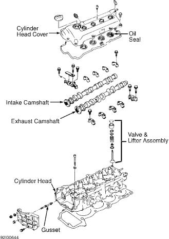
3)For reference, mark rotor in relation to distributor housing and distributor housing in relation to cylinder head. Remove distributor. Remove camshaft sprocket cover and gusset. See Fig. 4. Remove water pump pulley and thermostat housing.
4)Remove chain tensioner and guide. See Fig. 6. Loosen idler sprocket bolt. Remove camshaft sprockets. Mark and remove camshaft journal caps. Remove camshafts. Remove idler sprocket bolt. Remove cylinder head bolts in 2 steps, in sequence. See Fig. 5. Remove cylinder head with manifolds. Remove manifolds from cylinder head.
Fig. 4: Exploded View Of Cylinder Head Courtesy of Nissan Motor Co., U.S.A.

Fig. 5: Cylinder Head Bolt Removal & Installation Sequence Courtesy of Nissan Motor Co., U.S.A.
Inspection
Clean cylinder head gasket mating surfaces. Check cylinder
head for warpage. If warpage exceeds specification, resurface or replace cylinder head as necessary. See CYLINDER HEAD table under ENGINE SPECIFICATIONS. DO NOT remove more than .008" (.20 mm) material from cylinder head and/or cylinder block surfaces (combined total).
Installation
Install new cylinder head gasket and cylinder head. Tighten cylinder head bolts in sequence. See Fig. 5. Tighten bolts to specification. See TORQUE SPECIFICATIONS. For alignment of timing chain and gear marks, see TIMING CHAIN under REMOVAL & INSTALLATION. To complete installation, reverse removal procedure.
FRONT COVER OIL SEAL
NOTE: Manufacturer lists front cover oil seal removal and installation with front cover removed from engine.
Removal & Installation
1)Release fuel pressure. See FUEL PRESSURE RELEASE. Drain coolant from radiator and cylinder block (drain plug is on left side of block, between flywheel and exhaust manifold). Remove accessory drive belts and power steering pump bracket. Remove intake air duct. Remove right front wheel and splash shield.
2)Remove engine undercovers. Remove front exhaust pipe. Remove front engine mount. Remove distributor cap and spark plugs. Set piston No. 1 at TDC of compression stroke.
3)Remove camshaft sprocket cover and gusset. See Fig. 4. Remove water pump pulley and thermostat housing. Remove chain tensioner and guide. See Fig. 6. Loosen idler sprocket bolt. Remove camshaft sprockets. Remove idler sprocket bolt.
4)Remove front crossmember and oil pan. Remove crankshaft pulley. Support engine using a jack. Remove front engine mount. Remove front cover.
5)Pry out oil seal from front cover. Apply oil and install seal into front cover. To complete installation, reverse removal procedure. Tighten all nuts and bolts to specification. See TORQUE SPECIFICATIONS.
TIMING CHAIN
CAUTION: If camshaft or crankshaft is rotated with timing chain disconnected, piston will contact valves, resulting in bent valves.
Removal
1)Release fuel pressure. See FUEL PRESSURE RELEASE. Drain coolant from radiator and cylinder block (drain plug is on left side of block, between flywheel and exhaust manifold). Remove accessory drive belts and power steering pump bracket. Remove intake air duct. Remove right front wheel and splash shield.
2)Remove engine undercovers. Remove front exhaust pipe. Remove front engine mounting bracket. Remove cylinder head cover, distributor cap and spark plugs. Set piston No. 1 at TDC of compression stroke.
3)Remove camshaft sprocket cover and gusset. See Fig. 4. Remove water pump pulley and thermostat housing. Remove chain tensioner and guide. See Fig. 6. Loosen idler sprocket bolt. Remove camshaft sprockets. Remove idler sprocket bolt. Remove idler sprocket from rear. Remove outer (upper) timing chain.
4)Remove crossmember and rear engine mount. Remove oil pan and strainer. Remove crankshaft pulley. Support engine using a jack. Remove front engine mount. Remove front cover bolts (one of these bolts retains water pump and front cover). Remove front cover. Remove
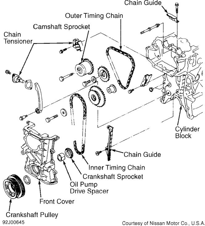
idler sprocket, inner (lower) timing chain and oil pump drive spacer. Remove chain guide and crankshaft sprocket.
Fig. 6: Exploded View Of Timing Chain Components
Courtesy of Nissan Motor Co., U.S.A.
Installation
1) Ensure cylinder No. 1 is at TDC of compression stroke.
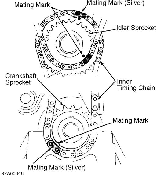
Install chain guide, crankshaft sprocket and inner timing chain. Align inner timing chain mating mark (Silver link) with marks on crankshaft sprocket. See Fig. 7.
2)Apply liquid gasket to front cover. Ensure 2 "O" rings are in place on front cover. Install oil pump drive spacer, front cover and oil pan. Install front engine mount, crossmember and crankshaft pulley. Install idler sprocket with outer timing chain. Align inner timing chain mating mark (Silver link) with marks on idler sprocket. See Fig. 7.
3)Install idler sprocket shaft from rear. Install camshaft sprocket with outer timing chain. Align outer timing chain mating marks with marks on camshaft sprocket. See Fig. 8. To complete installation, reverse removal procedure. Tighten all nuts and bolts to specification. See TORQUE SPECIFICATIONS.
Fig. 7: Aligning Inner Timing Chain Marks Courtesy of Nissan Motor Co., U.S.A.
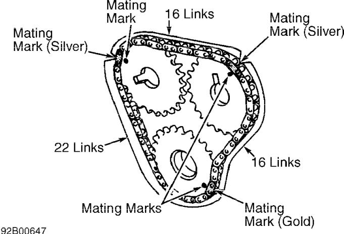
Fig. 8: Aligning Outer Timing Chain Marks
Courtesy of Nissan Motor Co., U.S.A.
CAMSHAFT
Removal
Manufacturer’s procedure requires cylinder head removal. See CYLINDER HEAD. Keep camshaft journal caps in order of removal for reassembly reference.
Inspection
Check camshaft for wear. If camshaft dimensions are not within specification, replace camshaft and/or cylinder head as necessary. See CAMSHAFT table under ENGINE SPECIFICATIONS.
Installation
1)Lubricate camshafts before installation. Install camshafts and journal caps, ensuring camshafts are correctly aligned and journal caps are tightened in correct sequence. See Fig. 9.
2)To complete installation, reverse removal procedure. Tighten all nuts and bolts to specification. See TORQUE SPECIFICATIONS.
Fig. 9: Installing Camshafts & Journal Caps Courtesy of Nissan Motor Co., U.S.A.
REAR CRANKSHAFT OIL SEAL
Removal & Installation
Remove transaxle and flywheel/flexplate. Remove and clean rear oil seal retainer. Remove seal from rear oil seal retainer. Apply engine oil to new oil seal. Install oil seal. Apply liquid gasket to rear oil seal retainer. Reverse removal procedure to complete installation. Tighten all nuts and bolts to specification. See TORQUE SPECIFICATIONS.
WATER PUMP
NOTE: For further information on cooling systems, See SPECIFICATIONS & ELECTRIC COOLING FANS article in the ENGINE COOLING Section.
Removal
Drain coolant from radiator and cylinder block (drain plug is on left side of block, between flywheel and exhaust manifold). Remove accessory drive belts. Remove water pump pulley and water pump. DO NOT allow coolant to contact timing chain.
Inspection
Check pump body and vane for corrosion. Ensure vane turns easily without roughness. Remove all gasket material from pump housing mating surfaces.
Installation
Apply a small bead of liquid gasket to pump housing mating surface. Install pump. To install remaining components, reverse removal procedure. Tighten all nuts and bolts to specification. See TORQUE SPECIFICATIONS.
OIL PAN
Removal
Remove engine undercover. Drain oil. Remove crossmember. Remove front exhaust pipe. Remove oil pan bolts. Remove oil pan using Oil Pan Separator (KV10111100) to separate oil pan from cylinder block (if necessary).
Installation
Clean all gasket sealing surfaces. Apply a continuous .14-. 17" (3.5-4.5 mm) wide bead of liquid gasket to oil pan, running bead inside groove and inward of bolt holes. To complete installation, reverse removal procedure. Tighten all nuts and bolts to specification. See TORQUE SPECIFICATIONS. DO NOT add oil until 30 minutes after installing oil pan.
OVERHAUL
CYLINDER HEAD
CAUTION: DO NOT remove more than .008" (.20 mm) of material from cylinder head and/or cylinder block surfaces combined.
Cylinder Head
Check for warpage at gasket surface area. Replace or resurface cylinder head if warpage exceeds specification. See CYLINDER HEAD table under ENGINE SPECIFICATIONS. If cylinder head height is not within specification or camshaft resists being rotated by hand after machining, replace cylinder head.
CAUTION: Install valve springs with tightest coil area or paint mark toward cylinder head.
Valve Springs
Ensure valve spring free length, out-of-square and pressure are within specification. See VALVES & VALVE SPRINGS table under ENGINE SPECIFICATIONS.
Valve Stem Oil Seals
Lubricate valve stem oil seal with engine oil. Install oil seal using Oil Seal Installer (J-38958). Ensure oil seal is fully seated on valve guide.
Valve Guides
1)Heat cylinder head to 230-248  F (110-120
  C). Using a hammer and drift or a shop press, drive guide out through top of cylinder head. Allow cylinder head to cool to room temperature.
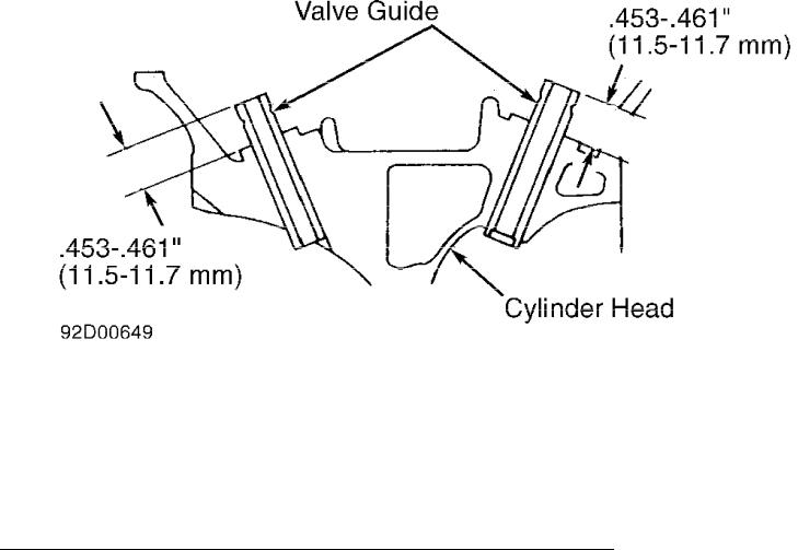
2)Ream valve guide bore to .3813-.3817" (9.685-9.696 mm). Heat cylinder head to 230-248  F (110-120
  C). Press new guide into guide bore until guide protrudes .453-.461" (11.50-11.70 mm) out of top of guide bore. See Fig. 10.
3)Allow cylinder head to cool to room temperature. Ream valve guide inside diameter to .2165-.2171" (5.500-5.515 mm).
Fig. 10: Measuring Installed Valve Guide Protrusion
Courtesy of Nissan Motor Co., U.S.A.
Valve Seat
1)Before servicing or replacing valve seat, repair valve guides. Bore valve seat until it collapses. Remove seat. Ream valve seat bore for .02" (.5 mm) oversize. See VALVE SEAT REPLACEMENT BORE table.
2)Heat cylinder head to 230-248  F (110-120
  C). Press valve seat into bore until it is fully seated. Grind or cut valve seat. See CYLINDER HEAD table under ENGINE SPECIFICATIONS. After machining, lap valve seat with lapping compound.
VALVE SEAT REPLACEMENT BORE TABLE
Application |
In. (mm) |
Intake ............................... |
1.2402-1.2408 (31.500-31.510) |
Exhaust .............................. |
1.0039-1.0046 (25.500-25.510) |
|
|
Valves
Check valve dimensions. See VALVES & VALVE SPRINGS table under ENGINE SPECIFICATIONS. Replace valve if dimensions are not within specification.
CYLINDER BLOCK ASSEMBLY
Piston & Rod Assembly
1) To disassemble piston and connecting rod, remove snap ring from piston. Heat piston in oil to 140-158  F(60-70
  C). Press piston pin out of connecting rod.
2)Ensure piston pin fit and rod fit are within specification. See PISTONS, PINS & RINGS table under ENGINE SPECIFICATIONS. Replace piston, connecting rod and/or pin if it is not within specification. Ensure connecting rod bend and twist do not exceed specification. See CONNECTING RODS table under ENGINE SPECIFICATIONS.
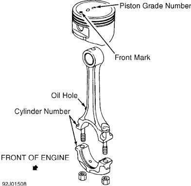
3)To reassemble, install NEW snap ring into piston pin bore.
Heat piston in oil to 140-158  F (60-70
  C). Assemble piston, piston pin, connecting rod and remaining NEW snap ring, with oil hole in rod facing right side of engine. See Fig. 11. Ensure pin and rod are centered in piston.
4) After reassembly, ensure connecting rod swings smoothly. Install piston with front mark on piston toward front of engine. Ensure cylinder identification number on rod and cap are on same side.
Fig. 11: Exploded View Of Piston & Rod Assembly
Courtesy of Nissan Motor Co., U.S.A.
Piston Pin Bushing Replacement
Use proper driver to remove piston pin bushing. When
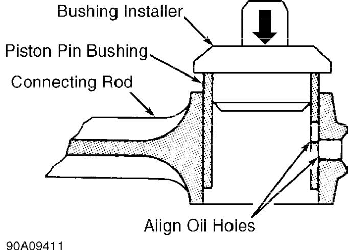
installing new bushing, ensure oil holes are aligned. See Fig. 12. After installing bushing, ream bushing for proper rod fit (piston pin- to-bushing clearance). See PISTONS, PINS & RINGS table under ENGINE SPECIFICATIONS.
Fig. 12: Installing Piston Pin Bushing Into Connecting Rod Courtesy of Nissan Motor Co., U.S.A.
Fitting Pistons
1)Standard diameter of cylinder bores may differ slightly from cylinder to cylinder. To compensate for these differences and achieve closer tolerances, standard size pistons are available in slightly different diameters.
2)A grade number, stamped on top of piston, represents piston diameter. See Fig. 11. Grade number stamped on bottom of cylinder block represents cylinder bore diameter. See Fig. 20. Piston grade number must match cylinder bore grade number.
3)Measure piston diameter at .374" (9.50 mm) from bottom of piston, at 90-degree angle to piston pin. If piston clearance, cylinder bore diameter, out-of-round or taper exceed specification, rebore all cylinders or replace cylinder block. See CYLINDER BLOCK table under ENGINE SPECIFICATIONS. Oversize pistons are available in . 020" (.50 mm) and .039" (1.00 mm) oversize. See CYLINDER BLOCK for reboring information.
Piston Rings
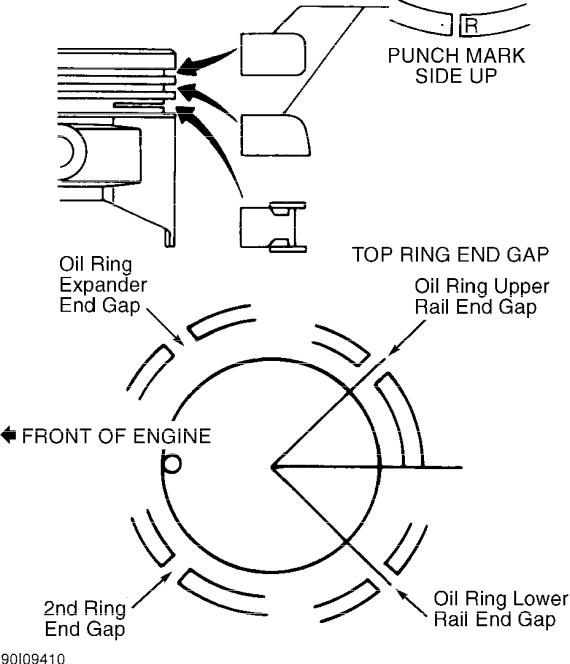
Measure ring side clearance. If ring side clearance exceeds specification, replace rings and/or piston. See PISTONS, PINS & RINGS table under ENGINE SPECIFICATIONS. Measure ring end gap. If ring end gap exceeds specification, replace piston ring. If ring end gap still exceeds specification, rebore cylinder and install oversize pistons and rings. If ring is punch-marked, install ring on piston with punch mark facing up. See Fig. 13.
Fig. 13: Positioning Piston Rings
Courtesy of Nissan Motor Co., U.S.A.
Rod Bearings
1) Standard diameter of rod bearing journals may differ
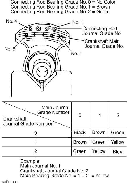
slightly from cylinder to cylinder. To compensate for these differences and achieve closer tolerances, standard size rod bearings are available in slightly different diameters.
2) A grade number, stamped on crankshaft throw, represents diameter of specific rod bearing journal. See Fig. 14. A color code on side of rod bearing represents grade number of rod bearing (grade number of rod bearing represents thickness of rod bearing). Ensure grade number of rod bearing journal matches grade number (color) of rod bearing. See Fig. 14 to determine color code of rod bearings to be installed.
Fig. 14: Identifying Grade Numbers Of Crankshaft Connecting Rod & Main Bearing Journals
Courtesy of Nissan Motor Co., U.S.A.
3) Measure rod bearing clearance. If rod bearing clearance
exceeds specification, replace rod bearings or machine rod bearing journal and install undersize bearings. See CRANKSHAFT, MAIN & CONNECTING ROD BEARINGS table under ENGINE SPECIFICATIONS. Undersize bearings are available in .0031" (.080 mm), .0047" (.120 mm) and . 0098" (.250 mm) undersize.
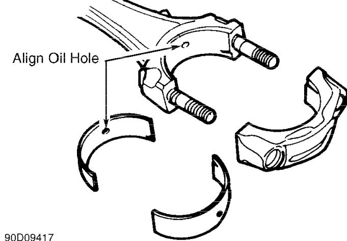
4)When installing rod bearings, ensure oil hole in connecting rod aligns with oil hole in rod bearing. See Fig. 15. When installing rod bearing cap, ensure cylinder identification number on rod and cap are on same side. See Fig. 11.
5)Tighten connecting rod bearing cap nuts evenly to specification. See TORQUE SPECIFICATIONS. Measure connecting rod side play. If side play is not within specification, replace connecting rod and/or crankshaft.
Fig. 15: Aligning Connecting Rod Bearing Oil Holes
Courtesy of Nissan Motor Co., U.S.A.
Crankshaft & Main Bearings
1)Loosen main bearing caps evenly in sequence in 2-3 steps. See Fig. 16. Main bearing caps are marked for reassembly reference. See Fig. 17. Upper and lower main bearings are not interchangeable. Main bearing upper half can be identified by oil groove. See Fig. 19.
2)Standard diameters of main bearing journals and main bearing journal block bores may differ slightly from cylinder to cylinder. To compensate for these differences and achieve closer tolerances, standard size main bearings are available in slightly different diameters.
3)A grade number, stamped on crankshaft throw, represents diameter of specific main bearing journal. See Fig. 14. Grade number stamped on bottom of cylinder block represents diameter of specific main bearing journal block bore. See Fig. 20. A color code on side of main bearing represents main bearing size. See Fig. 19. Use table in Fig. 14 or 20 to determine color code of main bearings to be installed.
4)Determine main bearing oil clearance. If oil clearance is not within specification, replace main bearings or machine crankshaft and install undersize bearings. See CRANKSHAFT, MAIN & CONNECTING ROD BEARINGS table under ENGINE SPECIFICATIONS.
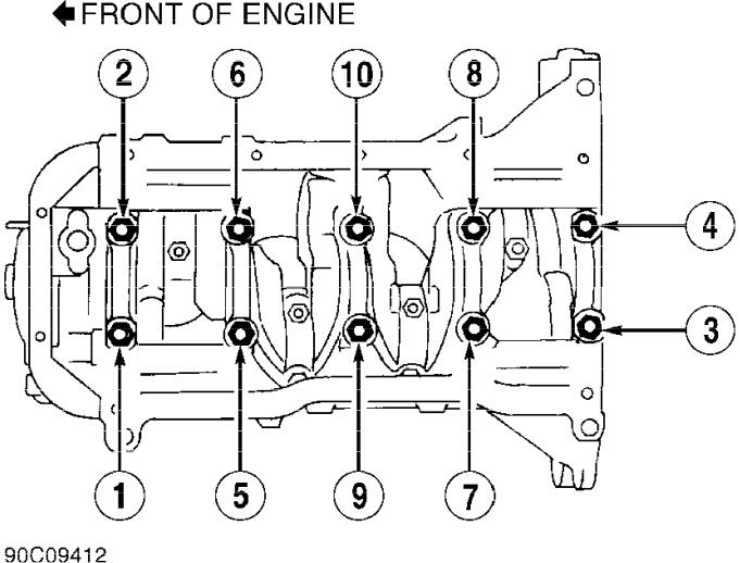
5)Undersize bearings are available in .0098" (.250 mm) and . 0197 (.500 mm) undersize. Tighten main bearing cap bolts in sequence. See Fig. 18. Tighten evenly in 2-3 steps to specification. See TORQUE SPECIFICATIONS.
Fig. 16: Main Bearing Cap Loosening Sequence Courtesy of Nissan Motor Co., U.S.A.
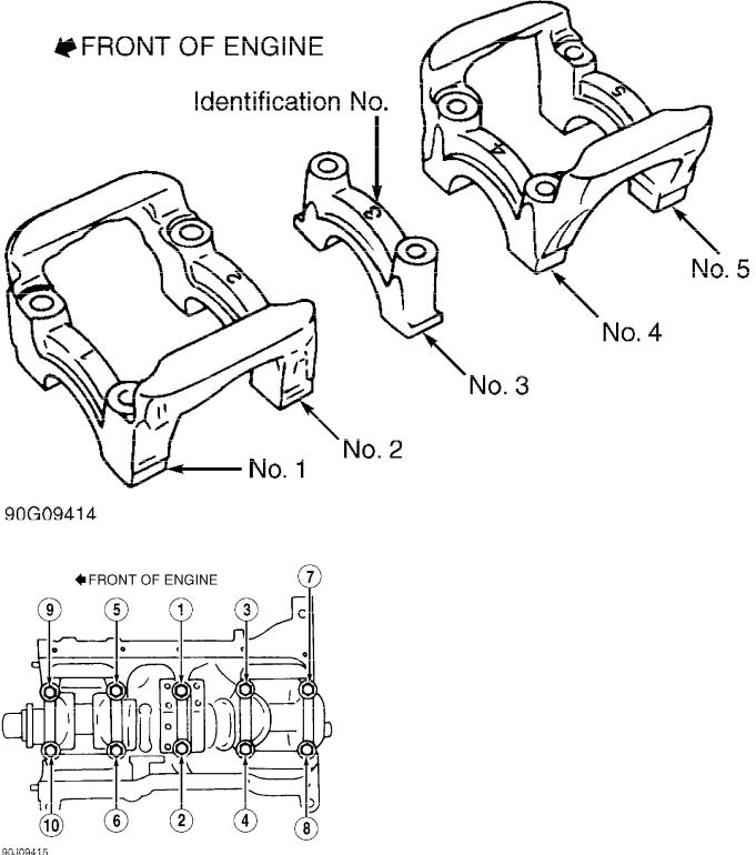
Fig. 17: Identifying Main Bearing Caps
Courtesy of Nissan Motor Co., U.S.A.
Fig. 18: Main Bearing Cap Tightening Sequence
Courtesy of Nissan Motor Co., U.S.A.
Thrust Bearing
Center (No. 3) main bearing is thrust bearing. See Fig. 19.
If crankshaft end play is not within specification, replace thrust bearing. See CRANKSHAFT, MAIN & CONNECTING ROD BEARINGS table under ENGINE SPECIFICATIONS.
Fig. 19: Positioning Main Bearing Cap & Identifying Grade Courtesy of Nissan Motor Co., U.S.A.
Cylinder Block
1)If maximum deck warpage exceeds specification, machine or replace cylinder block. See CYLINDER BLOCK table under ENGINE SPECIFICATIONS. Replace cylinder block if machining deck surface reduces deck height to less than minimum specification.
2)If cylinder bore diameter, out-of-round or taper exceeds specification, rebore all cylinders or replace cylinder block. See CYLINDER BLOCK table under ENGINE SPECIFICATIONS. If reboring cylinders, ensure all cylinders are rebored to same size.
3)Before reboring, install main bearing caps and tighten bolts to specification to prevent cylinder distortion. See TORQUE SPECIFICATIONS. Cylinder can be rebored to .020" (.50 mm) or .039" (1. 00 mm) oversize. Hone cylinder bore for proper piston fit. See
Fig. 20.
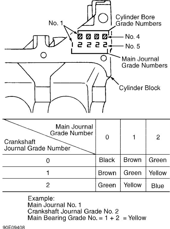
Fig. 20: Identifying Grade Numbers Of Cylinder Bore & Main Bearing Journal Block Bore
Courtesy of Nissan Motor Co., U.S.A.

ENGINE OILING
ENGINE LUBRICATION SYSTEM
Crankcase Capacity
Oil capacity is 3.0 qts. (2.8L) without filter and 3.4 qts. (3.2L) with filter change.
Oil Pressure
Oil pressure should be 7-27 psi (0.5-1.9 kg/cm  ) at idle and 50-64 psi (3.5-4.5 kg/cm
  ) at 3000 RPM.
OIL PUMP
Removal & Installation
Oil pump is part of front cover. Oil pump gears are accessible from inside of front cover. For removal and installation of front cover, see FRONT COVER OIL SEAL under REMOVAL & INSTALLATION.
Inspection
Check oil pump clearances. See Figs. 21 and 22. If inner gear-to-crescent clearance is not within specification, replace gear set. See OIL PUMP SPECIFICATIONS table. If any other clearances are not within specification, replace front cover.
OIL PUMP SPECIFICATIONS TABLE
Application |
|
In. (mm) |
Body-To-Outer Gear ............... |
.0043-.0079 (.110-.200) |
|
Inner Gear-To-Brazed Portion |
|
|
Of Housing ...................... |
.0018-.0036 (.045-.091) |
|
Inner Gear-To-Crescent ........... |
.0085-.0129 |
(.217-.327) |
Outer Gear-To-Crescent ........... |
.0083-.0126 |
(.210-.320) |
Side Clearance (1) |
|
|
Inner Gear ...................... |
.0020-.0035 |
(.050-.089) |
Outer Gear ...................... |
.0020-.0043 |
(.050-.110) |
(1)- To measure, lay straightedge across gears and front cover (gasket removed). Insert feeler gauge between gear and straightedge.
Fig. 21: Checking Oil Pump Clearances Courtesy of Nissan Motor Co., U.S.A.
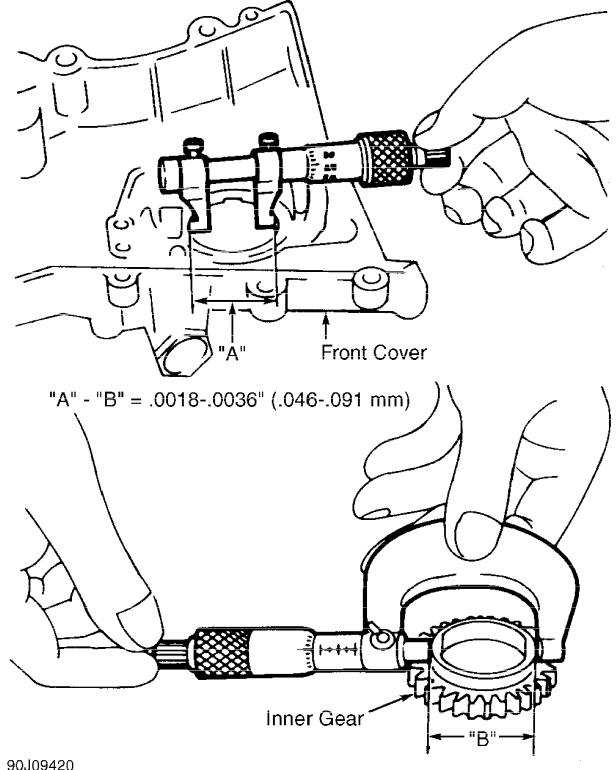
Fig. 22: Checking Clearance Between Inner Gear & Brazed Portion Of Oil Pump Housing
Courtesy of Nissan Motor Co., U.S.A.

TORQUE SPECIFICATIONS
TORQUE SPECIFICATIONS TABLE
Application |
Ft. Lbs. (N.m) |
Camshaft Sprocket Bolt .................... |
72-94 (98-127) |
Connecting Rod Nuts ........................ |
17-21 (23-28) |
Crankshaft Pulley Bolt .................. |
98-112 (133-152) |
Cylinder Head Bolt (1) |
|
1-10 (Large Bolt) |
|
1st Step ........................................ |
22 (30) |
2nd Step ........................................ |
43 (58) |
3rd Step ........................ |
Loosen Bolts Completely |
4th Step ........................................ |
22 (30) |
5th Step ........................................ |
43 (58) |
11-15 (Small Bolt) |
|
6th Step ............................................ |
(2) |
Exhaust Manifold Nut (3) ................... |
12-15 (16-20) |
Exhaust Pipe-To-Manifold Nut ............... |
21-25 (28-34) |
Flexplate Bolt ............................ |
69-76 (94-103) |
Flywheel Bolt .............................. |
61-69 (83-94) |
Idler Sprocket Bolt ........................ |
32-43 (43-58) |
Intake Manifold Nut (3) .................... |
12-15 (16-20) |
Intake Manifold Collector-To-Intake |
|
Manifold Bolt (3) ......................... |
12-15 (16-20) |
Main Bearing Cap Bolt ...................... |
34-38 (46-52) |
Oil Pressure Regulator Valve Plug .......... |
29-43 (39-59) |
Oil Pump Pick-Up Tube Bolts ................ |
12-14 (16-19) |
Spark Plugs ................................ |
14-22 (19-30) |
|
INCH Lbs. (N.m) |
Camshaft Journal Cap Bolt .............. |
79-103 (9.0-11.5) |
Cylinder Head Cover Bolt ................. |
17-35 (2.0-4.0) |
Front Cover Bolt ......................... |
55-73 (6.2-8.3) |
Inner Timing Chain Tensioner Bolt ........ |
54-73 (6.1-8.3) |
Oil Pan Bolt ............................. |
55-73 (6.2-8.3) |
Oil Pump Cover Bolt ...................... |
54-73 (6.1-8.3) |
Oil Pump Cover Screw ..................... |
30-42 (3.7-5.0) |
Outer Timing Chain Tensioner Bolt ...... |
51-108 (5.8-12.2) |
Water Pump Bolt .......................... |
54-73 (6.1-8.3) |
Water Pump Pulley Bolt ................... |
54-73 (6.1-8.3) |
(1)- Tighten in sequence. See Fig. 5.
(2)- Tighten in sequence to 55-73 INCH lbs. (6.2-8.3 N.m).
(3)- Tighten in sequence. See Fig. 3.
ENGINE SPECIFICATIONS
GENERAL ENGINE SPECIFICATION
GENERAL SPECIFICATIONS TABLE
Application |
Specification |
||
Displacement ......................... |
97.5 Cu. In. (1.6L) |
||
Bore ....................................... |
2.99" |
(76 |
mm) |
Stroke ..................................... |
3.47" |
(88 |
mm) |
Compression Ratio .................................. |
|
9.5:1 |
|

Compression Pressure ......................... |
164-192 psi |
Fuel System .......................................... |
PFI |
Horsepower @ RPM ..................................... |
N/A |
Torque Ft. Lbs. @ RPM ................................ |
N/A |
|
|
CRANKSHAFT, MAIN & CONNECTING
ROD BEARINGS SPECIFICATIONS
CRANKSHAFT, MAIN & CONNECTING ROD BEARINGS TABLE
Application |
In. (mm) |
|
Crankshaft |
|
|
End Play |
|
|
Standard |
........................ |
.0024-.0071 (.061-.180) |
Service |
Limit ................................ |
.012 (.30) |
Main Bearings |
|
|
Journal |
Diameter |
|
Grade 0 |
(1) ............... |
1.9668-1.9671 (49.957-49.964) |
Grade 1 |
(1) ............... |
1.9665-1.9668 (49.948-49.957) |
Grade 2 |
(1) ............... |
1.9661-1.9665 (49.940-49.948) |
Journal |
Out-Of-Round ....................... |
.0002 (.005) |
Journal |
Taper .............................. |
.0001 (.002) |
Oil Clearance ................... |
.0007-.0017 (.018-.042) |
|
Connecting Rod Bearings |
|
|
Journal |
Diameter |
|
Grade 0 |
(1) ............... |
1.5735-1.5738 (39.968-39.974) |
Grade 1 |
(1) ............... |
1.5733-1.5735 (39.962-39.968) |
Grade 2 |
(1) ............... |
1.5731-1.5733 (39.956-39.962) |
Journal |
Out-Of-Round ....................... |
.0002 (.005) |
Journal |
Taper .............................. |
.0001 (.002) |
Oil Clearance |
|
|
Standard |
........................ |
.0004-.0014 (.010-.035) |
Service |
Limit ............................ |
.004" (.10 mm) |
(1)- For explanation of grade numbering system, see CYLINDER BLOCK ASSEMBLY under OVERHAUL.
CONNECTING RODS SPECIFICATIONS
CONNECTING RODS TABLE
Application |
|
|
In. (mm) |
|
Bore Diameter |
|
|
|
|
Pin Bore .............. |
(1) 0.7480-0.7485 (19.000-19.012) |
|||
Crankpin Bore ............. |
|
1.6929-1.6934 (43.000-43.013) |
||
Center-To-Center Length |
.... |
5.5295-5.5335 (140.45-140.55) |
||
Maximum Bend Per 3.94" (100 mm) |
|
............... .006 |
(.15) |
|
Maximum Twist Per 3.94" (100 mm) .............. |
.012 |
(.30) |
||
Side Play |
|
|
|
|
Standard ............................ |
|
|
. 008 - .019 (.20-.48) |
|
Service Limit ................................ |
|
|
.021 |
(.52) |
(1)- Specification given is with bushing installed.
PISTONS, PINS & RINGS SPECIFICATIONS
PISTONS, PINS & RINGS TABLE

Application |
In. (mm) |
|||
Pistons |
|
|
|
|
Clearance ....................... |
.0006-.0014 (.015-.035) |
|||
Diameter |
|
|
||
Grade |
1 |
(1) ............... |
2.9911-2.9915 (75.975-75.985) |
|
Grade |
2 |
(1) ............... |
2.9915-2.9919 (75.985-75.995) |
|
Grade |
3 |
(1) ............... |
2.9919-2.9923 (75.995-76.005) |
|
.020" |
(0.5 mm) Oversize .... |
3.0108-3.0120 (76.475-76.505) |
||
.039" |
(1.0 mm) Oversize .... |
3.0305-3.0317 (76.975-77.005) |
||
Pins |
|
|
|
|
Diameter |
.................... |
.7476-.7481 (18.989-19.001) |
||
Piston Fit .......................................... |
(2) |
|||
Rod |
Fit |
......................... |
.0002-.0007 (.005-.017) |
|
Rings |
|
|
|
|
No. |
1 |
|
|
|
End |
Gap |
........................... |
.0079-.0138 (.20-.35) |
|
Side Clearance .................... |
.0016-.0031 (.04-.08) |
|||
No. |
2 |
|
|
|
End |
Gap |
........................... |
.0146-.0205 (.37-.52) |
|
Side Clearance .................... |
.0012-.0028 (.03-.07) |
|||
No. |
3 |
(Oil) |
|
|
End |
Gap |
........................... |
.0079-.0236 (.20-.60) |
|
(1)- For explanation of grade numbering system, see CYLINDER BLOCK ASSEMBLY under OVERHAUL.
(2)- Interference fit: less than .0002" (.005 mm).
CYLINDER BLOCK SPECIFICATIONS
CYLINDER |
BLOCK TABLE |
|
|
|
|
|
|
Application |
|
In. (mm) |
|
Cylinder |
Bore |
|
|
Standard Diameter |
|
|
|
Grade 1 |
................... |
2.9921-2.9925 |
(76.000-76.010) |
Grade 2 |
................... |
2.9925-2.9929 |
(76.010-76.020) |
Grade 3 |
................... |
2.9929-2.9933 |
(76.020-76.030) |
Maximum |
Out-Of-Round ....................... |
|
.0006 (.015) |
Maximum |
Taper .............................. |
|
.0004 (.010) |
Minimum Deck Height .. |
(1) 8.4232-8.4271 (213.950-214.050) |
||
Maximum Deck Warpage ...................... |
|
(2) .004 (.10) |
|
(1)- Minimum cylinder block deck height measured from crankshaft center to top of block.
(2)- Maximum resurface limit of cylinder head and/or cylinder block combined must not exceed
.008" (.20 mm).
CAMSHAFT SPECIFICATIONS
CAMSHAFT TABLE
Application |
|
In. (mm) |
Bore Diameter |
|
|
Journal No. 1 ............. |
1.1024-1.1032 |
(28.000-28.021) |
Journals No. 2-5 .......... |
0.9449-0.9457 |
(24.000-24.021) |
End Play ...................................... |
|
.008 (.20) |
Journal Diameter |
|
|

Journal No. 1 ............. |
1.0998-1.1006 |
(27.935-27.955) |
|
Journals No. 2-5 .......... |
0.9423-0.9431 |
(23.935-23.955) |
|
Lobe Height |
|
|
|
Intake .................... |
1.5984-1.6059 |
(40.599-40.789) |
|
Exhaust ................... |
1.5701-1.5776 |
(39.880-40.071) |
|
Oil Clearance |
|
|
|
Standard ........................ |
.0018-.0034 (.046-.086) |
||
Service Limit ................................ |
|
.006 |
(.15) |
Runout ........................................ |
|
.004 |
(.10) |
|
|
|
|
VALVES & VALVE SPRINGS SPECIFICATIONS
VALVES & VALVE SPRINGS TABLE
Application |
Specification |
Intake Valves |
45 15’-45 45’ |
Face Angle .............................. |
|
Head Diameter ............. |
1.177-1.185" (29.90-30.10 mm) |
Minimum Margin ........................... |
.035" (.90 mm) |
Minimum Refinish Length ............... |
3.622" (91.90 mm) |
Stem Diameter ............. |
.2152-.2157" (5.470-5.480 mm) |
Valve Tip Maximum Refinish ............... |
.008" (.20 mm) |
Exhaust Valves |
45 15’-45 45’ |
Face Angle .............................. |
|
Head Diameter ............. |
0.941-0.945" (23.90-24.00 mm) |
Minimum Margin ........................... |
.035" (.90 mm) |
Minimum Refinish Length ............... |
3.64" (92.460 mm) |
Stem Diameter ............. |
.2144-.2150" (5.450-5.460 mm) |
Valve Tip Maximum Refinish ............... |
.008" (.20 mm) |
Valve Springs |
|
Free Length ........................... |
1.622" (41.20 mm) |
Out-Of-Square ........................... |
.071" (1.80 mm) |
Pressure |
Lbs. @ In. (kg @ mm) |
|
|
Standard .......................... |
77 @ 1.00 (35 @ 25.4) |
Service Limit ...................... |
74 @ .93 (34 @ 23.6) |
|
|
CYLINDER HEAD SPECIFICATIONS
CYLINDER HEAD TABLE
Application |
|
Specification |
||
Cylinder Head Height ..... |
4.638-4.646" (117.80-118.00 mm) |
|||
Maximum Warpage ....................... |
(1) .004" (.10 mm) |
|||
Valve Seats |
|
|
|
|
Intake Valve |
|
15’-45 |
45’ |
|
Seat Angle .............................. |
45 |
|||
Seat |
Width .................... |
.053-.064" (1.34-1.63 mm) |
||
Seat Bore Diameter (2) . |
1.2402-1.2408" (31.500-31.510 mm) |
|||
Exhaust Valve |
|
15’-45 |
45’ |
|
Seat |
Angle .............................. |
45 |
||
Seat |
Width .................... |
.067-.084" (1.70-2.13 mm) |
||
Seat |
Bore Diameter (2) . |
1.0039-1.0046" (25.500-25.510 mm) |
||
Valve |
Guides |
|
|
|
Valve Guide Cylinder |
|
|
|
|
Head |
Bore I.D. |
|
|
|
Standard .................. |
.3730-.3739" (9.475-9.496 mm) |
|||
Service Limit ............. |
.3813-.3817" (9.685-9.696 mm) |
|||

Valve Guide I.D. .......... |
.2165-.2171" (5.500-5.515 |
mm) |
Valve Guide Installed Height . |
.453-.461" (11.50-11.70 |
mm) |
Valve Stem-To-Guide |
|
|
Oil Clearance |
|
|
Intake ..................... |
.0008-.0020" (.020-.050 |
mm) |
Exhaust .................... |
.0016-.0028" (.040-.071 |
mm) |
(1)- Maximum resurface limit of cylinder head and/or cylinder block combined must not exceed
.008" (.20 mm).
(2)- Specification is for valve seat replacement.
LIFTER SPECIFICATIONS
LIFTER |
TABLE |
|
|
|
|
|
|
Application |
|
In. (mm) |
|
Cylinder Head Bore ......... |
1.1811-1.1819 |
(30.000-30.210) |
|
Lifter |
Diameter ............ |
1.1795-1.1801 |
(29.960-29.975) |
Oil Clearance ...................... |
.001-.002 (.025-.061) |
||
|
|
|
|

2! .0L 4-CYL - VIN [G]
1993! Nissan Sentra
1993 NISSAN ENGINES
2.0L 4-Cylinder NX, Sentra
* PLEASE READ THIS FIRST *
NOTE: For engine repair procedures not covered in this article, see ENGINE OVERHAUL PROCEDURES - GENERAL INFORMATION article in the GENERAL INFORMATION section.
ENGINE IDENTIFICATION
Engine can be identified by fourth character of Vehicle Identification Number (VIN). See ENGINE IDENTIFICATION CODE table. VIN is located on top left end of instrument panel, near windshield. Engine serial number is stamped on rear of cylinder block, left of flywheel.
ENGINE IDENTIFICATION CODES TABLE
Application |
Engine Code |
VIN Code |
NX & Sentra |
|
|
2.0L 4-Cylinder |
............ SR20DE ............... |
G |
|
|
|
ADJUSTMENTS
ACCEL-DRUM UNIT
NOTE: Accel-drum unit must be adjusted whenever accel-drum unit, throttle chamber or rod is removed or replaced. Rod must be replaced whenever removed. Ensure rod couplings are coated with grease before installing rod.
1)With rod installed, loosen lock nut and adjusting screw. See Fig. 1. Manually rotate accel-drum unit until throttle valve in throttle chamber is fully open, and hold unit in this position.
2)Note if stopper lever contacts adjusting screw. If stopper lever contacts adjusting screw, rotate adjusting screw until stopper lever does not contact adjusting screw.
3)Rotate adjusting screw until it contacts stopper lever. Rotate accel-drum unit so throttle valve is closed. Rotate adjusting screw 3 full revolutions clockwise. Tighten lock nut to 48 INCH lbs. (5 N.m.).
 Loading...