


 Loading...
I BODY
SECTION BL
BODY, LOCK & SECURITY SYSTEM
A
B
C
D
CONTENTS
E
PRECAUTIONS ......................................................... |
4 |
Precautions for Supplemental Restraint System |
|
(SRS) “AIR BAG” and “SEAT BELT PRE-TEN- |
|
SIONER” ................................................................. |
4 |
Precautions for Work ............................................... |
4 |
Wiring Diagrams and Trouble Diagnosis ................. |
4 |
PREPARATION .......................................................... |
5 |
Special Service Tools .............................................. |
5 |
Commercial Service Tools ....................................... |
5 |
SQUEAK AND RATTLE TROUBLE DIAGNOSES..... |
6 |
Work Flow ............................................................... |
6 |
CUSTOMER INTERVIEW .................................... |
6 |
DUPLICATE THE NOISE AND TEST DRIVE ...... |
7 |
CHECK RELATED SERVICE BULLETINS .......... |
7 |
LOCATE THE NOISE AND IDENTIFY THE |
|
ROOT CAUSE ..................................................... |
7 |
REPAIR THE CAUSE .......................................... |
7 |
CONFIRM THE REPAIR ...................................... |
8 |
Generic Squeak and Rattle Troubleshooting .......... |
8 |
INSTRUMENT PANEL ......................................... |
8 |
CENTER CONSOLE ............................................ |
8 |
DOORS ................................................................ |
8 |
TRUNK ................................................................. |
9 |
SUNROOF/HEADLINING .................................... |
9 |
SEATS .................................................................. |
9 |
UNDERHOOD ...................................................... |
9 |
Diagnostic Worksheet ........................................... |
10 |
HOOD ...................................................................... |
12 |
Fitting Adjustment ................................................. |
12 |
LONGITUDINAL AND LATERAL CLEARANCE |
|
ADJUSTMENT ................................................... |
12 |
FRONT END HEIGHT ADJUSTMENT .............. |
13 |
SURFACE HEIGHT ADJUSTMENT .................. |
14 |
Removal and Installation of Hood Assembly ......... |
15 |
REMOVAL .......................................................... |
15 |
INSTALLATION .................................................. |
15 |
Removal and Installation of Hood Lock Control .... |
16 |
REMOVAL .......................................................... |
16 |
INSTALLATION .................................................. |
17 |
Hood Lock Control Inspection ............................... |
17 |
FRONT FENDER ..................................................... |
|
18 |
Removal and Installation ....................................... |
|
18 |
REMOVAL .......................................................... |
|
18 |
INSTALLATION .................................................. |
|
18 |
DOOR ....................................................................... |
|
19 |
Fitting Adjustment .................................................. |
|
19 |
FRONT DOOR ................................................... |
|
19 |
REAR DOOR ...................................................... |
|
19 |
STRIKER ADJUSTMENT ................................... |
|
19 |
Removal and Installation of Front Door ................. |
|
20 |
REMOVAL .......................................................... |
|
20 |
INSTALLATION .................................................. |
|
20 |
Removal and Installation of Rear Door .................. |
|
20 |
REMOVAL .......................................................... |
|
21 |
INSTALLATION .................................................. |
|
21 |
Door Weatherstrip ................................................. |
|
22 |
REMOVAL .......................................................... |
|
22 |
INSTALLATION .................................................. |
|
22 |
POWER DOOR LOCK SYSTEM ............................. |
|
23 |
ComponentPartsandHarnessConnectorLocation... 23 |
||
System Description ................................................ |
|
23 |
OPERATION ........................................................ |
|
23 |
DOOR LOCK/UNLOCK SWITCH (POWER WIN- |
|
|
DOW MAIN SWITCH) OPERATION .................. |
|
24 |
DOOR LOCK/UNLOCK SWITCH (PASSENGER |
|
|
SIDE) OPERATION ............................................ |
|
24 |
DOOR KEY CYLINDER SWITCH OPERATION... |
24 |
|
KEY REMINDER SYSTEM ................................ |
|
25 |
Schematic .............................................................. |
|
26 |
Wiring Diagram — D/LOCK — ............................ |
... 27 |
|
Terminal and Reference Value for Smart Entrance |
|
|
Control Unit ............................................................ |
|
32 |
Symptom Chart ...................................................... |
|
33 |
Smart Entrance Control Unit Power Supply and |
|
|
Ground Circuit Check ............................................ |
|
33 |
Power Window Main Switch (Door Lock/Unlock |
|
|
Switch) Check ........................................................ |
|
34 |
Door Lock/Unlock Switch (Passenger Side) Check... |
35 |
|
Door Key Cylinder Switch (Driver Side) Check |
..... 36 |
|
Door Key Cylinder Switch (Passenger Side) Circuit |
|
|
F
G
H
BL
J
K
L
M
Revision: 2005 March |
BL-1 |
2005 X-Trail |

Check .................................................................... |
|
37 |
Front Door Lock Actuator (Driver Side) Check ...... |
|
38 |
Front Door Lock Actuator (Passenger Side) Check... |
39 |
|
Rear Door Lock Actuator LH Check ...................... |
|
40 |
Rear Door Lock Actuator RH Check ...................... |
|
40 |
Back Door Lock Actuator Check ............................ |
|
41 |
Front Door Switch (Driver Side) Check .................. |
|
42 |
All Door Switch Check ........................................... |
|
42 |
Key Switch Check .................................................. |
|
44 |
MULTI-REMOTE CONTROL SYSTEM .................... |
|
45 |
ComponentPartsandHarnessConnectorLocation... |
45 |
|
System Description ................................................ |
|
45 |
INPUTS .............................................................. |
|
45 |
OPERATED PROCEDURE ................................ |
|
46 |
Schematic .............................................................. |
|
48 |
Wiring Diagram — MULTI — ............................... |
... 49 |
|
Terminal and Reference Value for Smart Entrance |
|
|
Control Unit ............................................................ |
|
55 |
Symptom Chart ...................................................... |
|
56 |
Remote Controller Battery Check ........................... |
|
57 |
ACC Switch Circuit Check ..................................... |
|
57 |
Power Supply and Ground Circuit Check .............. |
|
57 |
Front Door Switch (Driver Side) Circuit Check ...... |
|
59 |
All Door Switch Circuit Check ................................ |
|
59 |
Key Switch Circuit Check ...................................... |
|
60 |
Hazard Reminder Check ....................................... |
|
61 |
Horn Reminder Check ........................................... |
|
62 |
Interior Room Lamp Operation Check ................... |
|
62 |
ID Code Entry Procedure ...................................... |
|
63 |
KEY FOB ID SET UP .......................................... |
|
63 |
Key Fob Battery Replacement ............................... |
|
64 |
FRONT DOOR LOCK .............................................. |
|
65 |
Component Parts Location .................................... |
|
65 |
Inspection and Adjustment .................................... |
|
65 |
OUT SIDE HANDLE ROD ADJUSTMENT ......... |
|
65 |
Removal and Installation ....................................... |
|
65 |
REMOVAL .......................................................... |
|
65 |
INSTALLATION ................................................... |
|
66 |
Disassembly and Assembly ................................... |
|
67 |
DISASSEMBLY .................................................. |
|
67 |
ASSEMBLY ......................................................... |
|
67 |
REAR DOOR LOCK ................................................. |
|
68 |
Component Parts Location .................................... |
|
68 |
Inspection and Adjustment .................................... |
|
68 |
OUT SIDE HANDLE ROD ADJUSTMENT ......... |
|
68 |
Removal and Installation ....................................... |
|
68 |
REMOVAL .......................................................... |
|
68 |
INSTALLATION ................................................... |
|
69 |
Disassembly and Assembly ................................... |
|
70 |
DISASSEMBLY .................................................. |
|
70 |
ASSEMBLY ......................................................... |
|
70 |
BACK DOOR ............................................................ |
|
71 |
Fitting Adjustment .................................................. |
|
71 |
VERTICAL/LATERAL CLEARANCE ADJUST- |
|
|
MENT ................................................................. |
|
71 |
Back Door Assembly ............................................. |
|
72 |
REMOVAL AND INSTALLATION ........................ |
|
72 |
INSPECTION ...................................................... |
|
73 |
Removal and Installation of Back Door Handle ..... |
|
73 |
REMOVAL ........................................................... |
|
73 |
INSTALLATION ................................................... |
|
73 |
Removal and Installation of Back Door Lock and |
|
|
Actuator .................................................................. |
|
73 |
REMOVAL ........................................................... |
|
73 |
INSTALLATION ................................................... |
|
73 |
Disassembly and Assembly of Back Door Lock & |
|
|
Back Door Lock Actuator ....................................... |
|
73 |
DISASSEMBLY ................................................... |
|
73 |
ASSEMBLY ......................................................... |
|
74 |
RemovalandInstallationofBackDoorWeatherstrip... |
74 |
|
REMOVAL ........................................................... |
|
74 |
INSTALLATION ................................................... |
|
74 |
FUEL FILLER LID OPENER .................................... |
|
75 |
Component Parts Location .................................... |
|
75 |
Removal and Installation of Fuel Filler Lid Opener |
|
|
Cable ...................................................................... |
|
75 |
REMOVAL ........................................................... |
|
75 |
INSTALLATION ................................................... |
|
75 |
VEHICLESECURITY(THEFTWARNING)SYSTEM...76 |
||
ComponentPartsandHarnessConnectorLocation... |
76 |
|
System Description ................................................ |
|
77 |
DESCRIPTION ................................................... |
|
77 |
POWER SUPPLY AND GROUND ...................... |
|
78 |
INITIAL CONDITION TO ACTIVATE THE SYS- |
|
|
TEM .................................................................... |
|
78 |
THEFT WARNING SYSTEM ACTIVATION ........ |
|
78 |
THEFT WARNING SYSTEM ALARM OPERA- |
|
|
TION ................................................................... |
|
78 |
THEFT WARNING SYSTEM DEACTIVATION . |
.. |
79 |
PANIC ALARM OPERATION .............................. |
|
79 |
Schematic .............................................................. |
|
80 |
Wiring Diagram — VEHSEC — ........................... |
...81 |
|
Terminals and Reference Value for Smart Entrance |
|
|
Control Unit ............................................................ |
|
86 |
Preliminary Check .................................................. |
|
87 |
Symptom Chart ...................................................... |
|
88 |
Diagnostic Procedure 1 .......................................... |
|
89 |
Diagnostic Procedure 2 .......................................... |
|
90 |
Diagnostic Procedure 3 .......................................... |
|
90 |
Diagnostic Procedure 4 .......................................... |
|
91 |
Diagnostic Procedure 5 .......................................... |
|
92 |
Diagnostic Procedure 6 .......................................... |
|
94 |
Diagnostic Procedure 7 .......................................... |
|
94 |
Diagnostic Procedure 8 .......................................... |
|
96 |
NVIS (NISSAN VEHICLE IMMOBILIZER SYSTEM- |
|
|
NATS) ....................................................................... |
|
97 |
ComponentPartsandHarnessConnectorLocation... |
97 |
|
System Description ................................................ |
|
98 |
System Composition .............................................. |
|
98 |
ECM Re-communicating Function ......................... |
|
99 |
Wiring Diagram — NATS — ................................. |
.100 |
|
CONSULT-II ......................................................... |
|
101 |
CONSULT-II INSPECTION PROCEDURE ....... |
|
101 |
CONSULT-II DIAGNOSTIC TEST MODE FUNC- |
|
|
TION ................................................................. |
|
102 |
HOW TO READ SELF-DIAGNOSTIC RESULTS.102 |
||
NVIS (NATS) SELF-DIAGNOSTIC RESULTS |
|
|
ITEM CHART .................................................... |
|
103 |
Revision: 2005 March |
BL-2 |
2005 X-Trail |

Work Flow ........................................................... |
104 |
Trouble Diagnoses .............................................. |
105 |
SYMPTOM MATRIX CHART 1 ........................ |
105 |
SYMPTOM MATRIX CHART 2 ........................ |
106 |
DIAGNOSTIC SYSTEM DIAGRAM ................. |
106 |
Diagnostic Procedure 1 ....................................... |
107 |
Diagnostic Procedure 2 ....................................... |
107 |
Diagnostic Procedure 3 ........................................ |
110 |
Diagnostic Procedure 4 ........................................ |
111 |
Diagnostic Procedure 5 ........................................ |
112 |
Diagnostic Procedure 6 ........................................ |
113 |
Diagnostic Procedure 7 ........................................ |
114 |
How to Replace NATS IMMU ............................... |
115 |
BODY REPAIR ........................................................ |
116 |
Body Exterior Paint Color ..................................... |
116 |
Body Component Parts ........................................ |
117 |
UNDERBODY COMPONENT PARTS .............. |
117 |
BODY COMPONENT PARTS ........................... |
119 |
Corrosion Protection ........................................... |
121 |
DESCRIPTION ................................................. |
121 |
ANTI-CORROSIVE WAX ................................. |
122 |
UNDERCOATING ............................................ |
123 |
STONE GUARD COAT .................................... |
124 |
Body Sealing ....................................................... |
125 |
DESCRIPTION ................................................. |
125 |
Body Construction ............................................... |
128 |
BODY CONSTRUCTION ................................. |
128 |
Body Alignment ................................................... |
129 |
BODY CENTER MARKS ................................. |
129 |
PANEL PARTS MATCHING MARKS ................ |
130 |
DESCRIPTION ................................................. |
131 |
ENGINE COMPARTMENT ............................... |
132 |
UNDERBODY .................................................. |
134 |
PASSENGER COMPARTMENT ...................... |
136 |
REAR BODY .................................................... |
138 |
Handling Precautions for Plastics ........................ |
140 |
HANDLING PRECAUTIONS FOR PLASTICS . 140 |
|
LOCATION OF PLASTIC PARTS ..................... |
141 |
Precautions in Repairing High Strength Steel ...... |
143 |
HIGH STRENGTH STEEL (HSS) USED IN NIS- |
|
SAN VEHICLES ............................................... |
143 |
Replacement Operations ..................................... |
146 |
DESCRIPTION ................................................. |
146 |
RADIATOR CORE SUPPORT ......................... |
149 |
RADIATOR CORE SUPPORT (PARTIAL |
|
REPLACEMENT) ............................................. |
150 |
HOODLEDGE .................................................. |
151 |
HOODLEDGE (PARTIAL REPLACEMENT) .... 153 |
|
FRONT SIDE MEMBER ................................... |
155 |
FRONT SIDE MEMBER (PARTIAL REPLACE- |
|
MENT) .............................................................. |
157 |
FRONT PILLAR ................................................ |
159 |
CENTER PILLAR ............................................. |
161 |
OUTER SILL .................................................... |
162 |
REAR FENDER ................................................ |
163 |
REAR PANEL ................................................... |
164 |
REAR FLOOR REAR ....................................... |
165 |
REAR SIDE MEMBER EXTENSION ................ |
167 |
A
B
C
D
E
F
G
H
BL
J
K
L
M
Revision: 2005 March |
BL-3 |
2005 X-Trail |
|
PRECAUTIONS |
|
|
PRECAUTIONS |
PFP:00001 |
Precautions for Supplemental Restraint System (SRS) “AIR BAG” and “SEAT BELT PRE-TENSIONER” AIS005N4
The Supplemental Restraint System such as “AIR BAG” and “SEAT BELT PRE-TENSIONER”, used along with a front seat belt, helps to reduce the risk or severity of injury to the driver and front passenger for certain types of collision. Information necessary to service the system safely is included in the SRS and SB section of this Service Manual.
WARNING:
●To avoid rendering the SRS inoperative, which could increase the risk of personal injury or death in the event of a collision which would result in air bag inflation, all maintenance must be performed by an authorized NISSAN/INFINITI dealer.
●Improper maintenance, including incorrect removal and installation of the SRS, can lead to personal injury caused by unintentional activation of the system. For removal of Spiral Cable and Air Bag Module, see the SRS section.
●Do not use electrical test equipment on any circuit related to the SRS unless instructed to in this Service Manual. SRS wiring harnesses can be identified by yellow and/or orange harnesses or harness connectors.
Precautions for Work |
AIS005N5 |
●After removing and installing the opening/closing parts, be sure to carry out fitting adjustments to check their operation.
●Check the lubrication level, damage, and wear of each part. If necessary, grease or replace it.
Wiring Diagrams and Trouble Diagnosis |
AIS005N6 |
When you read wiring diagrams, refer to the following:
●GI-14, "How to Read Wiring Diagrams"
●PG-2, "POWER SUPPLY ROUTING"
When you perform trouble diagnosis, refer to the following:
●GI-10, "HOW TO FOLLOW TEST GROUPS IN TROUBLE DIAGNOSES"
●GI-26, "How to Perform Efficient Diagnosis for an Electrical Incident" Check for any Service bulletins before servicing the vehicle.
Revision: 2005 March |
BL-4 |
2005 X-Trail |
|
PREPARATION |
|
|
|
|
PREPARATION |
PFP:00002 |
|
Special Service Tools |
|
A |
AIS0063G |
||
The actual shapes of Kent-Moore tools may differ from those of special service tools illustrated here.
|
Tool number |
|
|
|
|
B |
|
|
|
|
|
|
|
|
(Kent-Moore No.) |
|
Description |
|
|
|
|
Tool name |
|
|
|
|
|
|
|
|
|
|
|
C |
|
(J-39570) |
|
|
|
|
|
|
|
Locating the noise |
|
|
D |
|
|
Chassis ear |
|
|
|
||
|
|
|
|
|
|
|
|
|
SIIA0993E |
|
|
|
E |
|
|
|
|
|
|
|
|
(J-43980) |
|
|
|
|
F |
|
NISSAN Squeak and |
|
Repairing the cause of noise |
|
|
|
|
Rattle Kit |
|
|
|
|
|
|
|
SIIA0994E |
|
|
|
G |
|
|
|
|
|
|
|
|
|
|
|
|
|
|
Commercial Service Tools |
|
|
AIS0063H |
|||
|
|
|
|
|
|
H |
|
Tool name |
|
Description |
|
|
|
|
|
|
|
|
||
|
|
|
|
|
|
|
|
|
|
|
|
|
|
|
|
|
|
|
|
BL |
|
Engine ear |
|
Locating the noise |
|
|
|
|
|
|
|
|
||
|
|
|
|
|
|
J |
|
|
SIIA0995E |
|
|
|
|
|
|
|
|
|
|
K |
|
|
|
|
|
|
|
|
|
|
|
|
|
L |
|
|
|
|
|
|
M |
Revision: 2005 March |
BL-5 |
2005 X-Trail |

SQUEAK AND RATTLE TROUBLE DIAGNOSES
SQUEAK AND RATTLE TROUBLE DIAGNOSES
Work Flow
PFP:00000
AIS0060Y
SBT842
CUSTOMER INTERVIEW
Interview the customer if possible, to determine the conditions that exist when the noise occurs. Use the Diagnostic Worksheet during the interview to document the facts and conditions when the noise occurs and any customer's comments; refer toBL-10, "Diagnostic Worksheet" . This information is necessary to duplicate the conditions that exist when the noise occurs.
●The customer may not be able to provide a detailed description or the location of the noise. Attempt to obtain all the facts and conditions that exist when the noise occurs (or does not occur).
●If there is more than one noise in the vehicle, be sure to diagnose and repair the noise that the customer is concerned about. This can be accomplished by test driving the vehicle with the customer.
●After identifying the type of noise, isolate the noise in terms of its characteristics. The noise characteristics are provided so the customer, service adviser and technician are all speaking the same language when defining the noise.
●Squeak —(Like tennis shoes on a clean floor)
Squeak characteristics include the light contact/fast movement/brought on by road conditions/hard surfaces=higher pitch noise/softer surfaces=lower pitch noises/edge to surface=chirping
●Creak—(Like walking on an old wooden floor)
Creak characteristics include firm contact/slow movement/twisting with a rotational movement/pitch dependent on materials/often brought on by activity.
●Rattle—(Like shaking a baby rattle)
Rattle characteristics include the fast repeated contact/vibration or similar movement/loose parts/missing clip or fastener/incorrect clearance.
●Knock —(Like a knock on a door)
Knock characteristics include hollow sounding/sometimes repeating/often brought on by driver action.
●Tick—(Like a clock second hand)
Tick characteristics include gentle contacting of light materials/loose components/can be caused by driver action or road conditions.
●Thump—(Heavy, muffled knock noise)
Thump characteristics include softer knock/dead sound often brought on by activity.
●Buzz—(Like a bumble bee)
Buzz characteristics include high frequency rattle/firm contact.
●Often the degree of acceptable noise level will vary depending upon the person. A noise that you may judge as acceptable may be very irritating to the customer.
●Weather conditions, especially humidity and temperature, may have a great effect on noise level.
Revision: 2005 March |
BL-6 |
2005 X-Trail |

SQUEAK AND RATTLE TROUBLE DIAGNOSES
DUPLICATE THE NOISE AND TEST DRIVE
If possible, drive the vehicle with the customer until the noise is duplicated. Note any additional information on the Diagnostic Worksheet regarding the conditions or location of the noise. This information can be used to duplicate the same conditions when you confirm the repair.
If the noise can be duplicated easily during the test drive, to help identify the source of the noise, try to duplicate the noise with the vehicle stopped by doing one or all of the following:
1)Close a door.
2)Tap or push/pull around the area where the noise appears to be coming from.
3)Rev the engine.
4)Use a floor jack to recreate vehicle “twist”.
5)At idle, apply engine load (electrical load, half-clutch on M/T models, drive position on A/T models).
6) Raise the vehicle on a hoist and hit a tire with a rubber hammer.
●Drive the vehicle and attempt to duplicate the conditions the customer states exist when the noise occurs.
●If it is difficult to duplicate the noise, drive the vehicle slowly on an undulating or rough road to stress the
vehicle body.
CHECK RELATED SERVICE BULLETINS
After verifying the customer concern or symptom, check ASIST for Technical Service Bulletins (TSBs) related to that concern or symptom.
If a TSB relates to the symptom, follow the procedure to repair the noise.
A
B
C
D
E
F
LOCATE THE NOISE AND IDENTIFY THE ROOT CAUSE
1.Narrow down the noise to a general area. To help pinpoint the source of the noise, use a listening tool (Chassis Ear: J-39570, Engine Ear and mechanics stethoscope).
2.Narrow down the noise to a more specific area and identify the cause of the noise by:
●removing the components in the area that you suspect the noise is coming from.
Do not use too much force when removing clips and fasteners, otherwise clips and fastener can be broken or lost during the repair, resulting in the creation of new noise.
●tapping or pushing/pulling the component that you suspect is causing the noise.
Do not tap or push/pull the component with excessive force, otherwise the noise will be eliminated only temporarily.
● feeling for a vibration with your hand by touching the component(s) that you suspect is (are) causing the noise.
● placing a piece of paper between components that you suspect are causing the noise.
● looking for loose components and contact marks.
Refer to BL-8, "Generic Squeak and Rattle Troubleshooting" .
G
H
BL
J
K
REPAIR THE CAUSE
●If the cause is a loose component, tighten the component securely.
●If the cause is insufficient clearance between components:
–separate components by repositioning or loosening and retightening the component, if possible.
–insulate components with a suitable insulator such as urethane pads, foam blocks, felt cloth tape or urethane tape. A Nissan Squeak and Rattle Kit (J-43980) is available through your authorized Nissan Parts Department.
CAUTION:
Do not use excessive force as many components are constructed of plastic and may be damaged.
NOTE:
Always check with the Parts Department for the latest parts information.
The following materials are contained in the Nissan Squeak and Rattle Kit (J-43980). Each item can be ordered separately as needed.
URETHANE PADS [1.5 mm (0.059 in) thick] |
|
|
Insulates connectors, harness, etc. |
|
|
76268-9E005: 100 × 135 mm (3.94 × 5.31 in)/76884-71L01: 60 × 85 mm (2.36 × |
3.35 in)/76884- |
|
71L02: 15 × 25 mm (0.59 × 0.98 in) |
|
|
INSULATOR (Foam blocks) |
|
|
Insulates components from contact. Can be used to fill space behind a panel. |
|
|
73982-9E000: 45 mm (1.77 in) thick, 50 × |
50 mm (1.97 × 1.97 in)/73982- |
|
50Y00: 10 mm (0.39 in) thick, 50 × 50 mm (1.97 × 1.97 in) |
|
|
Revision: 2005 March |
BL-7 |
2005 X-Trail |
L
M

SQUEAK AND RATTLE TROUBLE DIAGNOSES
INSULATOR (Light foam block)
80845-71L00: 30 mm (1.18 in) thick, 30 × 50 mm (1.18 × 1.97 in) FELT CLOTHTAPE
Used to insulate where movement does not occur. Ideal for instrument panel applications. 68370-4B000: 15 × 25 mm (0.59 × 0.98 in) pad/68239-13E00: 5 mm (0.20 in) wide tape roll The following materials, not found in the kit, can also be used to repair squeaks and rattles. UHMW (TEFLON) TAPE
Insulates where slight movement is present. Ideal for instrument panel applications. SILICONE GREASE
Used in place of UHMW tape that will be visible or not fit. Will only last a few months. SILICONE SPRAY
Use when grease cannot be applied. DUCT TAPE
Use to eliminate movement.
CONFIRM THE REPAIR
Confirm that the cause of a noise is repaired by test driving the vehicle. Operate the vehicle under the same conditions as when the noise originally occurred. Refer to the notes on the Diagnostic Worksheet.
Generic Squeak and Rattle Troubleshooting |
AIS0060Z |
Refer to Table of Contents for specific component removal and installation information.
INSTRUMENT PANEL
Most incidents are caused by contact and movement between:
1.The cluster lid A and instrument panel
2.Acrylic lens and combination meter housing
3.Instrument panel to front pillar garnish
4.Instrument panel to windshield
5.Instrument panel mounting pins
6.Wiring harnesses behind the combination meter
7.A/C defroster duct and duct joint
These incidents can usually be located by tapping or moving the components to duplicate the noise or by pressing on the components while driving to stop the noise. Most of these incidents can be repaired by applying felt cloth tape or silicon spray (in hard to reach areas). Urethane pads can be used to insulate wiring harness.
CAUTION:
Do not use silicone spray to isolate a squeak or rattle. If you saturate the area with silicone, you will not be able to recheck the repair.
CENTER CONSOLE
Components to pay attention to include:
1.Shifter assembly cover to finisher
2.A/C control unit and cluster lid C
3.Wiring harnesses behind audio and A/C control unit
The instrument panel repair and isolation procedures also apply to the center console.
DOORS
Pay attention to the:
1.Finisher and inner panel making a slapping noise
2.Inside handle escutcheon to door finisher
3.Wiring harnesses tapping
4.Door striker out of alignment causing a popping noise on starts and stops
Tapping or moving the components or pressing on them while driving to duplicate the conditions can isolate many of these incidents. You can usually insulate the areas with felt cloth tape or insulator foam blocks from the Nissan Squeak and Rattle Kit (J-43980) to repair the noise.
Revision: 2005 March |
BL-8 |
2005 X-Trail |

SQUEAK AND RATTLE TROUBLE DIAGNOSES
TRUNK
Trunk noises are often caused by a loose jack or loose items put into the trunk by the owner. |
A |
In addition look for: |
|
1.Trunk lid dumpers out of adjustment
2. |
Trunk lid striker out of adjustment |
B |
|
||
3. |
The trunk lid torsion bars knocking together |
|
4. |
A loose license plate or bracket |
|
C
Most of these incidents can be repaired by adjusting, securing or insulating the item(s) or component(s) causing the noise.
SUNROOF/HEADLINING
Noises in the sunroof/headlining area can often be traced to one of the following:
1.Sunroof lid, rail, linkage or seals making a rattle or light knocking noise
2.Sunvisor shaft shaking in the holder
3.Front or rear windshield touching headlining and squeaking
Again, pressing on the components to stop the noise while duplicating the conditions can isolate most of these incidents. Repairs usually consist of insulating with felt cloth tape.
SEATS
D
E
F
When isolating seat noise it's important to note the position the seat is in and the load placed on the seat when |
G |
|||
the noise is present. These conditions should be duplicated when verifying and isolating the cause of the |
|
|||
noise. |
|
|||
Cause of seat noise include: |
H |
|||
1. |
Headrest rods and holder |
|||
|
||||
2. |
A squeak between the seat pad cushion and frame |
|
|
|
3. |
The rear seatback lock and bracket |
BL |
||
|
|
|
||
These noises can be isolated by moving or pressing on the suspected components while duplicating the conditions under which the noise occurs. Most of these incidents can be repaired by repositioning the component
or applying urethane tape to the contact area.
J
UNDERHOOD
Some interior noise may be caused by components under the hood or on the engine wall. The noise is then transmitted into the passenger compartment.
Causes of transmitted underhood noise include:
1.Any component mounted to the engine wall
2.Components that pass through the engine wall
3.Engine wall mounts and connectors
4.Loose radiator mounting pins
5.Hood bumpers out of adjustment
6.Hood striker out of adjustment
These noises can be difficult to isolate since they cannot be reached from the interior of the vehicle. The best method is to secure, move or insulate one component at a time and test drive the vehicle. Also, engine RPM or load can be changed to isolate the noise. Repairs can usually be made by moving, adjusting, securing, or insulating the component causing the noise.
K
L
M
Revision: 2005 March |
BL-9 |
2005 X-Trail |
SQUEAK AND RATTLE TROUBLE DIAGNOSES
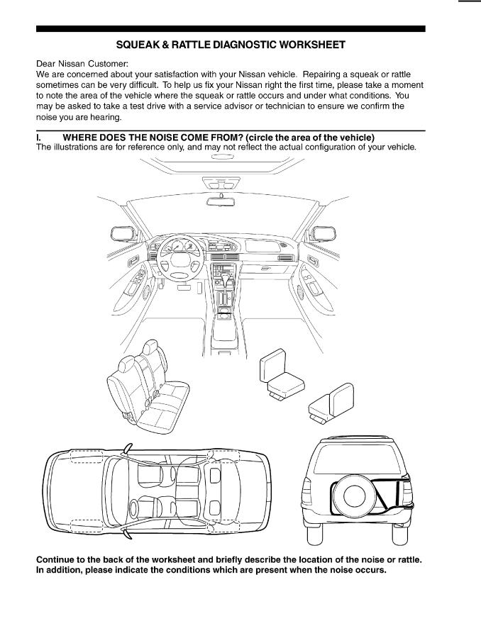
Diagnostic Worksheet |
AIS00610 |
PIIB0723E
Revision: 2005 March |
BL-10 |
2005 X-Trail |
SQUEAK AND RATTLE TROUBLE DIAGNOSES
A
B
C
D
E
F
G
H
BL
J
K
L
M
SBT844
Revision: 2005 March |
BL-11 |
2005 X-Trail |
HOOD
HOOD
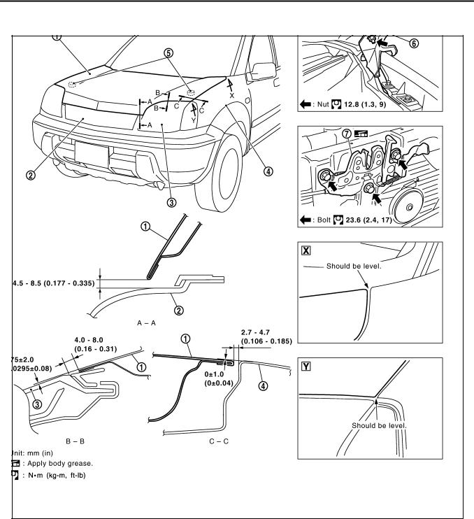
Fitting Adjustment
PFP:65100
AIS005NB
PIIB1609E
1. |
Hood assembly |
2. |
Front grille |
3. |
Headlamp |
4. |
Front fender |
5. |
Bumper rubber |
6. |
Hood hinge |
7.Hood lock assembly
LONGITUDINAL AND LATERAL CLEARANCE ADJUSTMENT
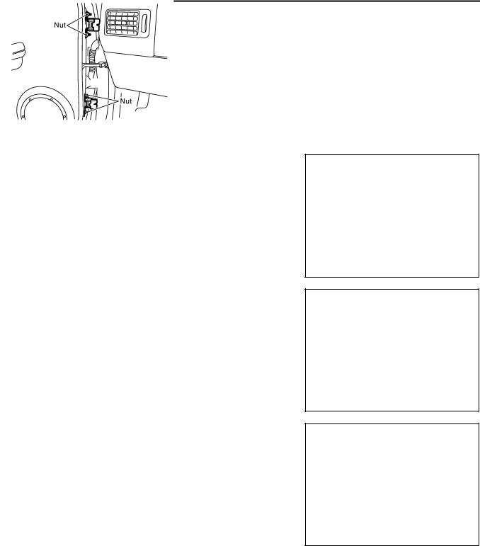
1.Remove hood lock assembly, loosen the hood hinge nuts and close the hood.
2.Adjust the lateral and longitudinal clearance, and open the hood to tighten the hood hinge mounting bolts to the specified torque.
3.Install the hood lock temporarily, and align the hood striker and lock so that the centers of striker and lock become vertical viewed from the front, by moving the hood lock laterally.
4.Tighten hood lock mounting bolts to the specified torque.
Revision: 2005 March |
BL-12 |
2005 X-Trail |

HOOD
CAUTION:
Adjust right/left clearance between hood and each part to the following specification.
Hood and front grille (A–A) |
: Less than 1.0 mm (0.04 in) |
Hood and fender (C–C) |
: Less than 1.0 mm (0.04 in) |
FRONT END HEIGHT ADJUSTMENT
A
B
1.Remove the hood lock and adjust the height by rotating the bumper rubber until the hood becomes 1 to1.5
mm (0.04 to 0.059 in) lower than the fender.
2.Temporarily tighten the hood lock, and position it by engaging it with the hood striker. Check the lock and striker for looseness, and tighten the hood lock mounting bolts to the specified torque.
C
D
E
F
G
H
BL
J
K
L
M
Revision: 2005 March |
BL-13 |
2005 X-Trail |

HOOD
SURFACE HEIGHT ADJUSTMENT
1.Remove hood lock, and adjust the surface height difference of hood, fender and headlamp according to the fitting standard dimension, by rotating RH and LH bumper rubbers.
2.Install hood lock temporarily, and move hood lock laterally until the centers of striker and lock become vertical when viewed from the front.
3.Make sure that the hood lock secondary latch is properly engaged with the secondary striker with hood's own weight.
4.Make sure that the hood lock primary latch is securely engaged with the hood striker with hood's own weight by dropping hood from approx. 200 mm(7.87 in) height.
CAUTION:
Do not drop hood from a height of 300 mm (11.81 in) or more.
5.Move hood lockup and down until striker smoothly engages the lock when the hood is closed.
PIIB1082E
6. When pulling the hood opener lever gently, make sure that front
end of the hood rises by approximately 20 mm (0.79 in) and that hood striker and hood lock primary latch is disengaged. Also make sure that hood opener returns to the original position.
7. After adjustment, tighten lock bolts to the specified torque.
Revision: 2005 March |
BL-14 |
2005 X-Trail |

HOOD
Removal and Installation of Hood Assembly
AIS005NC
A
B
C
D
E
F
G
H
BL
J
K
L
M
SIIA0154E
REMOVAL
1.Disconnect washer hose at the connection.
2.Remove hood hinge mounting nuts on the hood and then the hood assembly.
CAUTION:
Operate with two workers, because of its heavy weight.
INSTALLATION
Install in the reverse order of removal.
CAUTION:
●Before installing hood hinge, apply anticorrosive agent onto the mounting surface of the vehicle body.
●After installing, perform hood fitting adjustment. Refer to BL-12, "Fitting Adjustment" .
Revision: 2005 March |
BL-15 |
2005 X-Trail |

HOOD
Removal and Installation of Hood Lock Control |
AIS005ND |
PIIB1610E
1. Hood lock assembly |
2. Hood lock cable |
3. Cable clip |
Radiator core support sealing rub-
4. 5. Harness clip 6. Hoodledge upper ber
REMOVAL
1.Remove hood lock cable from hood lock and clip of upper portion of radiator core support and hood ledge.
2.Remove fender protector. Refer to EI-20, "FENDER PROTECTOR" .
3.Remove dash side finisher. Refer to EI-36, "BODY SIDE TRIM" .
4.Remove attaching screw and then the hood opener.
5.Remove dash panel grommet and pull hood lock cable toward the passenger compartment.
NOTE:
When pulling the cable, be careful not to strip or scratch the PIIB1611E outer surface.
Revision: 2005 March |
BL-16 |
2005 X-Trail |

HOOD
INSTALLATION
1.Pass hood lock cable through the opening while keeping the winding radius 100 mm (3.94 in) or larger.
2.After confirming that the grommet is properly positioned, push the grommet securely into the hole.
3.Apply sealant to the area on the grommet indicated with the * mark.
4.Connect cable securely to the lock.
5.After connection, confirm proper adjustment and operation for both hood lock and hood opener.
PIIA0173E
PIIA3552E
A
B
C
D
E
F
G
Hood Lock Control Inspection
CAUTION:
If the hood lock cable is bent or deformed, replace it.
1.Make sure that the hood lock secondary latch is securely engaged with the secondary striker with hood's own weight.
2.Make sure that the hood lock primary latch is securely engaged with the hood striker with hood's own weight by dropping it from approx 200 mm (7.87 in) height.
CAUTION:
Do not drop hood from a height of 300 mm (11.81 in) or more.
H
AIS005NE
BL
J
K
L
PIIB1082E
3.When pulling hood opener lever gently, make sure that front end of the hood rises by approximately 20
mm (0.79 in) and that hood striker and hood lock primary latch are disengaged. Also make sure that hood |
M |
||
|
|||
opener returns to the original position. |
|
||
4. Confirm hood lock is properly lubricated. If necessary, apply |
|
|
|
|
|
||
“body grease” at the point shown in the figure. |
|
||
PIIA3550E
Revision: 2005 March |
BL-17 |
2005 X-Trail |
FRONT FENDER
FRONT FENDER
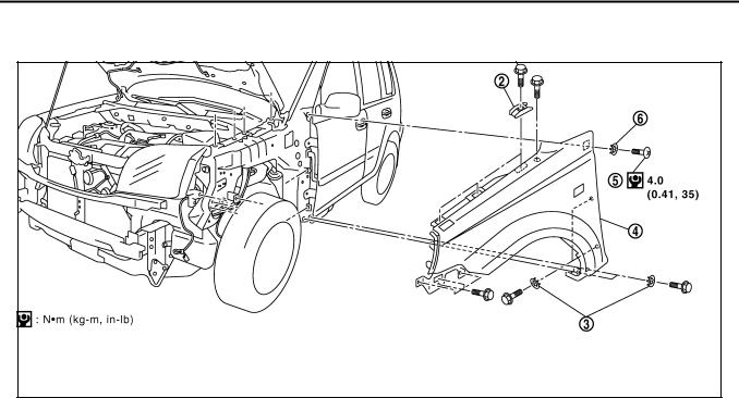
Removal and Installation
PFP:63100
AIS0061L
PIIB1612E
1. |
Bolt |
2. |
Stiffener |
3. |
Spring washer |
4. |
Front fender |
5. |
TORX bolt (T20) |
6. |
Spring washer |
REMOVAL
1.Remove the front bumper. Refer to EI-14, "FRONT BUMPER" .
2.Remove the turn signal lamp. Refer to LT-22, "Removal and Installation of Front Turn Signal Lamp" .
3.Remove the front fender protector. Refer to EI-20, "FENDER PROTECTOR" .
4.Remove the mounting bolt and remove the front fender.
CAUTION:
While removing use a shop cloth to protect body from damaging.
INSTALLATION
Install in the reverse order of removal.
CAUTION:
●After installing, apply touch-up paint (the body color) onto the head of the front fender mounting bolts.
●After installing, check front fender adjustment. Refer to BL-12, "Fitting Adjustment" and BL-19, "Fitting Adjustment" .
Revision: 2005 March |
BL-18 |
2005 X-Trail |

|
DOOR |
|
|
|
|
|
|
|
|
|
|
DOOR |
PFP:80100 |
||||
Fitting Adjustment |
|
|
|
A |
|
AIS005NF |
|||||
|
|
|
|
|
B |
|
|
|
|
|
|
|
|
|
|
|
C |
|
|
|
|
|
D |
|
|
|
|
|
E |
|
|
|
|
|
F |
|
|
|
|
|
G |
|
|
|
|
|
H |
|
|
|
|
|
|
|
|
|
|
|
BL |
|
|
|
|
|
|
|
|
|
|
|
J |
|
|
PIIA3652E |
|
||
FRONT DOOR |
|
|
|
K |
|
|
|
|
|
||
Longitudinal Clearance and Surface Height Adjustment at Front End |
|
|
|
|
|
1. Remove fender protector. Refer to EI-20, "FENDER PROTECTOR" . |
|
|
|
L |
|
2.Working from the inside the fender, loosen hinge mount bolts on the body. Lift rear end of the front door to adjust clearance and surface difference properly.
REAR DOOR |
M |
Longitudinal Clearance and Surface Height Adjustment at Front End |
|
1.Remove upper and lower garnishes on the center pillar. Refer to EI-36, "BODY SIDE TRIM" .
2.Loosen mounting bolts from outside of vehicle, mounting nuts from inside of vehicle. Open rear door. Raise rear end of it to adjust.
STRIKER ADJUSTMENT
Adjust striker until it is parallel to the lock engagement direction.
PIIA0555E
Revision: 2005 March |
BL-19 |
2005 X-Trail |
DOOR
Removal and Installation of Front Door |
AIS005NG |
CAUTION:
●When removing and installing the front door assembly, support the door with a jack and cloth to protect the door and body.
●When removing and installing front door assembly, be sure to carry out the fitting adjustment. Refer to BL-19, "Fitting Adjustment" .
●Operate with two workers, because of its heavy weight.
●After installing, apply touch-up paint (the body color) onto the head of the hinge mounting nuts.
●Check the hinge rotating part for poor lubrication. If necessary, apply “body grease”.
●Check front door open/close operation after installation.
REMOVAL
1.Grommet is pulled out, and the front door harness connector is detached.
PIIB1369E
2.Remove the mounting bolts of the check link on the vehicle.
PIIA6020E
3.Remove the door-side hinge mounting nuts, and remove the door assembly.
 : 20.6 N·m (2.1 kg-m, 15 ft-lb)
PIIB1337E
INSTALLATION
Install in the reverse order of removal.
Removal and Installation of Rear Door |
AIS005NH |
CAUTION:
●When removing and installing the rear door assembly, support the door with a jack and cloth to protect the door and body.
●When removing and installing rear door assembly, be sure to carry out the fitting adjustment. Refer toBL-19, "Fitting Adjustment" .
●Check the hinge rotating part for poor lubrication. If necessary, apply “body grease”.
Revision: 2005 March |
BL-20 |
2005 X-Trail |
DOOR
●After installing, apply touch-up paint (the body color) onto the head of the hinge mounting nuts.
● Operate with two workers, because of its heavy weight. |
A |
●Check rear door open/close operation after installation.
REMOVAL |
B |
1.Grommet is pulled out, and the rear door harness connector is detached.
C
D
E
PIIB1370E
2.Remove the mounting bolts of the check link on the vehicle.
F
G
H
PIIA6022E
BL
3.Remove the door-side hinge mounting nuts, and remove the door assembly.
J
 : 20.6 N·m (2.1 kg-m, 15 ft-lb)
K
L
PIIB1336E
INSTALLATION
M
Install in the reverse order of removal.
Revision: 2005 March |
BL-21 |
2005 X-Trail |

DOOR
Door Weatherstrip |
AIS005NI |
SIIA0157E
REMOVAL
1.Remove the mounting bolts of the check link on the vehicle. Refer to BL-20, "Removal and Installation of Front Door" or BL-20, "Removal and Installation of Rear Door" .
2.Remove the weatherstrip clips and remove weatherstrip.
CAUTION:
After removal, do not pull strongly on the weatherstrip.
INSTALLATION
Install in the reverse order of removal.
Revision: 2005 March |
BL-22 |
2005 X-Trail |

POWER DOOR LOCK SYSTEM
POWER DOOR LOCK SYSTEM |
PFP:24814 |
|||
Component Parts and Harness Connector Location |
|
|
A |
|
AIS005X9 |
||||
|
|
|
|
B |
|
|
|
|
|
|
|
|
|
C |
|
|
|
|
D |
|
|
|
|
E |
|
|
|
|
F |
|
|
|
|
G |
|
|
|
|
H |
|
|
|
|
|
|
|
|
|
BL |
|
|
|
|
|
|
|
|
|
J |
|
|
|
|
K |
|
|
|
|
L |
|
|
|
|
M |
|
|
PIIB1463E |
|
System Description |
AIS005XA |
||
OPERATION |
|
|
|
Power is supplied at all times
●through 10A fuse [No. 26, located in the fuse block (J/B)]
●to smart entrance control unit terminal 49,
●through 40A fusible link (letter B , located in the fusible link and fuse box)
●to smart entrance control unit terminal 51.
Ground is supplied at all times
●to smart entrance control unit terminal 43 and 64
●through grounds M27 and M70.
Revision: 2005 March |
BL-23 |
2005 X-Trail |

POWER DOOR LOCK SYSTEM
When ignition switch is in ON or START position, power is supplied
●through 10A fuse [No. 5, located in the fuse block (J/B)]
●to smart entrance control unit terminal 27.
When key switch is in INSERTED position, power is supplied
●through 10A fuse [No. 28, located in the fuse block (J/B)]
●through key switch terminal 1
●through key switch terminal 2 and
●to smart entrance control unit terminal 25.
DOOR LOCK/UNLOCK SWITCH (POWER WINDOW MAIN SWITCH) OPERATION
When power window main switch (door lock/unlock switch) is in LOCK position, ground is supplied
●to smart entrance control unit terminal 5
●through power window main switch (door lock/unlock switch) terminal 17
●through power window main switch (door lock/unlock switch) terminal 19 and
●through grounds M27 and M70.
Then all doors are locked.
When power window main switch (door lock/unlock switch) is in UNLOCK position, ground is supplied
●to smart entrance control unit terminal 4
●through power window main switch (door lock/unlock switch) terminal 18
●through power window main switch (door lock/unlock switch) terminal 19 and
●through grounds M27 and M70.
Then all doors are unlocked.
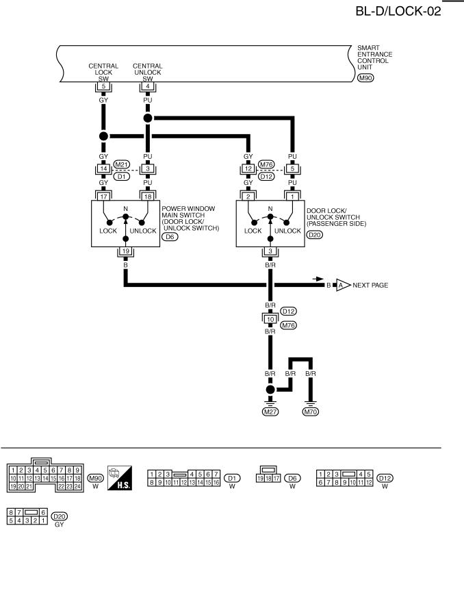
DOOR LOCK/UNLOCK SWITCH (PASSENGER SIDE) OPERATION
When door lock/unlock switch (passenger side) is in LOCK position, ground is supplied
●to smart entrance control unit terminal 5
●through door lock/unlock switch (passenger side) terminal 2
●through door lock/unlock switch (passenger side) terminal 3 and
●through grounds M27 and M70.
Then all doors are locked.
When door lock/unlock switch (passenger side) is in UNLOCK position, ground is supplied
●to smart entrance control unit terminal 4
●through door lock/unlock switch (passenger side) terminal 1
●through door lock/unlock switch (passenger side) terminal 3 and
●through grounds M27 and M70.
Then all doors are unlocked.
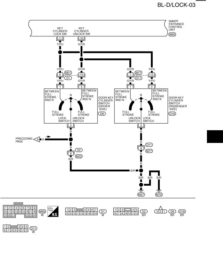
DOOR KEY CYLINDER SWITCH OPERATION Driver Side
When door key cylinder switch (driver side) is in LOCK position, ground is supplied
●to smart entrance control unit terminal 11
●through door key cylinder switch (driver side) terminal 1
●through door key cylinder switch (driver side) terminal 2 and
●through grounds M27 and M70.
Then all doors are locked.
When door key cylinder switch (driver side) is in UNLOCK position, ground is supplied
●to smart entrance control unit terminal 10
●through door key cylinder switch (driver side) terminal 3
●through door key cylinder switch (driver side) terminal 2 and
●through grounds M27 and M70.
Then all doors are unlocked.
Revision: 2005 March |
BL-24 |
2005 X-Trail |

POWER DOOR LOCK SYSTEM
Passenger Side
When door key cylinder switch (passenger side) is in LOCK position, ground is supplied
●to smart entrance control unit terminal 11
●through door key cylinder switch (passenger side) terminal 3
●through door key cylinder switch (passenger side) terminal 2 and
●through grounds M27 and M70.
Then all doors are locked.
When door key cylinder switch (passenger side) is in UNLOCK position, ground is supplied
●to smart entrance control unit terminal 10
●through door key cylinder switch (passenger side) terminal 1
●through door key cylinder switch (passenger side) terminal 2 and
●through grounds M27 and M70.
Then all doors are unlocked.
KEY REMINDER SYSTEM
●If the ignition key is in the ignition key cylinder and doors are open, setting lock/unlock switch, lock knob,
key or multi-remote controller to “LOCK” locks the door once but then immediately unlocks all doors.
A
B
C
D
E
F
G
H
BL
J
K
L
M
Revision: 2005 March |
BL-25 |
2005 X-Trail |
POWER DOOR LOCK SYSTEM
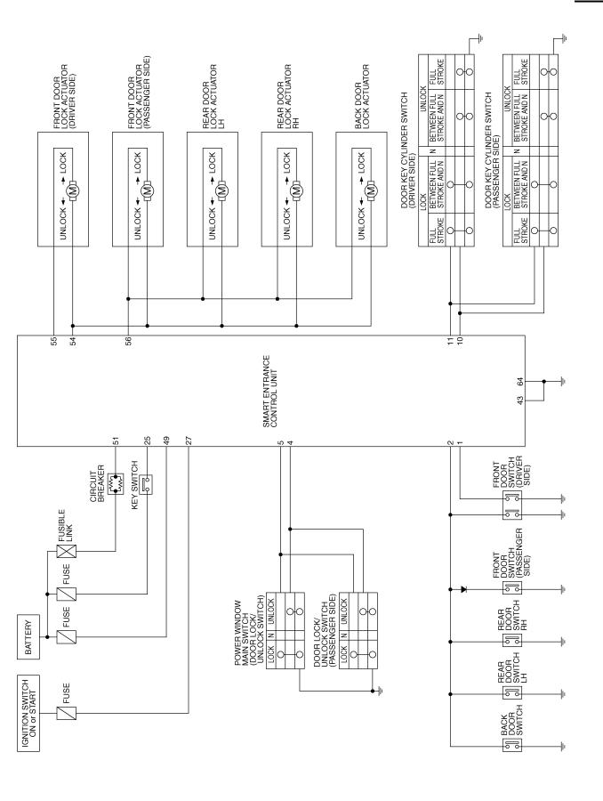
Schematic
AIS005XB
TIWB0043E
Revision: 2005 March |
BL-26 |
2005 X-Trail |

POWER DOOR LOCK SYSTEM
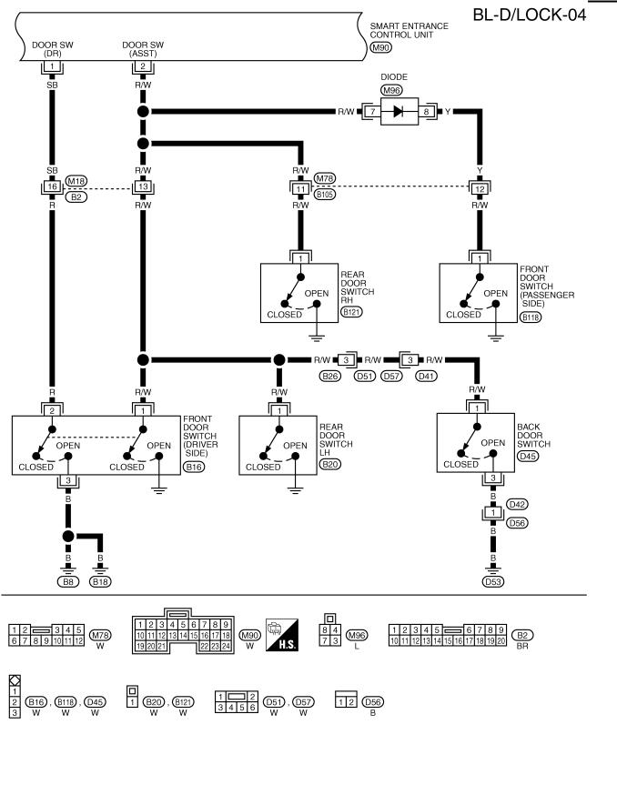
Wiring Diagram — D/LOCK —
AIS005XC
A
B
C
D
E
F
G
H
BL
J
K
L
M
TIWA0550E
Revision: 2005 March |
BL-27 |
2005 X-Trail |
POWER DOOR LOCK SYSTEM
TIWB0044E
Revision: 2005 March |
BL-28 |
2005 X-Trail |
POWER DOOR LOCK SYSTEM
A
B
C
D
E
F
G
H
BL
J
K
L
M
TIWB0045E
Revision: 2005 March |
BL-29 |
2005 X-Trail |
POWER DOOR LOCK SYSTEM
TIWB0046E
Revision: 2005 March |
BL-30 |
2005 X-Trail |
Loading...