


 Loading...
E SUSPENSION
SECTION RSU
REAR SUSPENSION
CONTENTS
A
B
C
D
RSU
PRECAUTIONS ......................................................... |
2 |
Caution .................................................................... |
2 |
PREPARATION .......................................................... |
3 |
Special Service Tools [SST] .................................... |
3 |
Commercial Service Tools ....................................... |
3 |
NOISE, VIBRATION AND HARSHNESS (NVH) |
|
TROUBLESHOOTING ............................................... |
4 |
NVH Troubleshooting Chart .................................... |
4 |
REAR SUSPENSION ASSEMBLY ............................ |
5 |
On-Vehicle Inspection and Service ......................... |
5 |
STRUT INSPECTION .......................................... |
5 |
Wheel Alignment Inspection .................................... |
5 |
DESCRIPTION ..................................................... |
5 |
PREMINARY CHECK .......................................... |
5 |
CAMBER INSPECTION ....................................... |
5 |
TOE-IN ................................................................. |
5 |
Component .............................................................. |
7 |
Removal and Installation ......................................... |
8 |
REMOVAL ............................................................ |
8 |
INSTALLATION .................................................... |
9 |
COIL SPRING AND STRUT .................................... |
10 |
Removal and Installation ....................................... |
10 |
REMOVAL .......................................................... |
10 |
INSTALLATION .................................................. |
10 |
Disassembly and Assembly ................................... |
11 |
DISASSEMBLY ................................................... |
11 |
INSPECTION AFTER DISASSEMBLY ............... |
11 |
ASSEMBLY ........................................................ |
12 |
FRONT PARALLEL LINK ........................................ |
13 |
Removal and Installation ....................................... |
13 |
REMOVAL .......................................................... |
13 |
INSPECTION AFTER REMOVAL ...................... |
13 |
INSTALLATION .................................................. |
13 |
REAR PARALLEL LINK .......................................... |
14 |
Removal and Installation ....................................... |
14 |
REMOVAL .......................................................... |
14 |
INSPECTION AFTER REMOVAL ...................... |
14 |
INSTALLATION .................................................. |
14 |
RADIUS ROD ........................................................... |
15 |
Removal and Installation ....................................... |
15 |
REMOVAL .......................................................... |
15 |
INSPECTION AFTER REMOVAL ...................... |
15 |
INSTALLATION .................................................. |
15 |
STABILIZER BAR .................................................... |
16 |
Removal and Installation ....................................... |
16 |
REMOVAL .......................................................... |
16 |
INSPECTION AFTER REMOVAL ...................... |
16 |
INSTALLATION .................................................. |
16 |
REAR SUSPENSION MEMBER .............................. |
17 |
Removal and Installation ....................................... |
17 |
REMOVAL .......................................................... |
17 |
INSPECTION AFTER REMOVAL ...................... |
17 |
INSTALLATION .................................................. |
17 |
SERVICE DATA AND SPECIFICATIONS (SDS) ..... |
18 |
Wheel Alignment (Unladen) ................................... |
18 |
Wheelarch Height (Unladen*) ................................ |
18 |
F
G
H
I
J
K
L
M
Revision: 2005 March |
RSU-1 |
2005 X-Trail |

PRECAUTIONS
PRECAUTIONS
Caution
PFP:00001
AES000XA
●When installing rubber bushings, final tightening must be performed under unladen conditions with tires on ground. Oil will shorten the life of rubber bushings. Be sure to wipe off any spilled oil.
–Unladen conditions mean that fuel, engine coolant and lubricant are full. A spare tire, a jack, hand tools and mats are in designated positions.
●After servicing suspension parts, be sure to check wheel alignment.
●Self-lock nuts are not reusable. Always use new ones when installing. Since new self-lock nuts are preoiled, tighten as they are.
Revision: 2005 March |
RSU-2 |
2005 X-Trail |
|
|
PREPARATION |
|
|
||
|
|
|
|
|
|
|
PREPARATION |
|
PFP:00002 |
|
A |
||
Special Service Tools [SST] |
|
|
|
|
||
|
AES000XB |
|
|
|||
|
|
|
|
|
|
|
|
Tool number |
|
|
|
|
B |
|
(Kent-Moore No.) |
|
Description |
|
||
|
Tool name |
|
|
|
|
|
|
|
|
|
|
|
C |
|
|
|
|
|
|
|
|
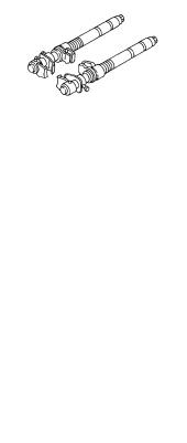
ST35652000 |
|
|
|
|
|
|
( – ) |
|
Disassembling and assembling strut |
|
|
|
|
Strut attachment |
|
|
|
|
D |
|
|
|
|
|
|
|
|
|
ZZA0807D |
|
|
|
|
|
|
|
RSU |
|||
|
|
|
|
|
|
|
Commercial Service Tools |
|
AES000XC |
|
|||
|
|
|
|
|
|
|
|
Tool name |
|
Description |
|
|
|
|
|
|
|
|
|
F |
|
|
|
● Removing wheel nuts |
|
||
|
|
|
|
|
||
|
|
|
● Removing torque member fixing |
|
|
|
|
Power tool |
|
bolts |
|
G |
|
|
|
● Removing stabilizer component |
|
|||
|
|
|
|
|
||
|
|
|
parts. |
|
|
|
|
|
PBIC0190E |
● Removing strut assembly lower side |
|
H |
|
|
|
|
|
|
||
|
|
|
|
|
|
I |
|
Spring compressor |
|
Removing coil spring |
|
||
|
|
|
|
|||
|
|
S-NT717 |
|
|
|
J |
|
|
|
|
|
||
|
|
|
|
|
|
K |
|
|
|
|
|
|
|
|
|
|
|
|
|
L |
|
|
|
|
|
|
M |
Revision: 2005 March |
RSU-3 |
2005 X-Trail |

NOISE, VIBRATION AND HARSHNESS (NVH) TROUBLESHOOTING
NOISE, VIBRATION AND HARSHNESS (NVH) TROUBLESHOOTING
NVH Troubleshooting Chart
PFP:00003
AES000XD
Use chart below to help you find the cause of the symptom. If necessary, repair or replace these parts.
|
|
|
|
|
|
|
|
|
|
|
|
|
|
|
|
|
|
|
|
PRinNVHsection |
RFDinNVHsection |
andRAXin RSU sections |
|
WTinNVHsection |
|
WTinNVHsection |
RAXinNVHsection |
|
BRinNVHsection |
PSinNVHsection |
Reference page |
|
RSU-7 |
|
RSU-11 |
|
— |
— |
|
— |
|
RSU-7 |
|
|
RSU-5 |
|
RSU-16 |
|
|||||||||||||
|
|
|
|
|
|
|
|
|
|
|
|
|
|
|
|
|
|
|
|
|
|
|
|
|
|
|
|
|||
|
|
|
|
|
|
|
|
|
|
|
|
|
|
|
|
|
|
|
|
|
|
NVH |
|
|
|
|
|
|
|
|
|
|
|
|
|
|
|
|
|
|
|
|
|
|
|
|
|
|
|
|
|
|
|
|
|
|
|
|
|
|
|
|
|
|
|
|
|
|
|
|
|
|
|
|
|
|
|
|
|
|
|
|
|
|
|
|
|
|
|
|
||
Possible cause and Suspected parts |
|
installation,Improperlooseness |
|
damagedeformation,Strut or deflection |
|
mountingorBushingdeterioration |
interferenceParts |
|
fatigueSpring |
|
loosenessSuspension |
|
alignmentwheelIncorrect |
fatiguebarStabilizer |
|
SHAFTPROPELLER |
DIFFERENTIAL |
REARANDAXLEREARSUSPENSION |
|
TIRES |
|
WHEELSROAD |
SHAFTDRIVE |
|
BRAKES |
STEERING |
||||
|
|
|
|
|
|
|
|
|
|
|
|
|
|
|
|
|
|
|
|
|
|
|
|
|
|
|
|
|||
|
|
|
|
|
|
|
|
|
|
|
|
|
|
|
|
|
|
|
|
|
|
|
|
|
|
|
|
|
|
|
|
|
|
Noise |
× |
|
× |
|
× |
× |
× |
|
× |
|
|
|
|
|
× |
|
× |
× |
× |
|
× |
× |
× |
× |
|
|
|
|
|
|
|
|
|
|
|
|
|
|
|
|
|
|
|
|
|
|
|
|
|
|
|
|
|
|
|
|
|
|
|
|
|
Shake |
× |
|
× |
|
× |
× |
|
|
× |
|
|
|
|
|
|
× |
|
× |
× |
|
× |
|
× |
× |
× |
|
|
|
|
|
|
|
|
|
|
|
|
|
|
|
|
|
|
|
|
|
|
|
|
|
|
|
|
|
|
|
|
|
|
|
|
Vibration |
× |
|
× |
|
× |
× |
× |
|
|
|
|
|
|
|
|
× |
|
× |
× |
|
|
|
× |
|
|
× |
|
Symptom |
Rear suspension |
|
|
|
|
|
|
|
|
|
|
|
|
|
|
|
|
|
|
|
|
|
|
|
|
|
|
|
|
|
|
Shimmy |
× |
|
× |
|
× |
× |
|
|
|
|
|
× |
|
|
|
|
|
× |
× |
|
× |
|
|
× |
|
× |
|
||
|
|
|
|
|
|
|
|
|
|
|
|
|
|
|
|
|
|
|
|
|
|
|
|
|
|
|
|
|
|
|
|
|
|
Judder |
× |
|
× |
|
× |
|
|
|
|
|
|
|
|
|
|
|
|
|
× |
× |
|
× |
|
× |
|
× |
|
|
|
|
|
|
|
|
|
|
|
|
|
|
|
|
|
|
|
|
|
|
|
|
|
|
|
|
|
|
|
|
|
|
|
Poor quality ride or |
× |
|
× |
|
× |
× |
× |
|
|
× |
|
× |
|
|
|
× |
× |
|
× |
|
|
|
|
|
|
||
|
|
|
handling |
|
|
|
|
|
|
|
|
|
|
|
|
|
|
|
||||||||||||
|
|
|
|
|
|
|
|
|
|
|
|
|
|
|
|
|
|
|
|
|
|
|
|
|
|
|
|
|
|
|
|
|
|
|
|
|
|
|
|
|
|
|
|
|
|
|
|
|
|
|
|
|
|
|
|
|
|
|
|
|
|
× : Applicable |
|
|
|
|
|
|
|
|
|
|
|
|
|
|
|
|
|
|
|
|
|
|
|
|
|
|
|
|
||
Revision: 2005 March |
RSU-4 |
2005 X-Trail |
REAR SUSPENSION ASSEMBLY
REAR SUSPENSION ASSEMBLY |
PFP:55020 |
On-Vehicle Inspection and Service |
AES000XE |
Make sure that the mounting conditions (looseness, back lash) of each of the components and the component conditions (wear, damage) are normal.
STRUT INSPECTION
Check for oil leakage, damage, and breakage of installation positions.
Wheel Alignment Inspection |
AES000XF |
DESCRIPTION
A
B
C
Measure wheel alignment under unladen conditions. |
D |
||
NOTE: |
|||
|
|||
“Unladen conditions” mean that fuel, engine coolant, and lubricant are full. A spare tire, a jack, hand tools and |
|
|
|
|
|
||
mats are in designated positions. |
RSU |
||
|
|
||
PREMINARY CHECK
Check the following:
1.Tires for improper air pressure and wear.
2.Road wheels for runout. Refer to WT-4, "ROAD WHEEL" .
3.Wheel bearing axial end play. Refer to RAX-5, "WHEEL BEARING INSPECTION" .
4.Strut operation.
5.Each of mounting points of axle housing and suspension for looseness and deformation.
F
G
6.Each of rear parallel link, front parallel link, suspension member, radius rod and strut for cracks, deformation, and other damage.
7.Vehicle height under unladen conditions (posture).
CAMBER INSPECTION
H
I
●Measure camber of both right and left wheels with a suitable alignment gauge.
●Adjust in accordance with the following procedures.
Camber : Refer to RSU-18, "SERVICE DATA AND SPECIFICATIONS (SDS)" .
●If camber is not within the specification, inspect and replace any damaged or worn rear suspension parts.
J
K
L
SRA096A
TOE-IN
M
Measure toe-in using following procedure. If out of the specification, inspect and replace any damaged or worn rear suspension parts.
WARNING:
●Always perform the following procedure on a flat surface.
●Make sure that no person is in front of vehicle before pushing it.
1.Bounce rear of vehicle up and down to stabilize the vehicle height (posture).
2.Push vehicle straight ahead about 5 m (16 ft).
3.Put a mark on base line of the tread (rear side) of both tires at the same height of hub center. These are measuring points.
SEIA0362E
Revision: 2005 March |
RSU-5 |
2005 X-Trail |

REAR SUSPENSION ASSEMBLY
4.Measure distance “A” (rear side).
5.Push vehicle slowly ahead to rotate wheels 180° degrees (1/2 turn).
NOTE:
If the wheels have rotated more than 180° degrees (1/2 turn), start this procedure again from the beginning. Do not push the vehicle backward.
6.Measure distance “B” (front side).
Total toe-in : Refer to RSU-18, "SERVICE DATA AND
SPECIFICATIONS (SDS)" .
7.If toe-in is not within the specification, adjust by turning the adjusting bolt of rear parallel link.
CAUTION:
When adjusting toe-in, set the both sides to the same values.
SEIA0363E
SEIA0126E
Revision: 2005 March |
RSU-6 |
2005 X-Trail |
Loading...