

Page 1

DRIVER INFORMATION SYSTEM
K ELECTRICAL
A
B
SECTION DI
DRIVER INFORMATION SYSTEM
CONTENTS
PRECAUTIONS .......................................................... 3
Precautions for Supplemental Rest raint System
(SRS) “AIR BAG” and “SEAT BELT PRE-TEN-
SIONER” .................................................................. 3
Wiring Diagrams and Trouble Diagnosis .................. 3
COMBINATION METERS ........................................... 4
System Description .................................................. 4
UNIFIED METER CONTROL UNIT ...................... 4
POWER SUPPLY AND GROUND CIRCUIT ........ 4
ODO/TRIP METER, CLOCK AND AMBIENT
TEMPERATURE INDICATOR ............................... 4
SPEEDOMETER ................................................... 4
TACHOMETER ..................................................... 5
WATER TEMPERATURE GAUGE ............... ......... 5
FUEL GAUGE ....................................................... 5
AMBIENT TEMPERATURE INDICATOR .............. 5
CAN Communication ................................................ 6
SYSTEM DESCRIPTION ...................................... 6
CAN COMMUNICATION UNIT ............................. 6
Arrangement of Combination Meter ......................... 7
Component Parts and Harness Connector Location ..... 8
Schematic ................................................................ 9
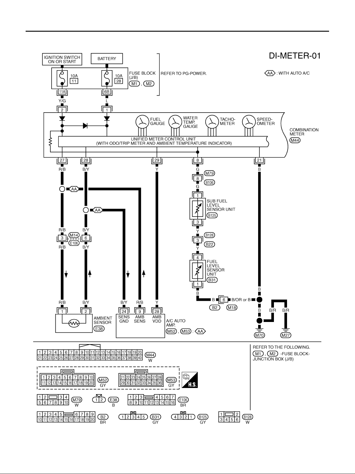
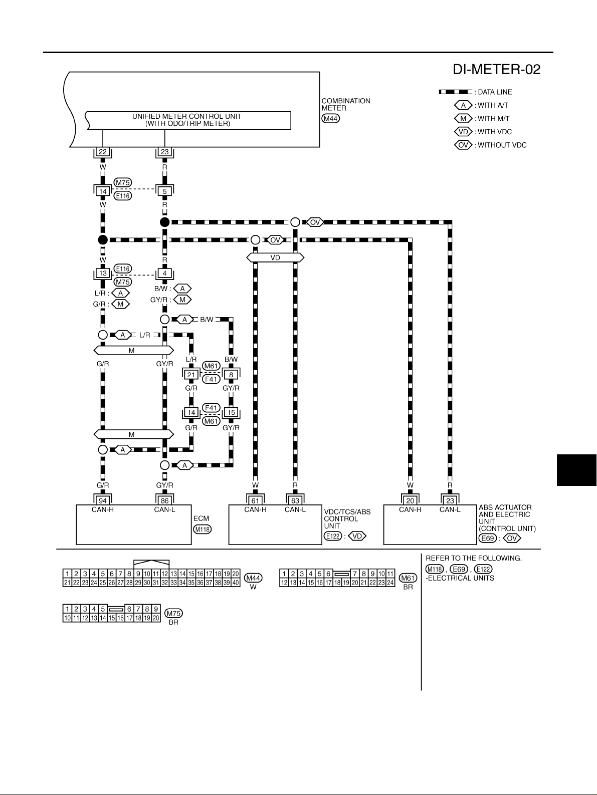
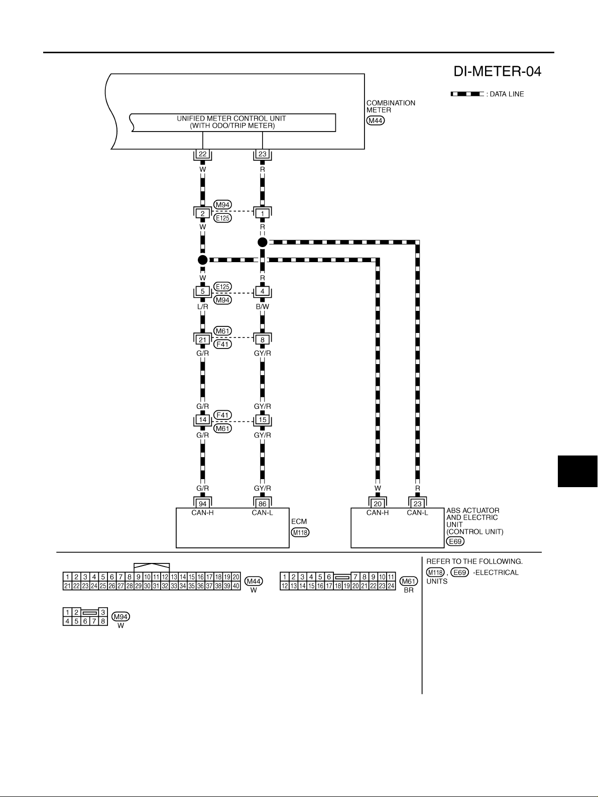
Wiring Diagram — METER — ................................ 10
AWD MODELS .................................................... 10
2WD MODELS .................................................... 12
Terminals and Reference Value for Combination
Meter .............................. ........................................ 14
Self-Diagnosis Mode of Combination Meter ........... 14
SELF-DIAGNOSIS FUNCTION .......................... 14
OPERATION PROCEDURE ............................... 14
Trouble Diagnosis .................................................. 15
HOW TO PROCEED WITH TROUBLE DIAGNO-
SIS ...................................................................... 15
PRELIMINARY CHECK ...................................... 15
SYMPTOM CHART ............................................. 16
Power Supply and Ground Circuit Inspection ........ 16
Vehicle Speed Signal Inspection (With VDC) ......... 17
Vehicle Speed Signal Inspection (Without VDC) .... 17
Engine Speed Signal Inspection ............................ 17
Engine Coolant Temperature Signal Inspection ..... 18
Fuel Level Sensor Inspection .................................18
The Fuel Gauge Pointer Fluctuates, Indicator
Wrong Value or Varies ............................................ 19
The Fuel Gauge Does Not Move to FULL Position ...20
Ambient Temperature Signal Inspection [Without
Auto A/C] ........................... ....... ...... ........................20
Ambient T emperature Signal Inspection [With Auto
A/C] .............................. ...... ....... ...... ....... ...... ....... .... 22
Electrical Components Inspection ..........................23
FUEL LEVEL SENSOR UNIT CHECK ................23
AMBIENT SENSOR CHECK ...............................23
Removal and Installation for Combination Meter .... 24
REMOVAL ........................................................... 24
INSTALLATION ...................................................24
Disassembly and Assembly for Combination Meter ...24
DISASSEMBLY ................................................... 24
ASSEMBLY ......................................................... 24
WARNING LAMPS .................................................... 25
Schematic .................... ....................................... ....25
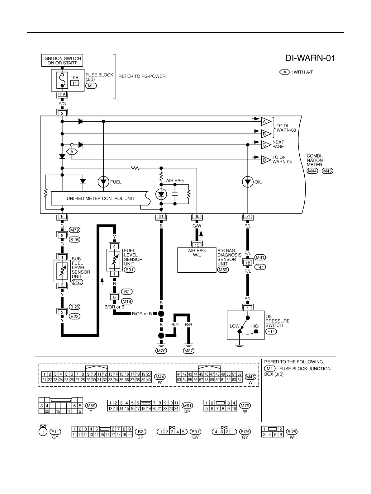
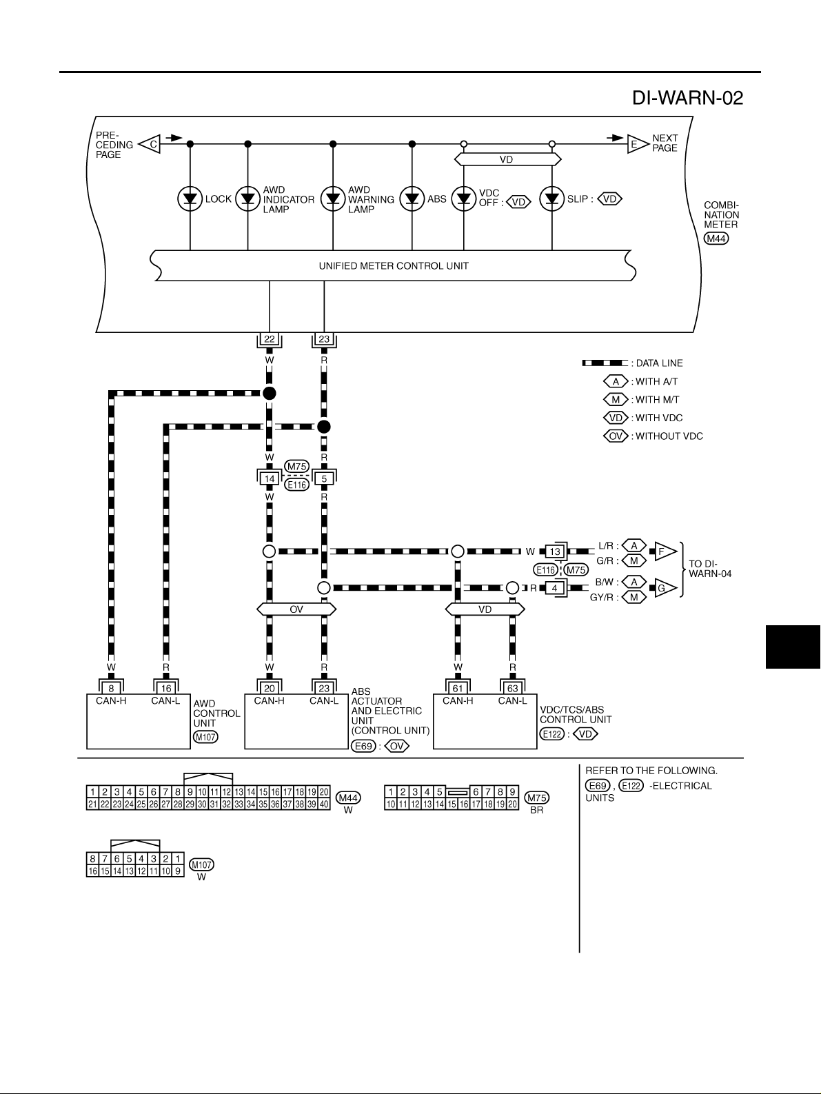
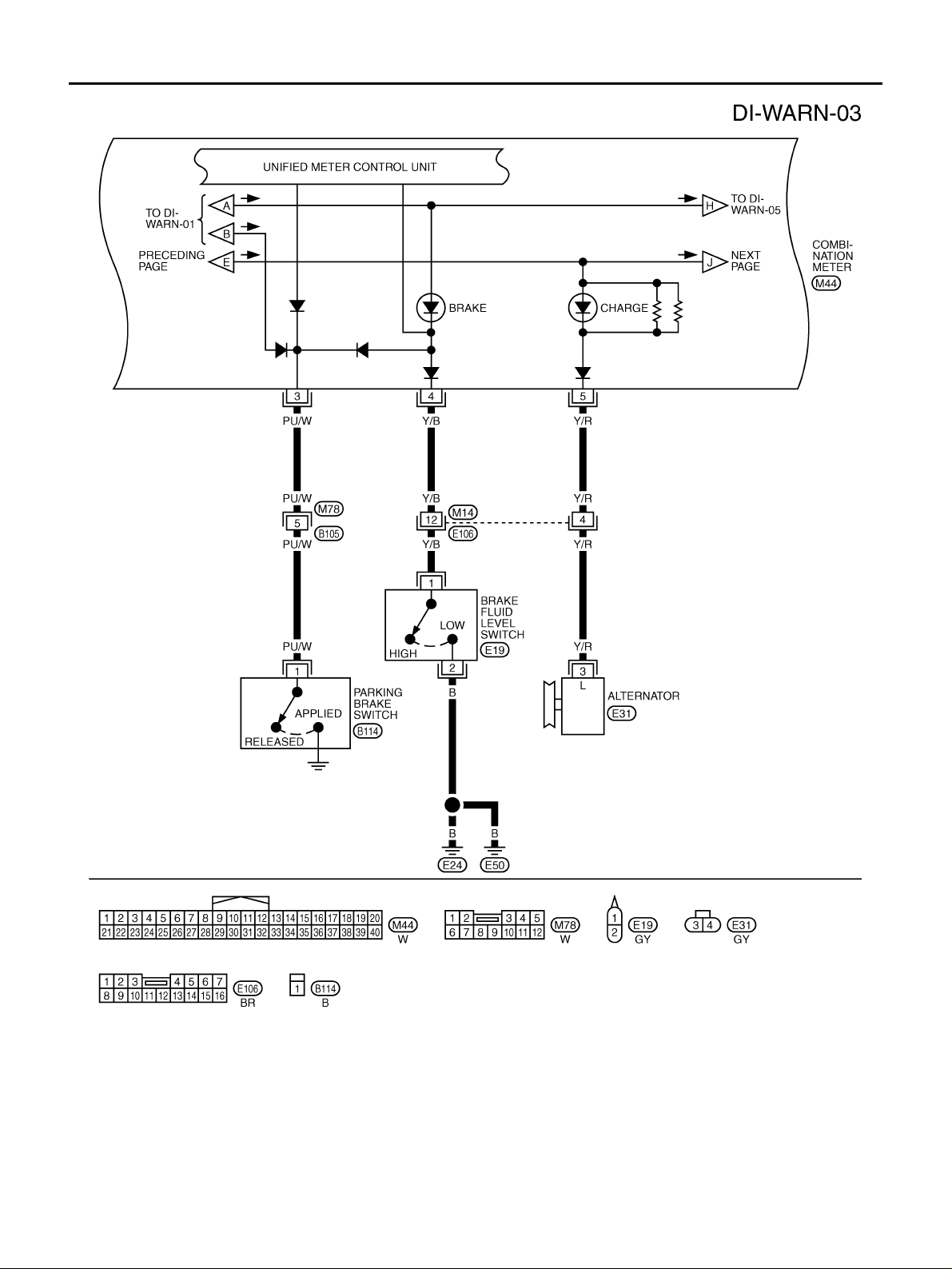
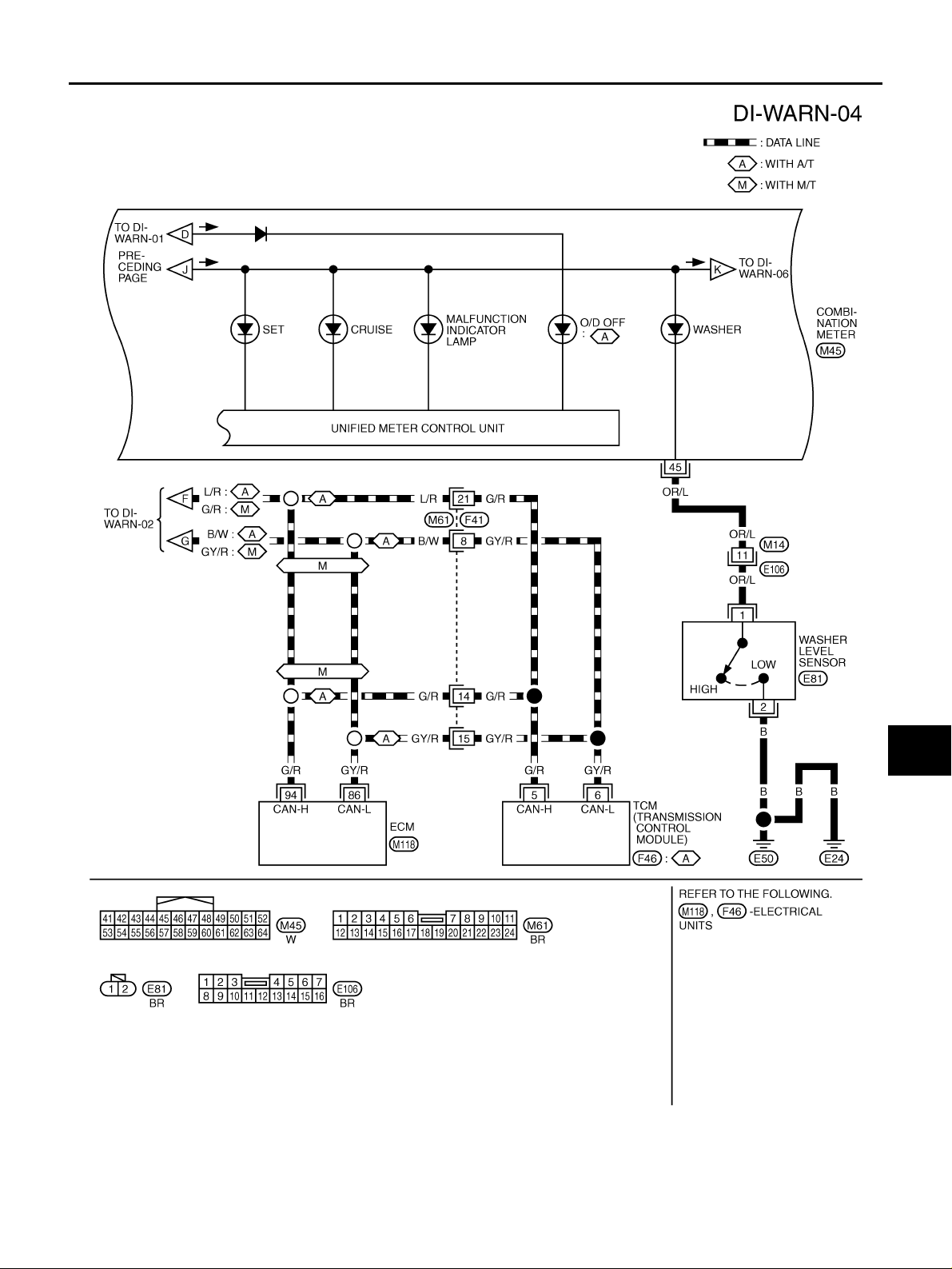
Wiring Diagram — WARN — .................................. 26
AWD MODELS ....................................................26
2WD MODELS ....................................................32
Electrical Components Inspection ..........................38
OIL PRESSURE SWITCH CHECK ..................... 38
DIODE CHECK ...................................................38
A/T INDICATOR ................................ ....... ...... ....... .... 39
Wiring Diagram — AT/IND — ................................. 39
AWD MODELS ....................................................39
2WD MODELS ....................................................40
A/T Indicator Does Not Illuminate ........................... 41
WARNING CHIME ..................................................... 42
System Description .................................................42
POWER SUPPLY AND GROUND CIRCUIT ....... 42
IGNITION KEY WARNING CHIME ..................... 42
LIGHT WARNING CHIME ................................... 42
SEAT BELT WARNING CHIME ...........................42
Component Parts and Harness Connector Location ...43
Schematic .................... ....................................... ....44
Wiring Diagram — CHIME — .................................45
T erminals and Reference Value for Smart Entrance
C
D
E
F
G
H
I
J
DI
L
M
Revision: 2005 March 2005 X-Trail
DI-1
Page 2

Control Unit .............................................................48
Trouble Diagnosis ...................................................48
HOW TO PROCEED WITH TROUBLE DIAGNO-
SIS ............................... ........................................48
SYMPTOM CHART .............................................48
Power Supply and Ground Circuit Inspection .........48
Front Door Switch (Driver Side) Inspection ............49
Lighting Switch Input Signal Inspection ..................51
Key Switch Insert Signal Inspection ........................51
Seat Belt Buckle Switch Input Signal Inspection
[Without Power Seat] ..............................................52
Seat Belt Buckle Switch Input Signal Inspection
[With Power Seat] ...................................................54
CLOCK ......................................................................56
Wiring Diagram — CLOCK — .................................56
Revision: 2005 March 2005 X-Trail
DI-2
Page 3

PRECAUTIONS
PRECAUTIONS PFP:00011
Precautions for Supplemental Restraint System (SRS) “AIR BAG” and “SEAT BELT PRE-TENSIONER”
AKS00B9V
A
The Supplemental Rest raint System such as “AIR BAG” and “SEAT BELT PRE-TENSIONER”, used al ong
with a front seat belt, helps to redu ce th e risk or se verit y of i njury to the driv er and front passenge r for ce rtain
types of col lision. Information necessary to service the system safely is includ ed in the SRS a nd SB section of
this Service Manual.
WARNING:
● To avoid rendering the SRS inopera tive, whi ch could incr ease the risk of pe rsonal injury or death
in the event of a collision which would result in air bag inflation, all maintenance must be performed by an authorized NISSAN/INFINITI dealer.
● Improper maintenance, inc luding incorrect removal and installation of the SRS, can lead to per-
sonal injury ca use d by unintentional ac tiv atio n o f the s ys t em . F or re mo va l of Spiral Cable and Ai r
Bag Module, see the SRS sec tion.
● Do not use electrical test equ ipment o n any circu it related to the SRS unless in structed to in this
Service Manual. SRS wiring harnesses can be identified by yellow and/or orange harnesses or
harness connectors.
Wiring Diagrams and Trouble Diagnosis AKS00B9W
When reading wiring diagrams, refer to the following:
● GI-14, "How to Read Wiring Diagrams" in GI section
● PG-2, "POWER SUPPLY ROUTING" for power distribution circuit in PG section
When performing trouble diagnosis, refer to the following:
● GI-10, "HOW TO FOLLOW TEST GROUPS IN TROUBLE DIAGNOSES" in GI section
● GI-26, "How to Perform Efficient Diagnosis for an Electrical Incident" in GI section
B
C
D
E
F
G
H
I
DI
J
L
M
Revision: 2005 March 2005 X-Trail
DI-3
Page 4
COMBINATION METERS
COMBINATION METERS PFP:24814 System Description AKS00B9X
UNIFIED METER CONTROL UNIT
● Speedometer, odo/trip meter, tachometer, fuel gauge and water temperature gauge are controlled by the
unified meter control unit, which is built into the combination meter.
● Digital meter is adopted for odo/trip meter*.
*The record of the odo meter is kept even if the battery cable is disconnected. The record of the trip meter
is erased when the battery cable is disconnected.
● Meter/gauge and odo/trip meter segments can be checked in diagnosis mode.
POWER SUPPLY AND GROUND CIRCUIT
Power is supplied at all time s
● through 10 A fuse [No. 28, located in the fuse block (J/B)]
● to combination meter terminal 1.
With the ignition switch in the ON or START position, power is supplied
● through 10 A fuse [No. 11, located in the fuse block (J/B)]
● to combination meter terminal 2.
Ground is supplied
● to combination meter terminal 21
● through grounds M27 and M70.
ODO/TRIP METER, CLOCK AND AMBIENT TEMPERATURE INDICATOR
● The vehicle speed s ignal and the memory sig nals from the meter memory c ircuit are processed by t he
combination meter and the mileage is displayed.
● Ambient temperature indicator indicates signal from ambient sensor processed by the combination meter.
How to Change The Display
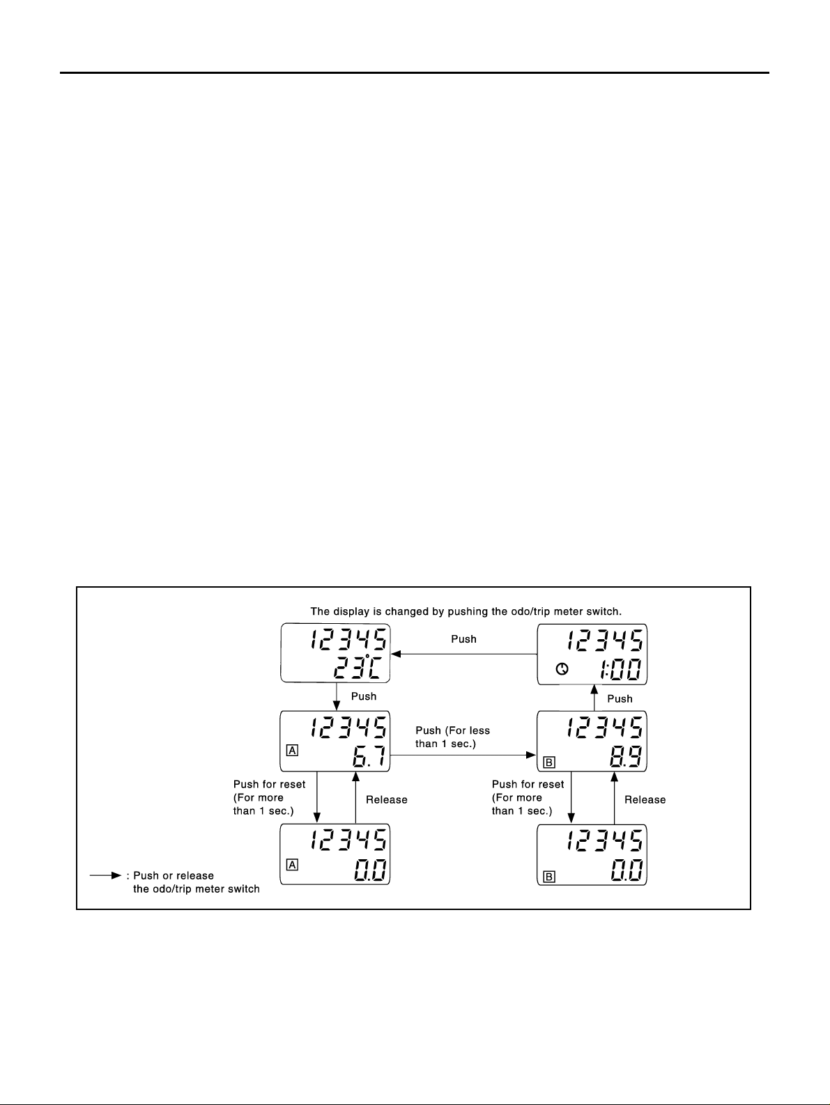
Depressing the odo/trip meter switch toggles the mode in the following order.
SKIA8917E
● The odo/tr ip mete r displ a y mo de togg li ng an d tr ip di spla y r es ett i ng can be ide nt i fie d b y th e a mo unt o f t ime
that elapses from pressing the odo/trip meter switch to releasing it.
● When resetting with trip A displayed, only trip A display is reset. (The same way for trip B.)
SPEEDOMETER
VDC/TCS/ABS control unit [with VDC] or ABS actuator and electric unit (control unit) [without VDC] provides a
vehicle speed signal to the combination meter for the speedometer with CAN communication line.
Revision: 2005 March 2005 X-Trail
DI-4
Page 5

COMBINATION METERS
TACHOMETER
The tachometer indicates engine speed in revol uti on s pe r minu te (rpm).
ECM provides an engine speed signal to combination meter for tachometer with CAN communicati on line.
A
WATER TEMPERATURE GAUGE
The water temperature gauge indicates the engine coolant temperature.
ECM provides an engine coolant temperature signal to combination meter for water temperature gauge with
CAN communication line.
FUEL GAUGE
The fuel gauge indicates the approximate fuel level in the fuel tank.
The fuel gauge is regulated by a variable ground signal supplied
● from grounds M2 7 an d M70
● through terminals 1 and 4 of the fuel level sensor unit
● through terminals 3 and 1 of the sub fuel level sensor unit and
● to combination meter terminal 8 for the fuel gauge.
AMBIENT TEMPERATURE INDICATOR
The ambient temperature is indicated by the signal from ambient sensor.
Combination meter inputs voltage conversed from resistance which ambient sensor detects.
Indication range is between -30 an d 5 5 °C (-22 a nd 13 1 °F). When ambient temperature is less than -30 °C (22 °F) or more than 55 °C (13 1 °F ), di splay shows “--- °C”. When in dica ted te mpera tu re bec omes less tha n 3
°C (37 °F), ambient temperature indicator flashes as a sign of warning.
Without Auto A/C
Power is supplied
● through combination meter terminal 27
● to ambient sensor terminal 1.
Ground is supplied
● to combination meter terminal 28
● through ambient sensor terminal 2.
Signal is supplied
● through ambient sensor terminal 1
● to combination meter terminal 27.
B
C
D
E
F
G
H
I
J
DI
With Auto A/C
Power is supplied
● through A/C auto amp. terminal 9
● to ambient sensor terminal 1.
Ground is supplied
● to combination meter terminal 28 and A/C auto amp. terminal 24
● through ambient sensor terminal 2.
And combination meter receives ambient sensor signal from ambient sensor
● through ambient sensor terminal 1
● to combination meter terminal 27.
NOTE:
Combination m eter distinguishes whet her or not combinatio n meter terminal 29 rece ives voltage (Auto A/C
recognition signal) from A/C auto amp. terminal 28. If the terminal receives, combination meter discerns as
auto A/C.
Indication When Turning Ignition Switch OFF
● In a case that temperature detected by ambient sensor is higher than indicated temperature before turn-
ing ignition switch off.
– In a case of more than 3.5 hou rs afte r turning ignition switc h off, tem pe r at ure det ec ted by am bi en t se ns or
is indicated when turning ignition switch on.
Revision: 2005 March 2005 X-Trail
DI-5
L
M
Page 6

COMBINATION METERS
– In a case of less then 3.5 hours after turning ignition switch off, temperature at the time of turning ignition
switch off is indicated.
● In a case that temperature detected by ambient sensor is lower than indicated temperature before turning
ignition switch off.
– Temperature detected by ambient sensor is indicated when turning ignition switch on.
Indication During Running
Though temperature detected by ambient sensor temporarily changed, indicating temperature continentally
indicates.
● In a case that temperature detected by ambient sensor is higher than indicated temperature.
– If vehicle speed is more than 20 km/h (13 MPH), elevation of indicating temperature is limited according to
the speed until temperature detected by ambient sensor is indicated.
NOTE:
Vehicle speed 20 km/h (13 MPH): 256 sec., 25 km/h (16 MPH): 238 sec., 35 km/h (22 MPH): 200 sec., 50
km/h (31 MPH): 144 sec., 65 km/h (40 MPH): 88 sec., more than 80 km/h (50 MPH): 32 sec.
– If vehicle speed is more than 20 km/h (13 MPH), and that temperature detected by ambient sensor
becomes 8 °C (46 °F) more than indicating temperature, indicating temperature will be elevated unit the
degree becomes sa me as temperature detecte d by ambient sensor with limitin g elevation of indicating
temperature 1 °C par a minute.
– If vehicle speed is less th an 20 km/h (13 MPH) , indicating temperature is con tinually kept.
● In a case that temperature detected by ambient sensor is lower than indicated temperature.
– Temperature detected by ambient sensor is indicated during running.
CAN Communication AKS00BQ7
SYSTEM DESCRIPTION
CAN (Controller Area N et w ork ) is a s eri al co mm u nic a tio n l ine for real time appl ic ati on . It is an on-vehicle multiplex communi catio n lin e wit h high da t a comm unic ation speed and ex cellen t er ror det ecti on ab ilit y. Many electronic control u nits are eq uipped o nto a ve hicle, a nd eac h control unit sh ares info rmation and link s with ot her
control units duri ng operation (not independent). In CAN communicatio n, control units ar e connected wi th 2
communication lines (CAN H line, CAN L line) allowing a high rate of information transmission with less wiring.
Each control unit transmits/receives data but selectively reads required data only.
CAN COMMUNICATION UNIT
Refer to LAN-16, "CAN Communication Unit" in “LAN SYSTEM”.
Revision: 2005 March 2005 X-Trail
DI-6
Page 7
COMBINATION METERS
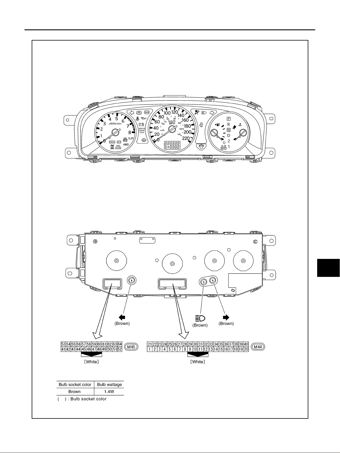
Arrangement of Combination Meter AKS00BA1
A
B
C
D
E
F
G
DI
H
I
J
L
M
SKIB0505E
Revision: 2005 March 2005 X-Trail
DI-7
Page 8
COMBINATION METERS
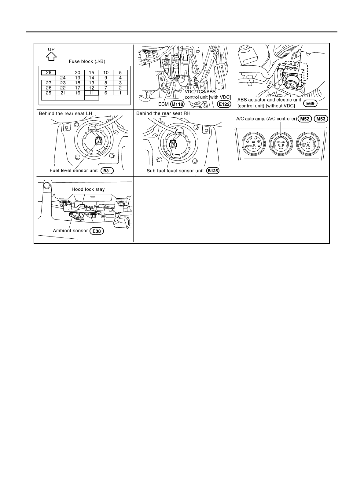
Component Parts and Harness Connector Location AKS00BA0
SKIB0506E
Revision: 2005 March 2005 X-Trail
DI-8
Page 9
COMBINATION METERS
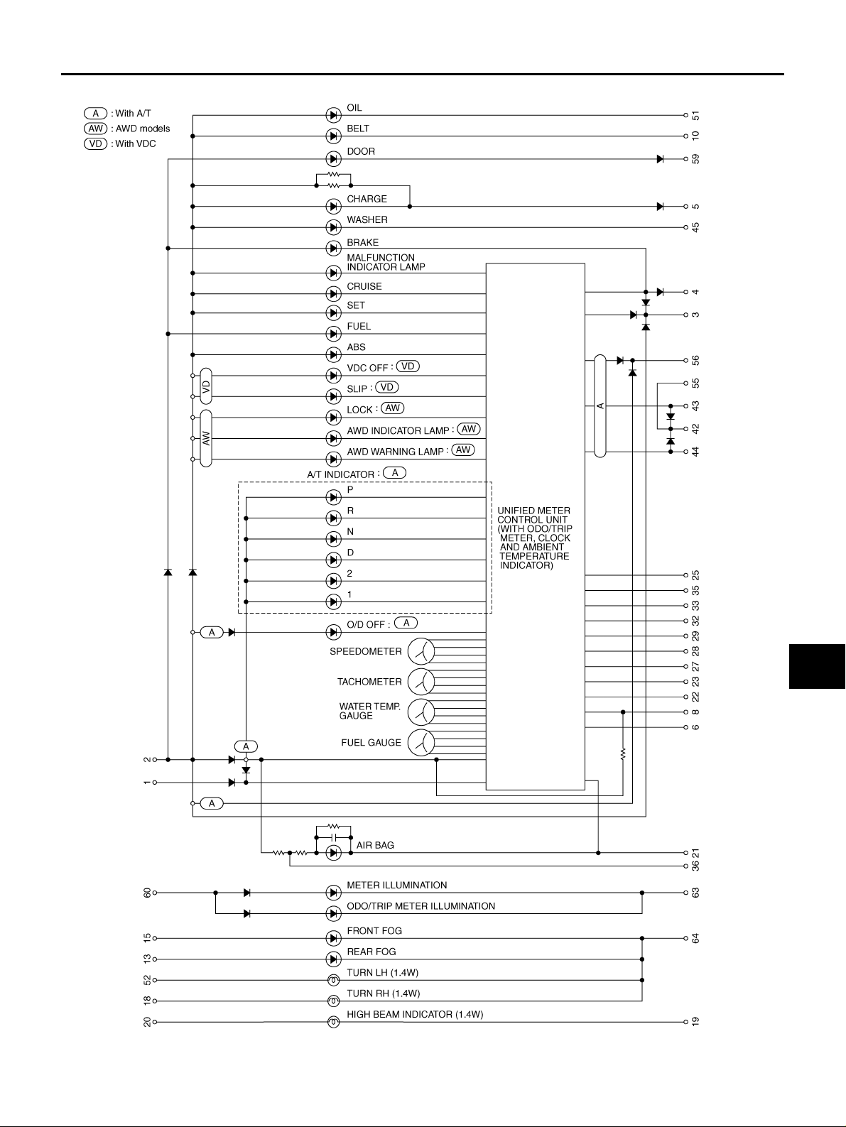
Schematic AKS00BA2
A
B
C
D
E
F
G
DI
H
I
J
L
M
TKWB0170E
Revision: 2005 March 2005 X-Trail
DI-9
Page 10
COMBINATION METERS
Wiring Diagram — METER — AKS00BA3
AWD MODELS
TKWB0171E
Revision: 2005 March 2005 X-Trail
DI-10
Page 11
COMBINATION METERS
A
B
C
D
E
F
G
DI
H
I
J
L
M
TKWB0172E
Revision: 2005 March 2005 X-Trail
DI-11
Page 12
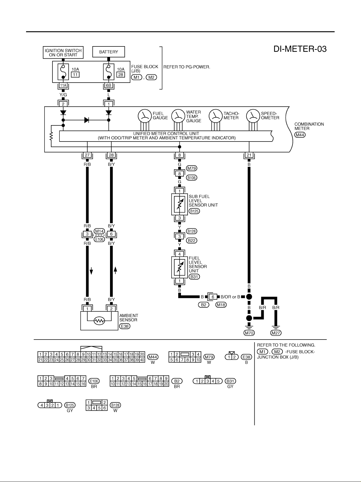
2WD MODELS
COMBINATION METERS
TKWB0173E
Revision: 2005 March 2005 X-Trail
DI-12
Page 13
COMBINATION METERS
A
B
C
D
E
F
G
DI
H
I
J
L
M
TKWB0174E
Revision: 2005 March 2005 X-Trail
DI-13
Page 14
COMBINATION METERS
Terminals and Reference Value for Combination Meter AKS00BA6
Terminal
No.
1 L Battery power supply OFF — Battery voltage
2 Y/G I gni t ion switch (ON ) ON — Battery voltage
8 G Fuel level sensor signal — —
21 B Ground ON — Approx. 0 V
22 W CAN-H — — —
23 R C AN-L — — —
27 R/B Ambient sensor signal — —
28 B/Y Ambient sensor ground — — —
*1
29
NOTE:
*1:With auto A/C
Wire
Color
Y Auto A/C recog ni tion signal ON — Approx . 5 V
Item
Ignition
switch
Condition
Operation or condition
Reference Value
Refer to DI-23, "
SOR UNIT CHECK" .
Refer to DI-23, "
CHECK"
FUEL LEVEL SEN-
AMBIENT SENSOR
Self-Diagnosis Mo de of Combi na tio n Mete r AKS00BA7
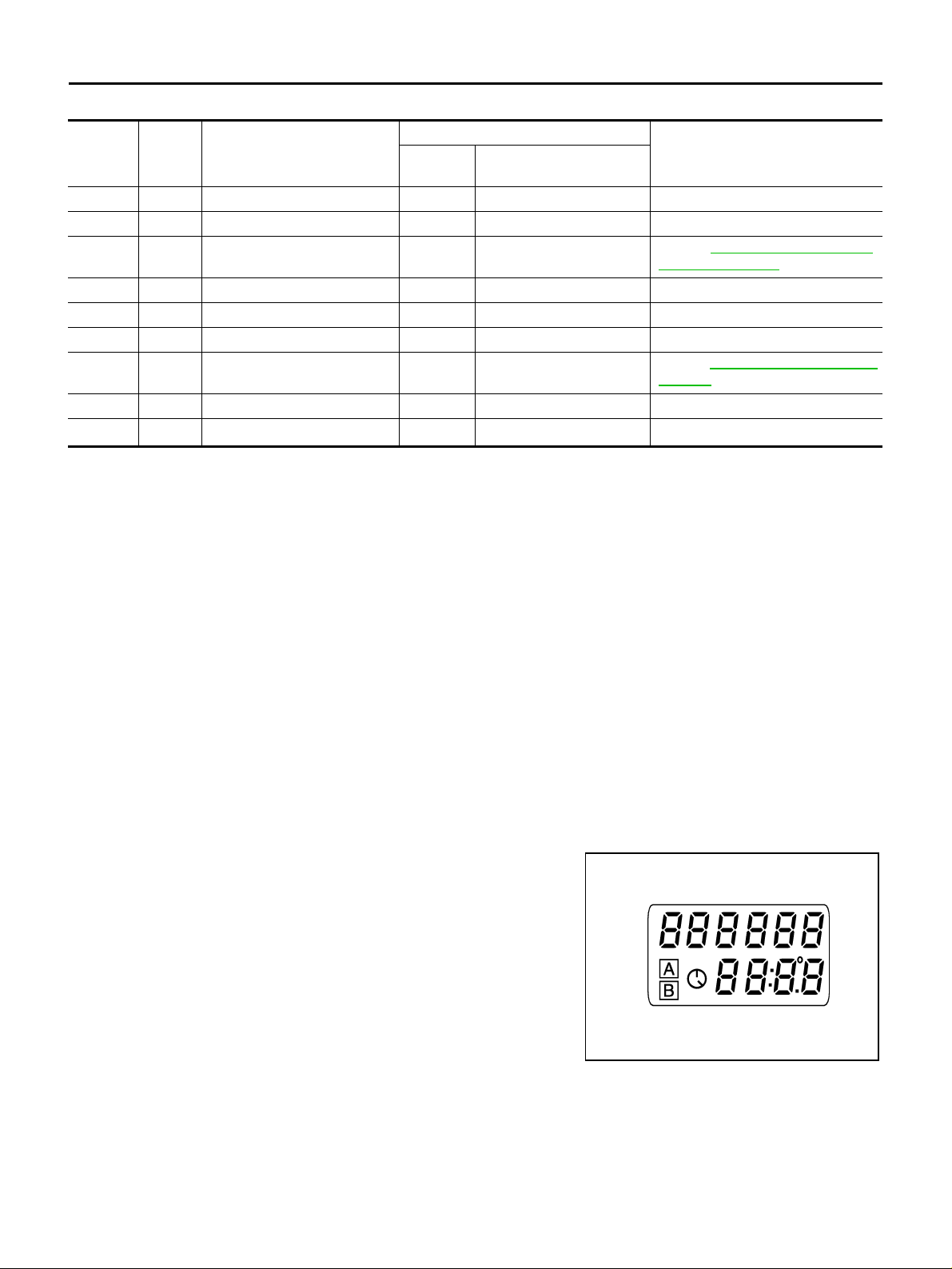
SELF-DIAGNOSIS FUNCTION
● Odo/trip meter segment operation can be checked in self-diagnosis mode.
● Meters/gauges can be checked in self-diagnosis mode.
OPERATION PROCEDURE
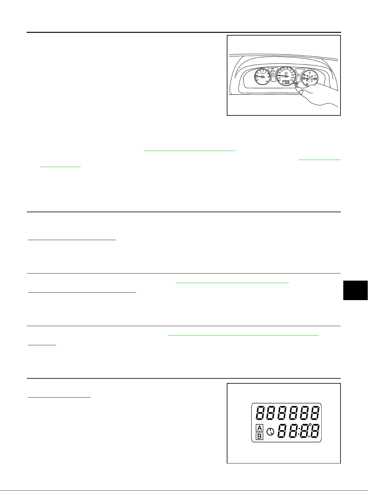
1. Turn the ignition switch ON, and switch the odo/trip meter to “trip A” or “trip B”.
NOTE:
If the diagnosis f unction is activated with the trip mete r A displayed , the mileage on the trip m eter A will
indicate 0.0 mile, but the actual trip mileage will be retained. (The same way for trip B.)
2. Turn ignition switch OFF.
3. While pushing the odo/trip meter switch, turn ignition switch ON again.
4. Make sure that the trip meter displays “0.0”.
5. Push the odo/trip meter switch at least 3 times. (Within 7 seconds after the ignition switch is turned ON.)
6. All the segmen ts on the odo/trip me ter illumi nate, and si multaneou sly the low -fuel warn ing lamp indi cato r
illuminates. At this time, the unified meter control unit is turned to diagnosis mode.
NOTE:
If any of the segments is not displayed, replace the combination
meter.
SKIA8920E
Revision: 2005 March 2005 X-Trail
DI-14
Page 15
COMBINATION METERS
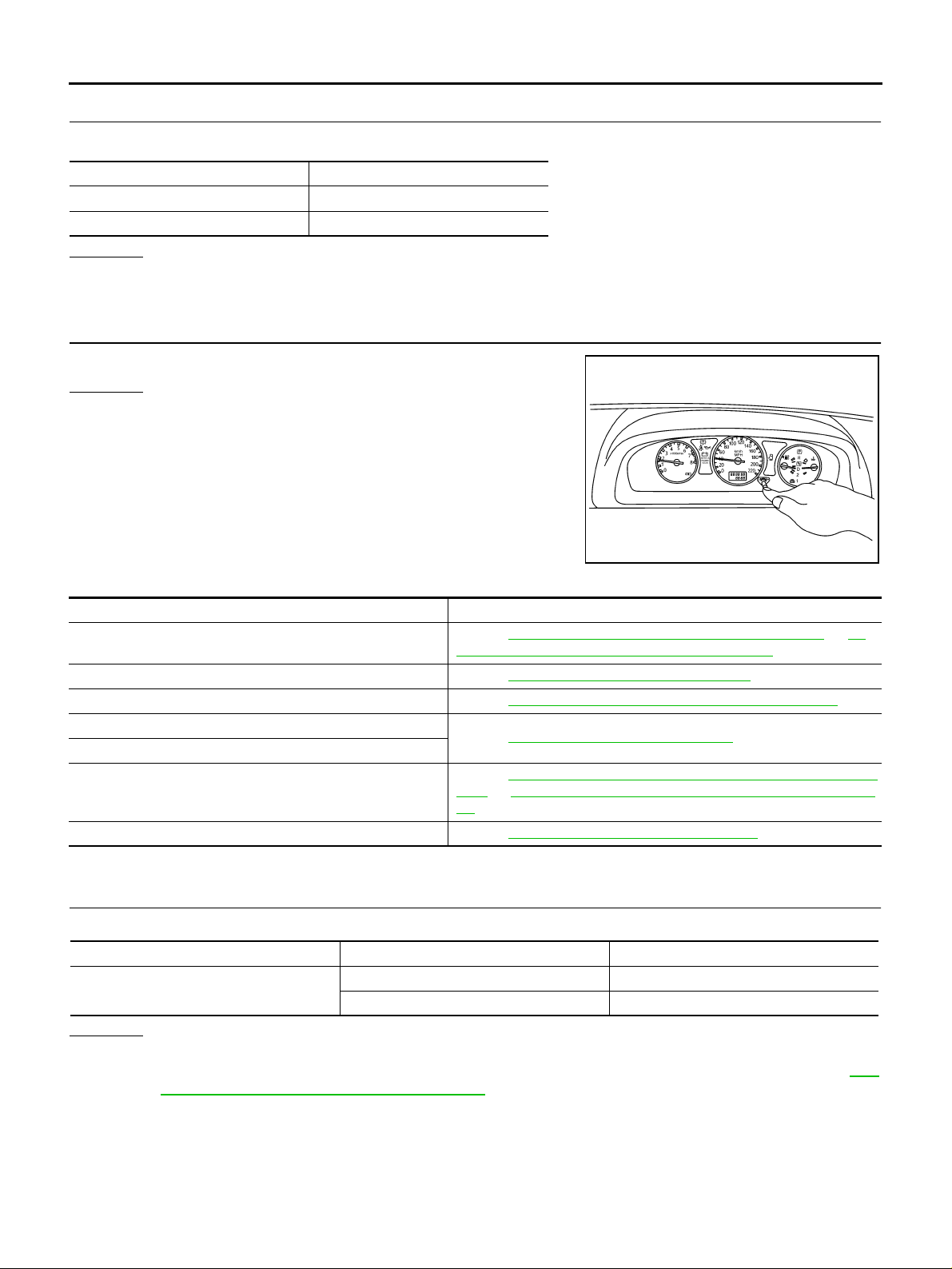
7. Push the odo /trip meter switch. Each meter/gauge sh ould indicate as shown in the figure while pushing odo/trip meter switch.
(At this time, the low-fuel warning lamp goes off.)
SKIB0507E
Trouble Diagnosis AKS00BQ6
HOW TO PROCEED WITH TROUBLE DIAGNOSIS
1. Confirm the symptom or customer complaint.
2. Perform preliminary check. Refer to DI-15, "
3. Accordin g to th e trouble diagnosi s c ha rt, re pair or re pl ac e th e c a us e o f sy m pto m . R efe r to DI-16, "
TOM CHART" .
4. Does the meter operate normally? If so, GO TO 5. If not, GO TO 2.
5. INSPECTION END
PRELIMINARY CHECK" .
SYMP-
A
B
C
D
E
F
PRELIMINARY CHECK
1. CHECK WARNING LAMP ILLUMINATION
1. Turn ignition switch ON.
2. Make sure that war ning lamp (such as MIL and oil pressure warning lamp) illuminat e.
Does warning lamp illuminate?
YES >> GO TO 2.
NO >> GO TO 3.
2. CHECK SELF-DIAGNOSIS OPERATION
Perform combination meter self-diagnosis. Refer to DI-14, "
Does self-diagnosis function operate?
YES >> GO TO 4.
NO >> GO TO 3.
SELF-DIAGNOSIS FUNCTION" .
3. CHECK POWER SUPPLY AND GROUND CIRCUIT
Check power supply and ground circuit. Refer to DI-16, "
OK or NG
OK >> Replace combination meter.
NG >> Repair as need.
Power Supply an d Ground Circuit Inspection" .
4. CHECK ODO/TRIP METER OPERATION
G
H
I
J
DI
L
M
Check segment display status of odo/trip meter.
Is the display normal?
YES >> GO TO 5.
NO >> Replace combination meter.
SKIA8920E
Revision: 2005 March 2005 X-Trail
DI-15
Page 16
COMBINATION METERS
5. CHECK LOW-FUEL WARNING LAMP ILLUMINATION
During inspection of low-fuel warning lamp, confirm illumination of low-fuel warning lamp.
Condition of odo/trip meter switch Fuel warning lamp
Pushed Does not illuminate.
Released Illuminates.
OK or NG
OK >> GO TO 6.
NG >> Replace combination meter.
6. CHECK METER CIRCUIT
Check indication of each meter/gauge in self-diagnosis mode.
OK or NG
OK >> INSPECTION END
NG >> Replace combination meter.
SKIB0507E
SYMPTOM CHART
Symptom Possible cause
Indication is irregular for the speedometer and odo/trip meter.
Tachometer indication is malfunction. Refer to DI-17, "
Water temperature gauge indication is malfunction. Refer to DI-18, "
Low-fuel warning lamp indication is irregular.
Fuel gauge indication is malfunction.
Ambient temperature indicator is malfunction.
A/T position indicator is malfunction. Refer to DI-41, "
Refer to DI-17, "
17, "Vehicle Speed Signal Inspection (Without VDC)" .
Refer to DI-18, "
Refer to DI-20, "
A/C]" or DI-22, "Ambient Temperature Signal Inspection [With Auto A/
C]" .
Vehicle Speed Signal Inspection (With VDC)" or DI-
Engine Speed Signal Inspection" .
Engine Coolant Temperature Signal Inspection" .
Fuel Level Sensor Inspection" .
Ambient Temperature Signal Inspection [Without Auto
A/T Indicator Does Not Illuminate" .
Power Supply and Ground Circuit Inspection AKS00BAA
1. CHECK FUSE
Check for blown combination meter fuses.
Unit Power source Fuse No.
Combination meter
OK or NG
OK >> GO TO 2.
NG >> If fuse is blown, be sure to eliminate cause of malfunction before installing new fuse. Refer to PG-
49, "FUSE BLOCK - JUNCTION BOX (J/B)" .
Battery 28
Ignition switch (ON) 11
Revision: 2005 March 2005 X-Trail
DI-16
Page 17
COMBINATION METERS
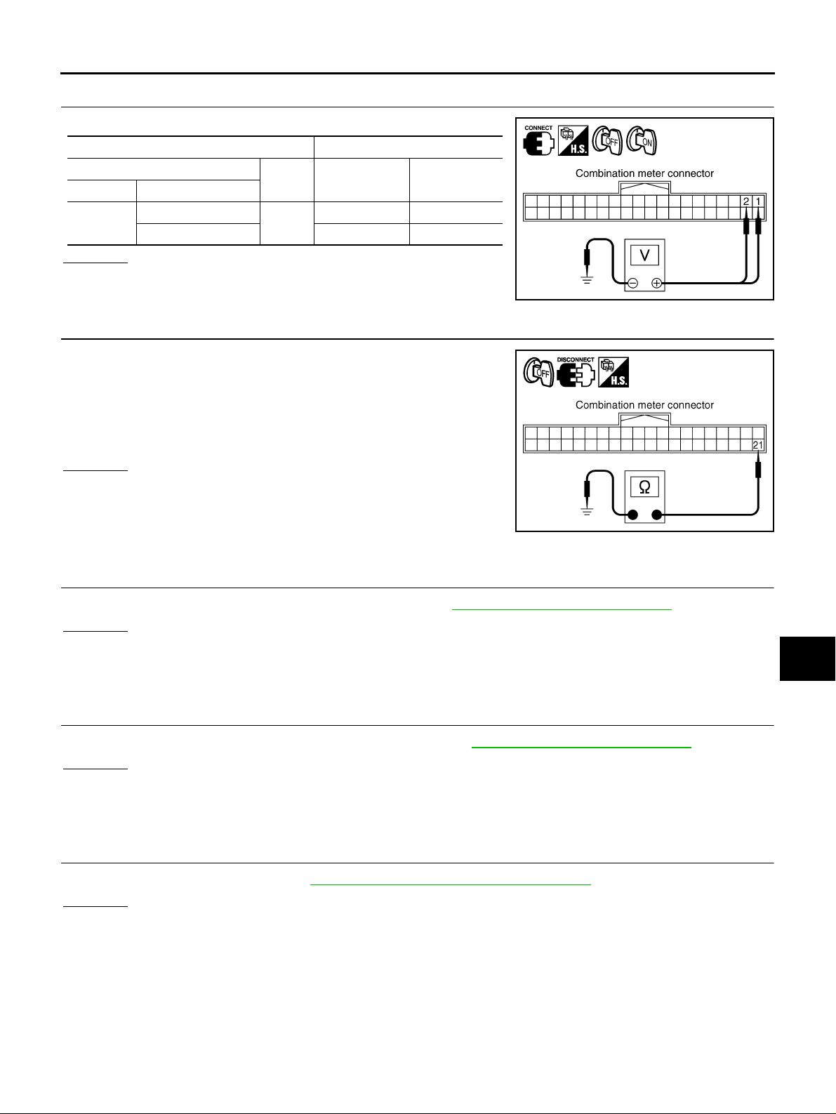
2. CHECK POWER SUPPLY CIRCUIT
Check voltage between combination meter and ground.
Terminals Ignition switch position
(+)
Connector Terminal (Wire color)
M44
OK or NG
OK >> GO TO 3.
NG >> Check harness between combination meter and fuse.
2 (Y/G)
1 (L) Battery voltage Battery voltage
(–) OFF ON
Ground
0 V Battery voltage
3. CHECK GROUND CIRCUIT
1. Turn ignition switch OFF.
2. Disconnect combination meter conn ector.
3. Check continuity between combination meter harness connector
M44 terminal 21 (B) and ground.
21 (B) – Ground : Continuity should exist.
OK or NG
OK >> Power supply and ground circuit is OK.
NG >> Repair ground harness.
A
B
C
D
SKIB0600E
E
F
G
H
SKIB0601E
Vehicle Speed Signal Inspection (With VDC) AKS00BLQ
1. CHECK VDC/TCS/ABS CONTROL UNIT SELF-DIAGNOSIS
Preform VDC/TCS/ABS control unit self-diagnosis. Refer to BRC-61, "
OK or NG
OK >> Replace combination meter.
NG >> Check applicable p arts, repa ir or replace corresponding parts.
Vehicle Speed Signal Inspection (Without VDC) AKS00BAG
CONSULT-II Functions" .
1. CHECK ABS ACTUATOR AND ELECTRIC UNIT SELF-DIAGNOSIS
Preform ABS actuator and electric unit self-diagnosis. Refer to BRC-19, "
OK or NG
OK >> Replace combination meter.
NG >> Check applicable p arts, repa ir or replace corresponding parts.
Engine Speed Signal Inspection AKS00BAE
CONSULT-II Functions" .
1. CHECK ECM SELF-DIAGNOSIS
Perform ECM self-diagn os is . Refe r to EC-123, "
OK or NG
OK >> Replace combination meter.
NG >> Perform “Diagnostic Procedure” in displayed DTC.
CONSULT-II Function (ENGINE)" .
I
J
DI
L
M
Revision: 2005 March 2005 X-Trail
DI-17
Page 18
COMBINATION METERS
Engine Coolant Temperature Signal Inspection AKS00BAF
1. CHECK ECM SELF-DIAGNOSIS
Perform ECM self-diagnosis . Refer to EC-123, "
OK or NG
OK >> Replace combination meter.
NG >> Perform “Diagnosti c Procedure” in displayed DTC .
CONSULT-II Function (ENGINE)" .
Fuel Level Sensor Inspection AKS00BAC
NOTE:
The following symptoms are not malfunction.
FUEL GAUGE
● Depending on vehicle posture or driving c ircumstances, fuel level in tank varies , and the pointer may fluc-
tuate.
● If the vehicle is fueled with ignition switch ON, the pointer moves slowly.
LOW-FUEL WARNING LAMP
● Depending on vehi cle posture or driving c ircumstances, fuel level in tank varies, and warni ng lamp ON
timing may change .
1. CHECK HARNESS CONNECTOR
Check combinati on meter and fuel lev el sensor unit termi nals (meter side, unit s ide, harness side ) for looseness or bent terminals .
OK or NG
OK >> GO TO 2.
NG >> Repair terminal or connector.
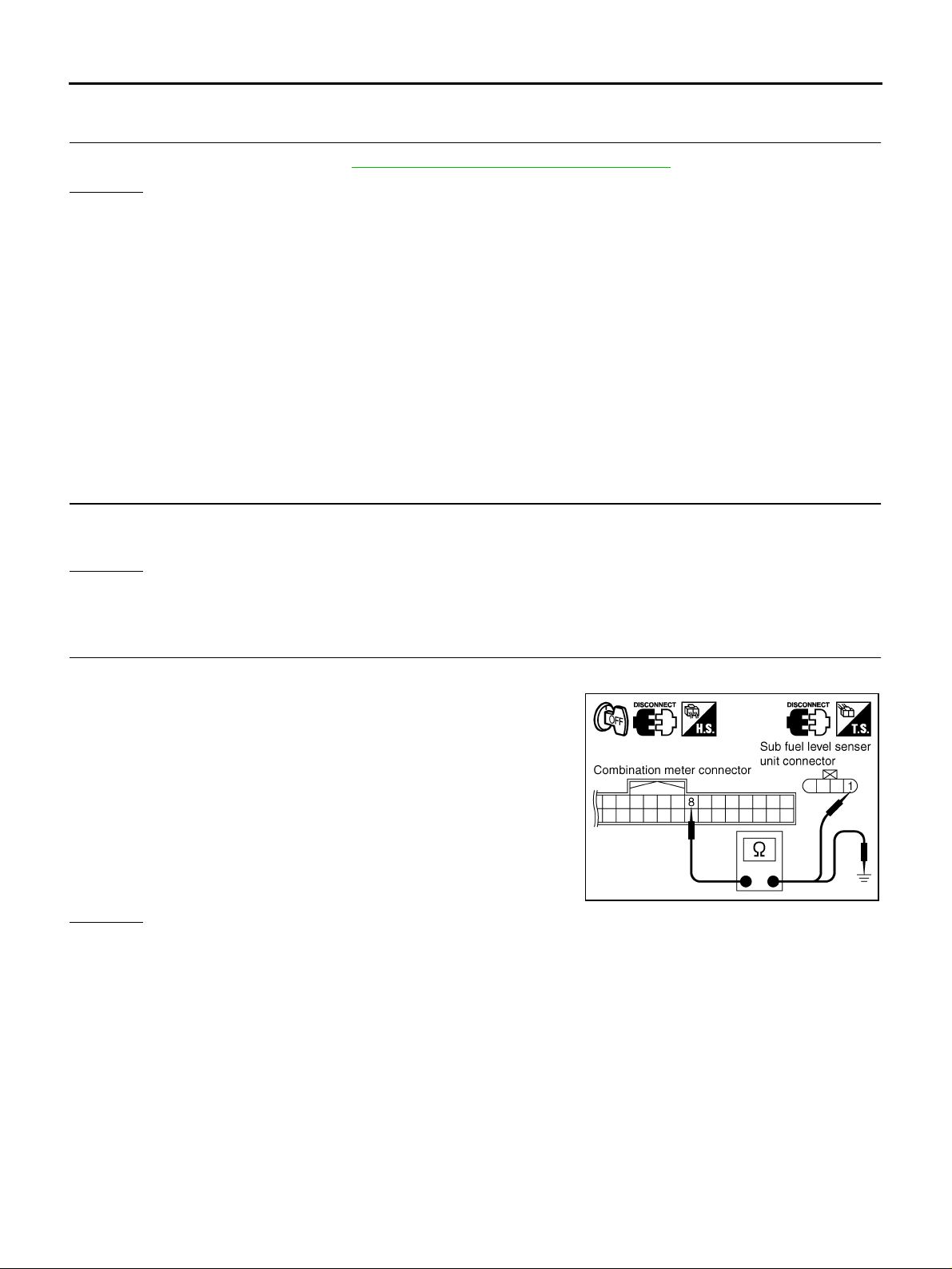
2. CHECK COMBINATION METER CIRCUIT
1. Turn ignition switch OFF.
2. Disconnect com bi na tio n me t er co nn ec tor an d su b fue l l ev el sen sor unit conn ector.
3. Check continu i ty be tw ee n c omb inat i on me ter h arn ess co nn ec tor
M44 terminal 8 (G) and sub fuel level sensor unit harness connector B125 terminal 1 (G).
8 (G) – 1 (G) : Continuity should exist.
4. Check continu i ty be tw ee n c omb inat i on me ter h arn ess co nn ec tor
M44 terminal 8 (G) and ground.
8 (G) – Ground : Continuity should not exist.
OK or NG
OK >> GO TO 3.
NG >> Repair harness or connector.
SKIA8924E
Revision: 2005 March 2005 X-Trail
DI-18
Page 19
COMBINATION METERS
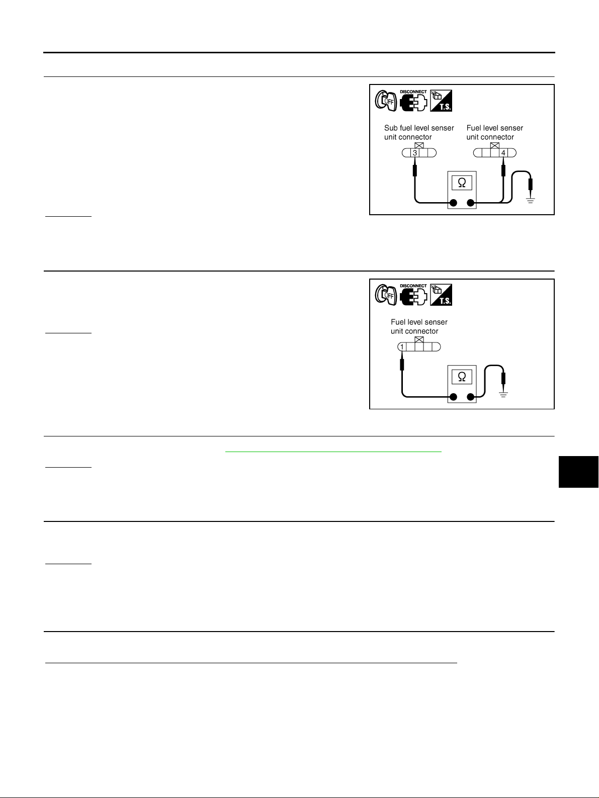
3. CHECK FUEL LEVEL SENSOR CIRCUIT
1. Disco nn ec t fuel lev el se ns or un it co nn ec tor.
2. Check continuity between sub fuel level sensor unit harness
connector B1 25 t erm in al 3 ( Y) a nd fu el l ev el se ns or u ni t har n es s
connector B31 terminal 4 (Y).
3 (Y) – 4 (Y) : Continuity should exist.
3. Check continuity between sub fuel level sensor unit harness
connector B125 terminal 3 (Y) and ground.
3 (Y) – Ground : Continuity should not exist.
OK or NG
OK >> GO TO 4.
NG >> Repair harness or connector.
4. CHECK GROUND CIRCUIT
Check continu ity between fuel level se nsor unit harness connecto r
B31 terminal 1 (B) and ground.
1 (B) – Ground : Continuity should exist.
OK or NG
OK >> GO TO 5.
NG >> Repair harness or connector.
A
B
C
D
SKIA8925E
E
F
G
H
SKIA8926E
5. CHECK FUEL LEVEL SENSOR
Check fuel level sensor units. Refer to DI-23, "
OK or NG
OK >> GO TO 6.
NG >> Replace fuel level sensor unit or sub fuel level sensor unit.
FUEL LEVEL SENSOR UNIT CHECK" .
6. CHECK INSTALLATION CONDITION
Check fuel level sensor unit installation, and check whether the float arm interferes or binds with any of the
internal components in fuel tank.
OK or NG
OK >> Replace combination meter.
NG >> Install fuel level sensor unit properly.
The Fuel Gauge Pointer Fluctuates, Indicator Wrong Value or Varies AKS00BAH
1. CHECK FUEL GAUGE FLUCTUATION
Test drive vehicle to see if gauge fluctuates only during driving and just before or soon after stopping.
Does the indication value vary only during driving and just bef ore or soon after stopping?
YES >> The pointer fluctuation may be caused by fuel level change in fuel tank. Condition is normal.
NO >> Ask the customer about the situation when the symptom occurs in detail, and perform the trouble
diagnosis.
I
J
DI
L
M
Revision: 2005 March 2005 X-Trail
DI-19
Page 20
COMBINATION METERS
The Fuel Gauge Does Not Move to FULL Position AKS00BAI
1. QUESTION 1
Does it take a long time for the pointer to move to FULL position?
YES or NO
YES >> GO TO 2.
NO >> GO TO 3.
2. QUESTION 2
Was the vehicle fueled with ignition switch ON?
YES or NO
YES >> Be sure to fu el the vehicl e with ig nition switch OF F. Otherwise, it will take a long time to move to
FULL position because of the characteristic of fuel gauge.
NO >> GO TO 3.
3. QUESTION 3
Is the vehicle parked on an incline?
YES or NO
YES >> Check the fuel level indica tion with vehicle on a level surface.
NO >> GO TO 4.
4. QUESTION 4
During driving, does fuel gauge pointer move gradually toward EMPTY position?
YES or NO
YES >> Check fuel level sensor unit. Refer to DI-23, "FUEL LEVEL SENSOR UNIT CHECK" .
NO >> The float arm may interfere or bind with any of the components in fuel tank.
Ambient Temperature Signal Inspection [Without Auto A/C] AKS00BAJ
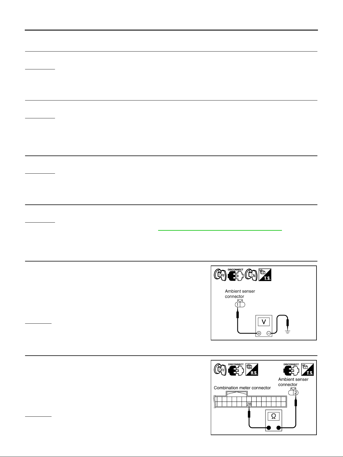
1. CHECK VOLTAGE BETWEEN AMBIENT SENSOR HARNESS CONNECTOR AND GROUND
1. Turn ignition switch OFF.
2. Disconnect ambient sensor connector.
3. Turn ignition switch ON.
4. Check voltage be tween ambien t sensor harne ss connector E38
terminal 1 (R /B) and ground.
1 (R/B) – Ground : Approx. 5 V
OK or NG
OK >> GO TO 2.
NG >> GO TO 4.
SKIB0602E
2. CHECK AMBIENT SENSOR CIRCUIT BETWEEN AMBIENT SENSOR AND COMBINATION METER
1. Turn ignition switch OFF.
2. Disconnect combination meter connector.
3. Check continu i ty be tw ee n c omb inat i on me ter h arn ess co nn ec tor
M44 terminal 28 (B/Y) and ambient sensor harness connector
E38 terminal 2 (B/Y).
28 (B/Y) – 2 (B/Y) : Continuity should exist.
OK or NG
OK >> GO TO 3.
NG >> Repair harness or connector.
Revision: 2005 March 2005 X-Trail
DI-20
SKIA9134E
Page 21
COMBINATION METERS
3. CHECK AMBIENT SENSOR
Check ambient senso r. Refer to DI-23, "
OK or NG
OK >> Replace combination meter.
NG >> Replace ambient sensor.
AMBIENT SENSOR CHECK" .
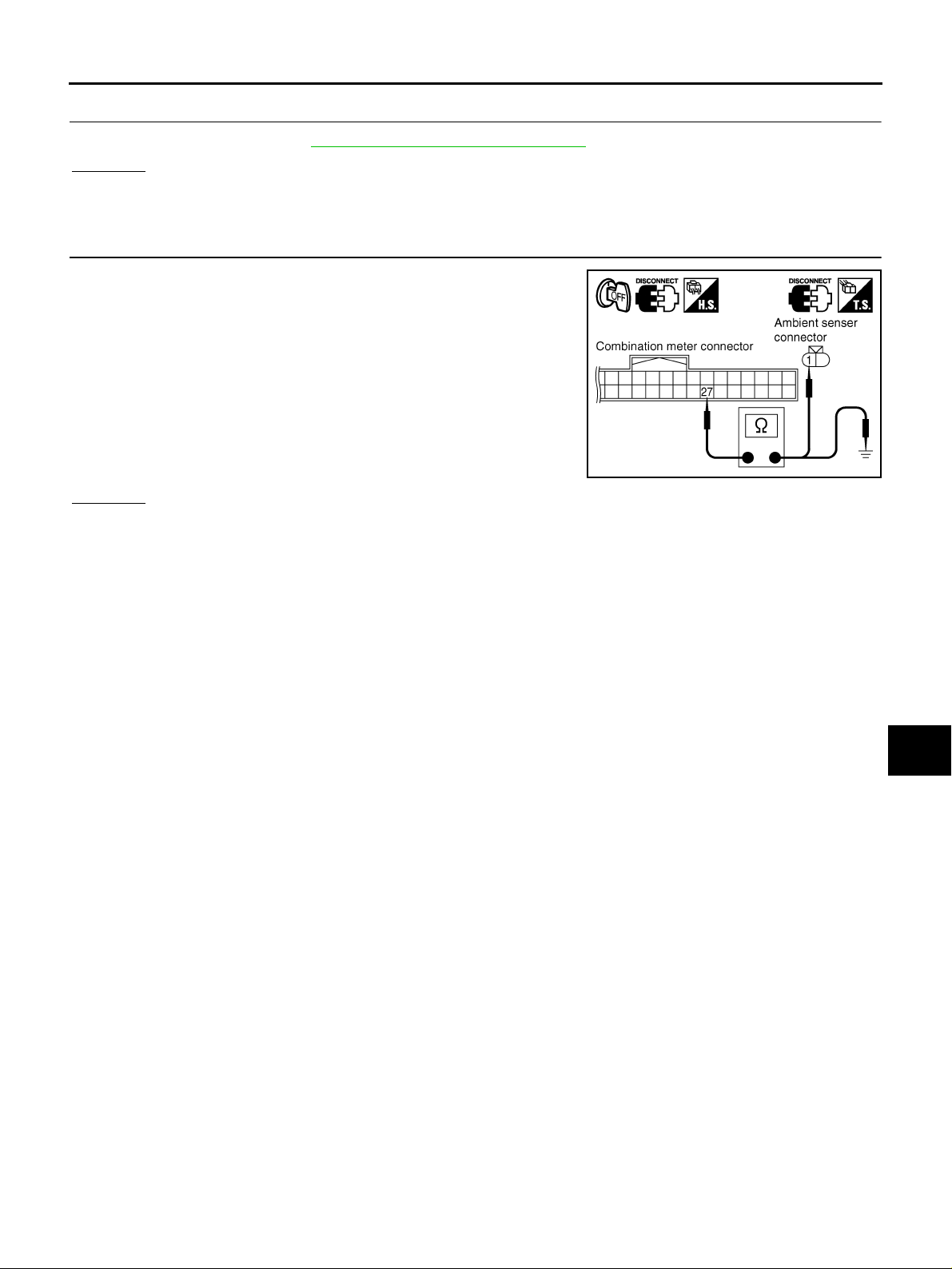
4. CHECK AMBIENT SENSOR CIRCUIT BETWEEN AMBIENT SENSOR AND COMBINATION METER
1. Turn ignition switch OFF.
2. Disconnect combination meter conn ector.
3. Check continuity between combination meter harness connector
M44 terminal 27 (R /B) and am bi en t sen sor co nn ec t or E3 8 t er m inal 1 (R/B).
27 (R/B) – 1 (R/B) : Continuity should exist.
4. Check continuity between combination meter harness connector
M44 terminal 27 (R/B) and ground.
27 (R/B) – Ground : Continuity should not exist.
OK or NG
OK >> Replace combination meter.
NG >> Repair harness or connector.
SKIA9135E
A
B
C
D
E
F
G
H
DI
I
J
L
M
Revision: 2005 March 2005 X-Trail
DI-21
Page 22
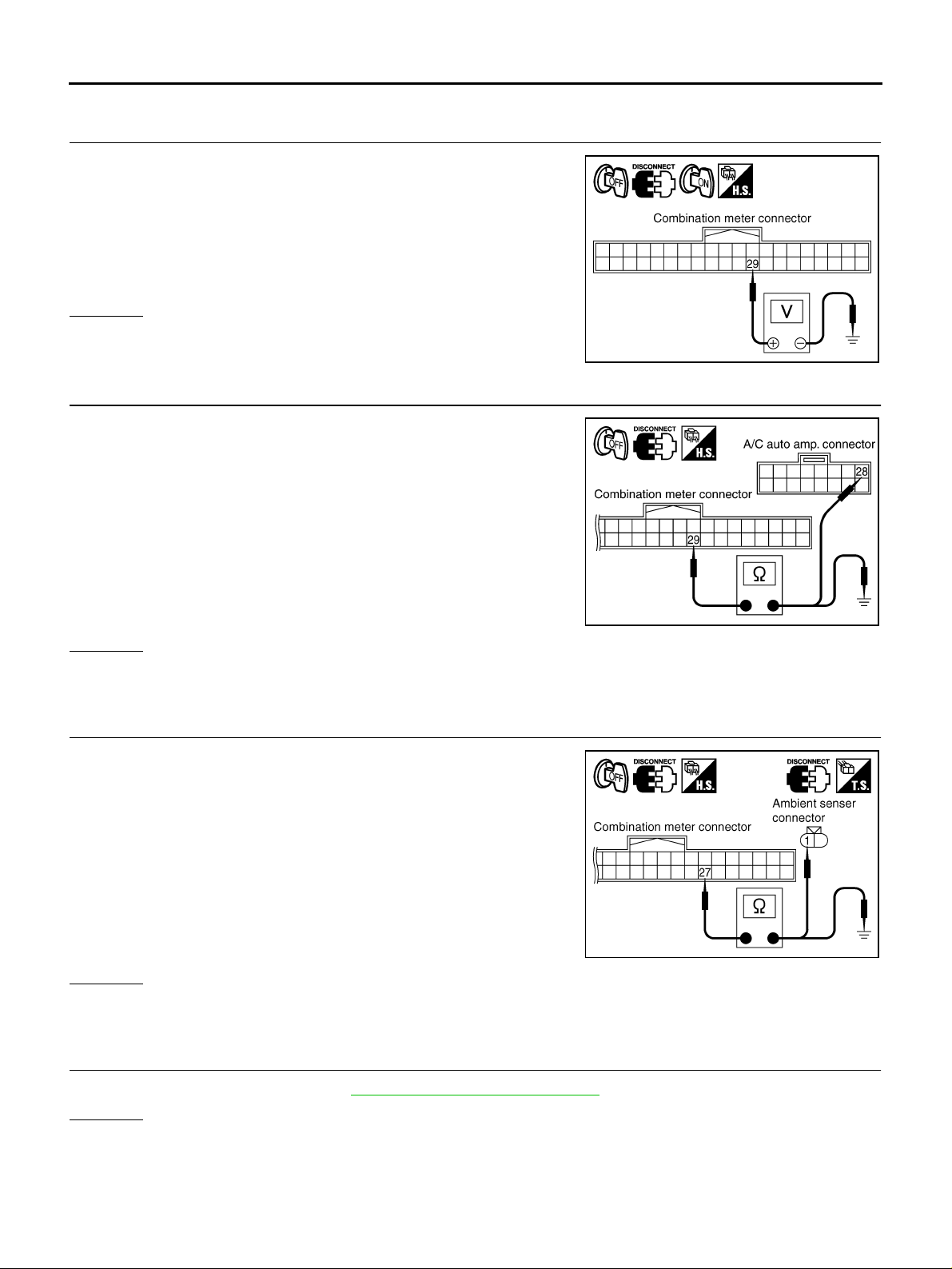
COMBINATION METERS
Ambient Temperature Signal Inspection [With Auto A/C] AKS00BAK
1. CHECK AUTO A/C RECOGNITION SIGNAL INPUT
1. Turn ignition switch OFF.
2. Disconnect combination meter connector.
3. Turn ignition switch ON.
4. Check voltage between combination meter harness connector
M44 terminal 29 (Y) and ground.
29 (Y) – Ground : Approx. 5 V
OK or NG
OK >> GO TO 3.
NG >> GO TO 2.
SKIB0603E
2. CHECK AUTO A/C RECOGNITION SIGNAL CIRCUIT
1. Turn ignition switch OFF.
2. Disconnect A/C auto amp. connector.
3. Check continu i ty be tw ee n c omb inat i on me ter h arn ess co nnec to r
M44 terminal 29 (Y) and A/C a uto amp. harnes s co nnec tor M53
terminal 28(Y).
29 (Y) – 28 (Y) : Continuity should exist.
4. Check continuity between connector M44 terminal 29 (Y) and
ground.
29 (Y) – Ground : Continuity should not exist.
OK or NG
OK >> Replace A/C auto amp.
NG >> Repair harness or connector.
SKIB0604E
3. CHECK AMBIENT SENSOR CIRCUIT BETWEEN AMBIENT SENSOR AND COMBINATION METER
1. Turn ignition switch OFF.
2. Disconnect ambient sensor connector.
3. Check continu i ty be tw ee n c omb inat i on me ter h arn ess co nn ec tor
M44 terminal 27 (R/B) and ambient sensor harness connector
E38 terminal 1 (R/B).
27 (R/B) – 1 (R/B) : Continuity should exist.
4. Check continu i ty be tw ee n c omb inat i on me ter h arn ess co nn ec tor
M44 terminal 27 (R/B) and ground.
27 (R/B) – Ground : Continuity should not exist.
OK or NG
OK >> GO TO 4.
NG >> Repair harness or connector.
SKIA9135E
4. CHECK A/C AUTO AMP. CIRCUIT
Check A/C auto amp. circu it. Ref er to ATC-89, "
OK or NG
OK >> Replace combination meter.
NG >> Check applicable parts, repair or replace corresponding parts.
Revision: 2005 March 2005 X-Trail
Ambient Sensor Circuit" in ATC section.
DI-22
Page 23
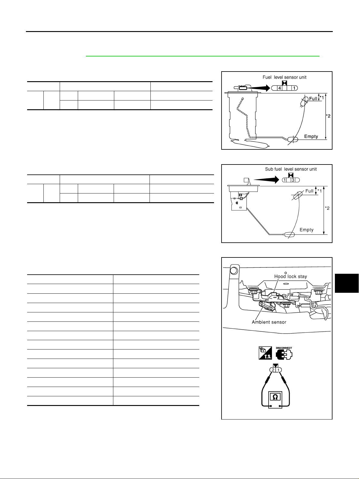
COMBINATION METERS
Electrical Components Inspection AKS00BAL
FUEL LEVEL SENSOR UNIT CHECK
For removal, refer to FL-4, "FUEL LEVEL SENSOR UNIT, FUEL FILTER AND FUEL PUMP ASSEMBLY" .
A
Fuel Level Sensor Unit
Check the resistance be tw ee n term in al s 1 and 4.
Terminals Float position mm (in) Resistance value Ω
41
*1 and *2: When float rod is in contact with stopper.
*1 Full 30 (1.18) Approx. 5
*2 Empty 159 (6.25) Approx. 80
Sub Fuel Level Sensor Unit
Check the resistance be tw ee n term in al s 1 and 3.
Terminals Float position mm (in) Resistance value Ω
13
*1 and *2: When float rod is in contact with stopper.
*1 Full 30 (1.18) Approx. 1
*2 Empty 191 (7.52) Approx. 40.5
SKIB0605E
SKIB0606E
B
C
D
E
F
G
H
I
AMBIENT SENSOR CHECK
After disconnec ting ambient sensor connector, measure resistance
between terminals 2 and 1 at sensor side, using the table below.
Temperature °C (°F) Resistance kΩ
-15 (5) 12.73
-10 (14) 9.92
-5 (23) 7.80
0 (32) 6.19
5 (41) 4.95
10 (50) 3.99
15 (59) 3.24
20 (68) 2.65
25 (77) 2.19
30 (86) 1.81
35 (95) 1.51
40 (104) 1.27
45 (113) 1.07
If NG, replace ambient senso r.
J
DI
L
M
RJIA0684E
Revision: 2005 March 2005 X-Trail
DI-23
Page 24
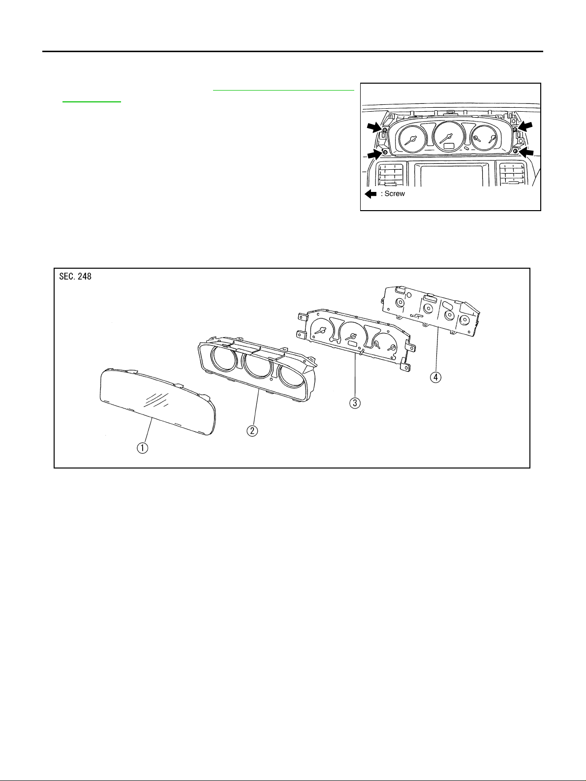
COMBINATION METERS
Removal and Installation for Combination Meter AKS00BAM
REMOVAL
1. Remove cluster lid A. Refer to IP-10, "INSTRUMENT PANEL
ASSEMBLY" .
2. Remove the scre ws (4), and pull out combination meter.
3. Disconnect connectors and r emove combination meter.
SKIA8927E
INSTALLATION
Installat ion is the rever se order of removal.
Disassembly and Assembly for Combination Meter AKS00BAN
1. Front cover 2. Upper housing 3. Unified meter control unit assembly
4. Meter cover
DISASSEMBLY
1. Disengaged the tabs (8) to separate front cover.
2. Disengaged the tabs (8) to separate upper housing.
3. Disengaged the tabs (8) to separate meter cover.
ASSEMBLY
Assembly is the reverse order of disassembly.
SKIA7344J
Revision: 2005 March 2005 X-Trail
DI-24
Page 25
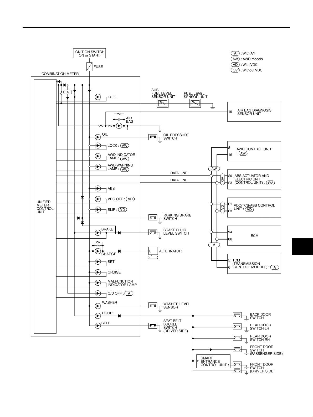
WARNING LAMPS
WARNING LAMPS PFP:24814
Schematic AKS00BAO
A
B
C
D
E
F
G
DI
H
I
J
L
M
TKWB0175E
Revision: 2005 March 2005 X-Trail
DI-25
Page 26
WARNING LAMPS
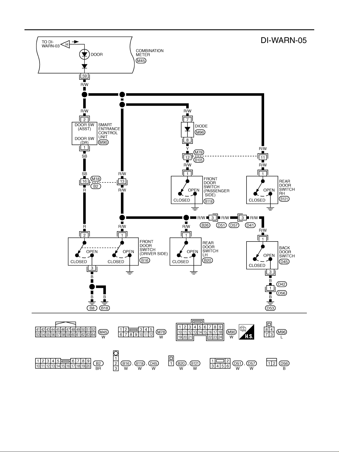
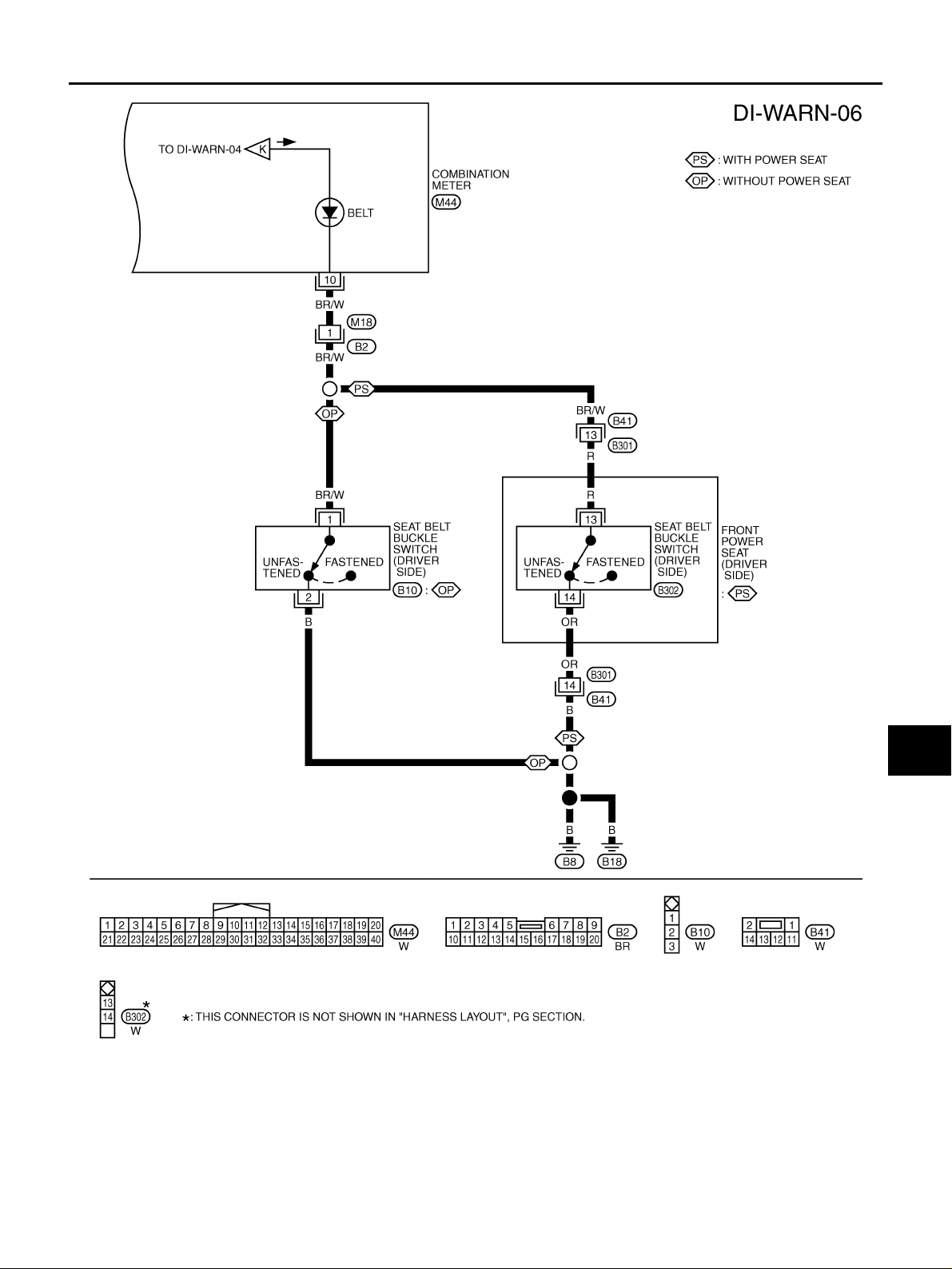
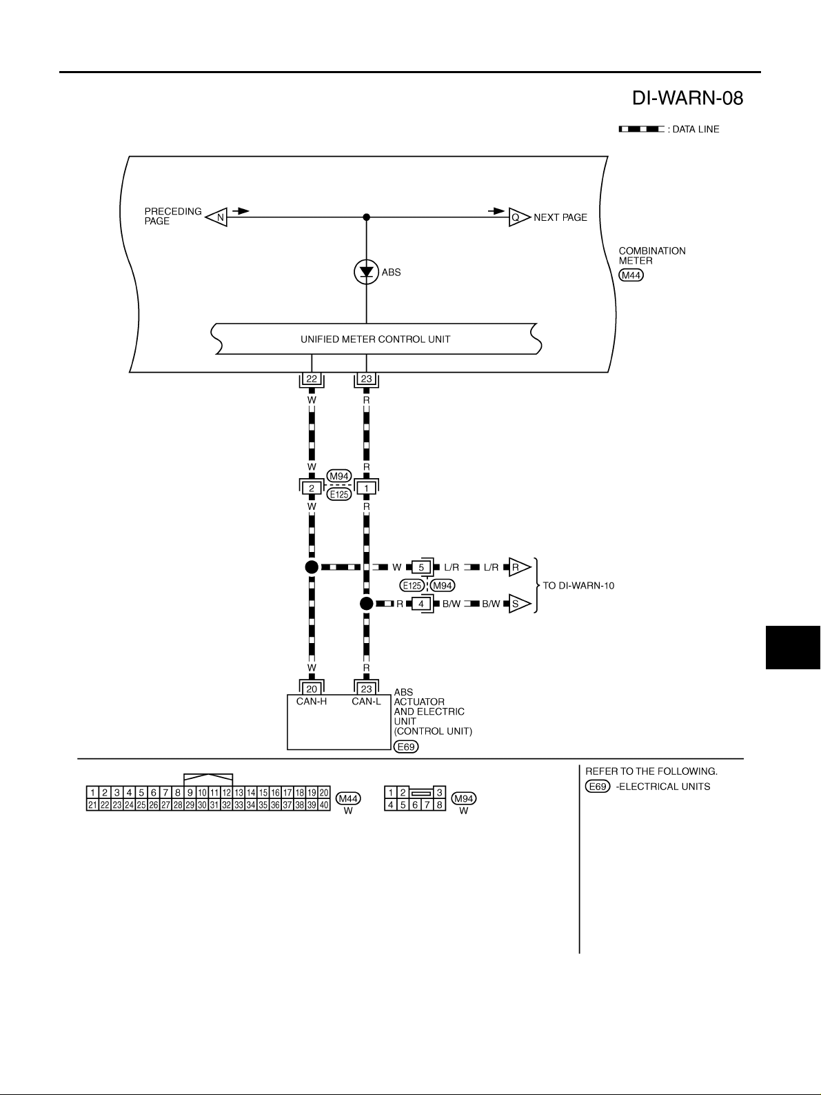
Wiring Diagram — WARN — AKS00BAP
AWD MODELS
TKWB0176E
Revision: 2005 March 2005 X-Trail
DI-26
Page 27
WARNING LAMPS
A
B
C
D
E
F
G
DI
H
I
J
L
M
TKWB0177E
Revision: 2005 March 2005 X-Trail
DI-27
Page 28
WARNING LAMPS
TKWB0178E
Revision: 2005 March 2005 X-Trail
DI-28
Page 29
WARNING LAMPS
A
B
C
D
E
F
G
DI
H
I
J
L
M
TKWB0179E
Revision: 2005 March 2005 X-Trail
DI-29
Page 30
WARNING LAMPS
TKWB0180E
Revision: 2005 March 2005 X-Trail
DI-30
Page 31
WARNING LAMPS
A
B
C
D
E
F
G
DI
H
I
J
L
M
TKWB0181E
Revision: 2005 March 2005 X-Trail
DI-31
Page 32
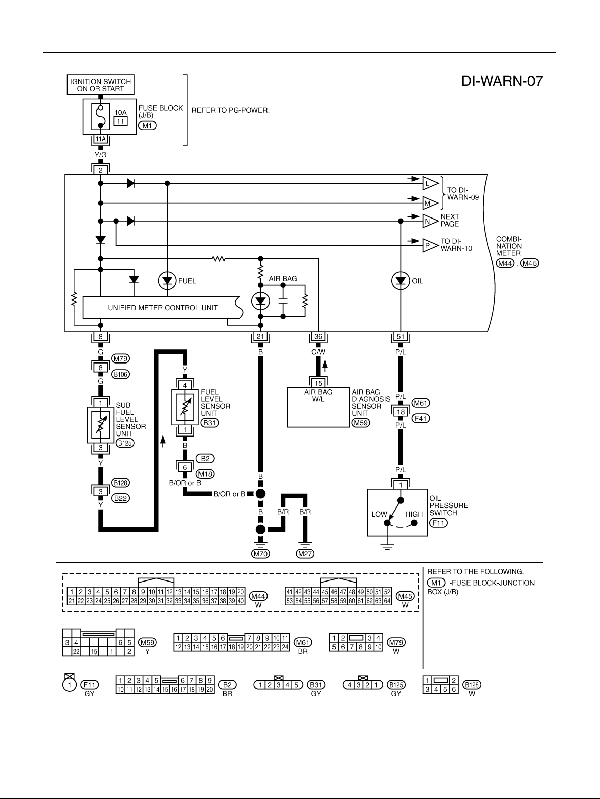
2WD MODELS
WARNING LAMPS
TKWB0182E
Revision: 2005 March 2005 X-Trail
DI-32
Page 33
WARNING LAMPS
A
B
C
D
E
F
G
DI
H
I
J
L
M
TKWB0183E
Revision: 2005 March 2005 X-Trail
DI-33
Page 34
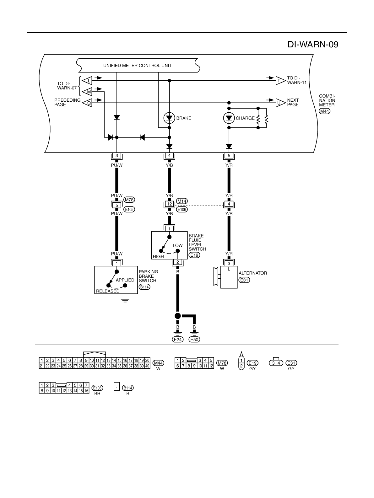
WARNING LAMPS
TKWB0184E
Revision: 2005 March 2005 X-Trail
DI-34
Page 35
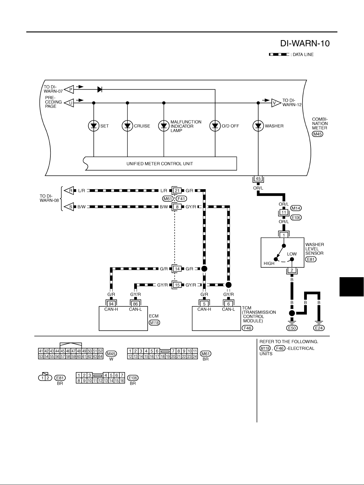
WARNING LAMPS
A
B
C
D
E
F
G
DI
H
I
J
L
M
TKWB0185E
Revision: 2005 March 2005 X-Trail
DI-35
Page 36
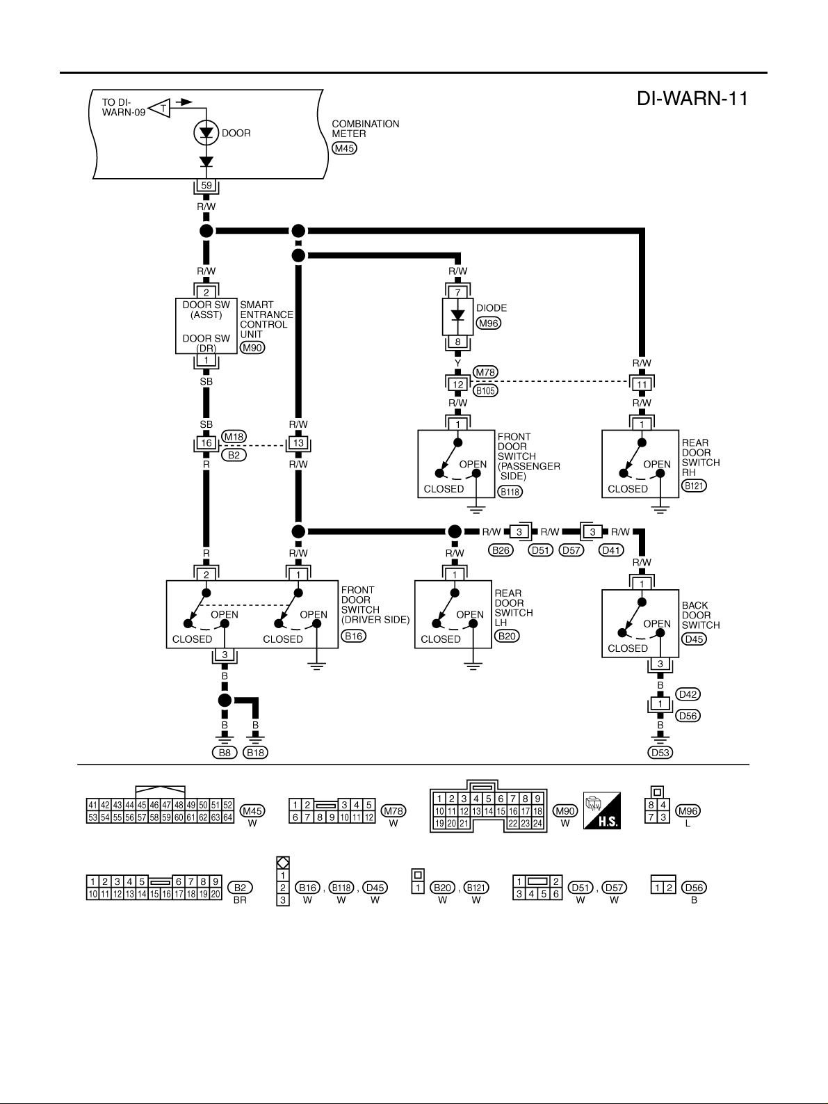
WARNING LAMPS
TKWB0186E
Revision: 2005 March 2005 X-Trail
DI-36
Page 37
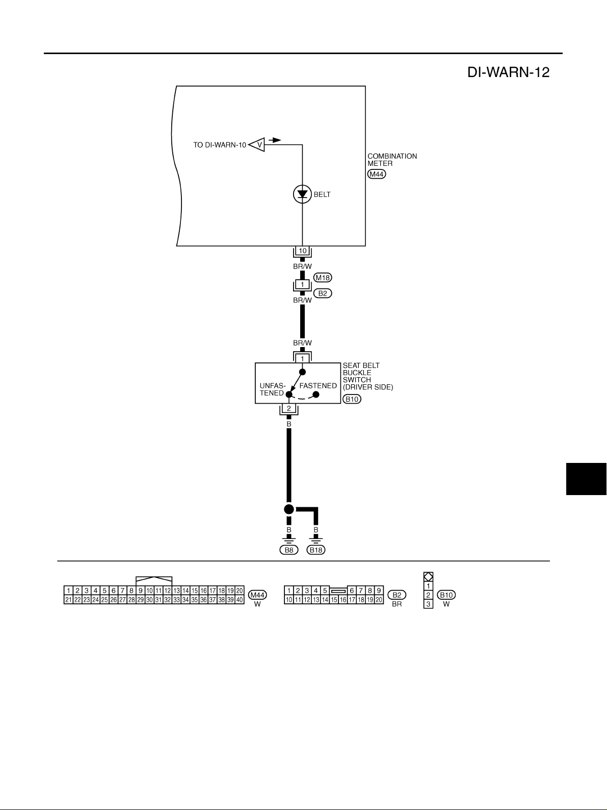
WARNING LAMPS
A
B
C
D
E
F
G
DI
H
I
J
L
M
TKWB0187E
Revision: 2005 March 2005 X-Trail
DI-37
Page 38
WARNING LAMPS
Electrical Components Inspection AKS00BAT
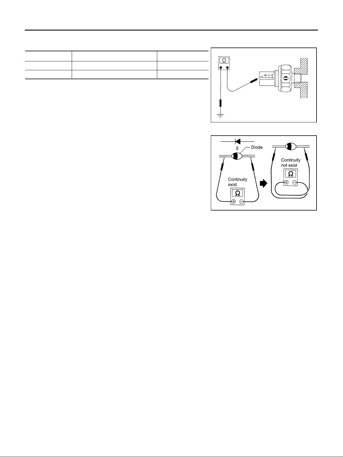
OIL PRESSURE SWITCH CHECK
Condition
Engine running More than 29 (0.3, 4) No
Engine stopped Less than 29 (0 .3, 4) Yes
Oil pressure kPa (kg/cm
2
, psi)
Continuity
Check the continuity between the terminals of oil pressure switch
and body ground.
DIODE CHECK
● Check continuity using an ohmmeter.
● Diode is functioning properly if test results are as shown in the
figure at left.
● Check diodes at the combination meter harness connector
instead of on the combination meter assembly.
NOTE:
Specification may vary depending on the type of tester. Before
performing this inspection, be sure to refer to the instruction
manual for the tester to be used.
ELF0044D
SKIB0607E
Revision: 2005 March 2005 X-Trail
DI-38
Page 39
A/T INDICATOR
A/T INDICATOR PFP:24814
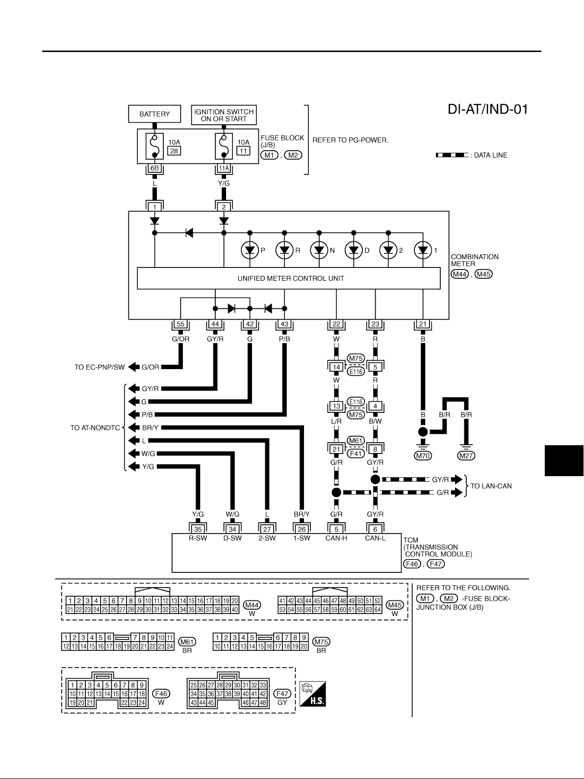
Wiring Diagram — AT/IND — AKS00BAV
AWD MODE LS
A
B
C
D
E
F
G
DI
H
I
J
L
M
TKWA1850E
Revision: 2005 March 2005 X-Trail
DI-39
Page 40
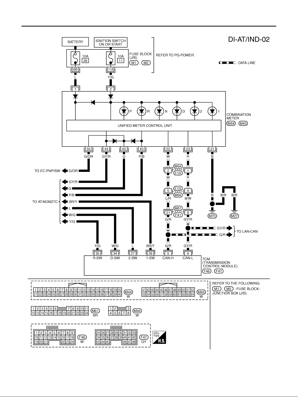
2WD MODELS
A/T INDICATOR
TKWA1851E
Revision: 2005 March 2005 X-Trail
DI-40
Page 41

A/T INDICATOR
A/T Indicator Does Not Illuminate AKS00BAX
1. CHECK TCM SELF-DIAGNOSIS
A
Perform TCM self-diagn os is . Refe r to AT-80, "
OK or NG
OK >> Replace combination meter.
NG >> Go to TCM trouble diagnosis.
CONSULT-II Function (A/T)" .
B
C
D
E
F
G
H
DI
I
J
L
M
Revision: 2005 March 2005 X-Trail
DI-41
Page 42

WARNING CHIME
WARNING CHIME PFP:28596 System Description AKS00BB4
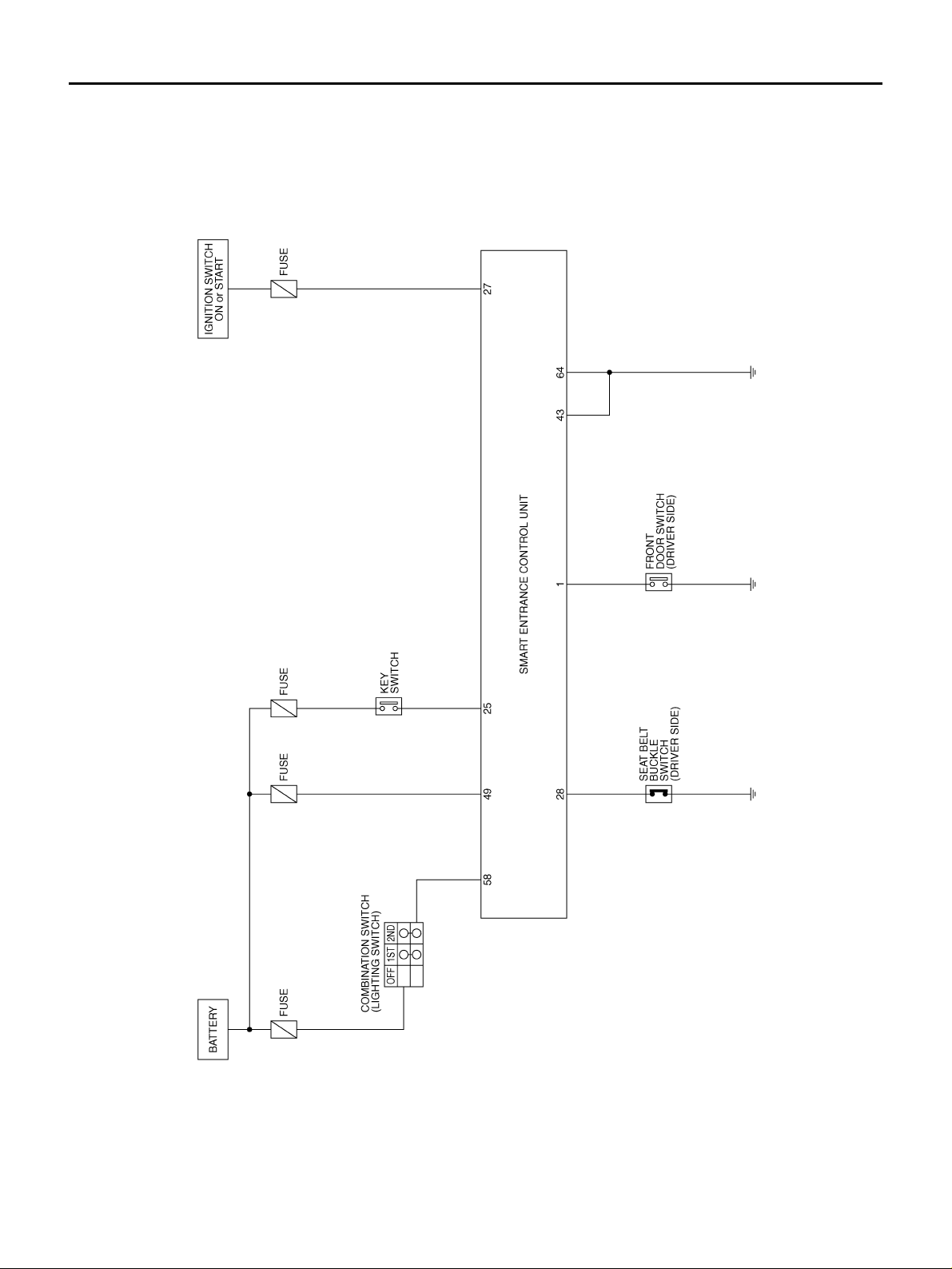
The warning chime is controlled by the smart entrance control unit.
When a signal, or com bina tio n of sign als, is recei ved by the sma rt ent ran ce contr ol un it, th e warni ng chime will
sound.
The warning c hime is located in the smart en trance control unit.
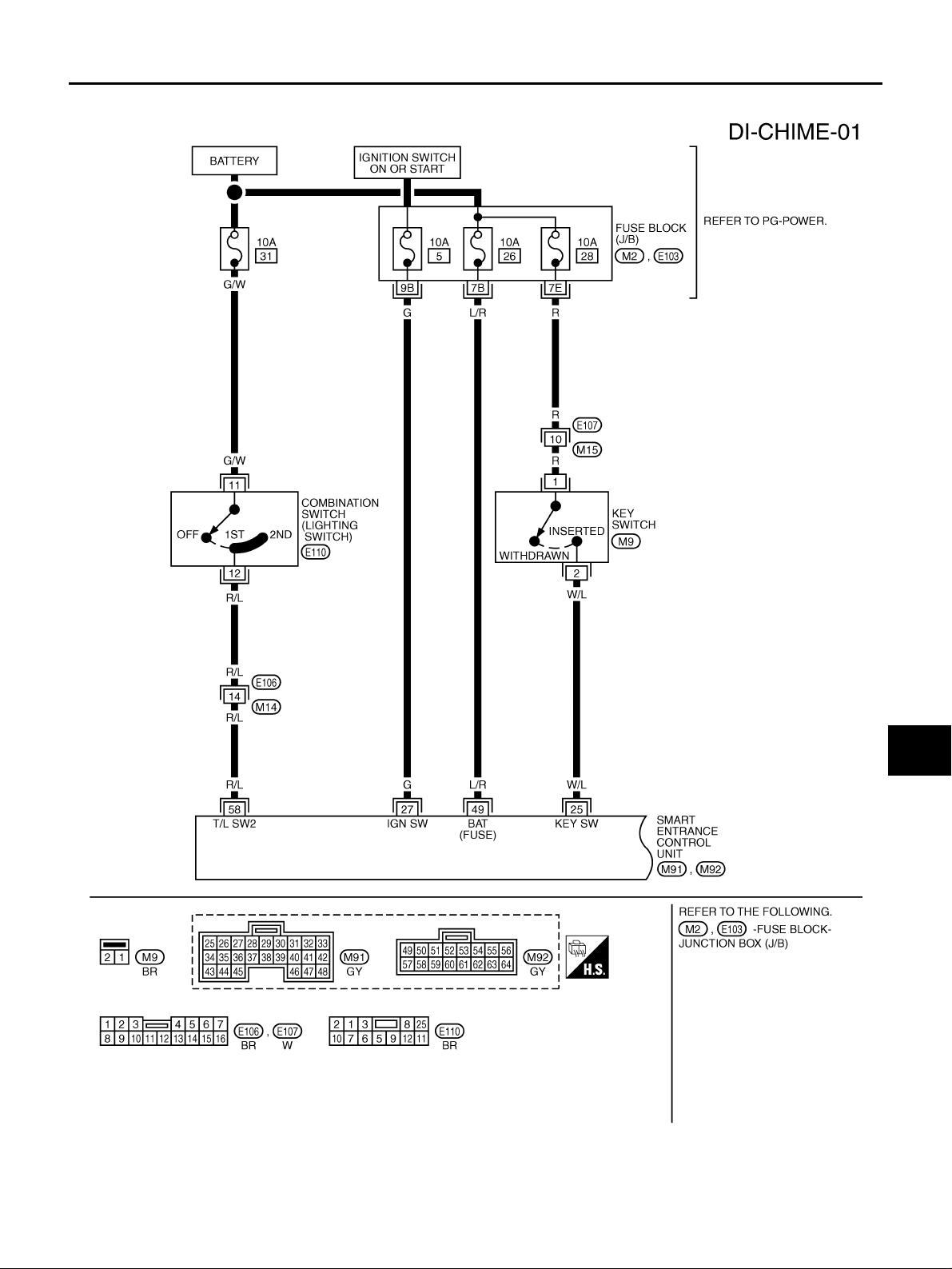
POWER SUPPLY AND GROUND CIRCUIT
Power is supplied at all time s
● through 10 A fuse [No. 26, located in the fuse block (J/B)]
● to smart entrance control unit terminal 49
● through 10 A fuse [No. 28, located in the fuse block (J/B)]
● to key switch terminal 1
● through 10 A fuse (No. 31, located in fuse and fusible link box)
● to combination switch terminal 11.
With ignition switch in ON or START position, power is supplied
● through 10 A fuse [No. 5, located in the fuse block (J/B)]
● to smart entrance control unit terminal 27.
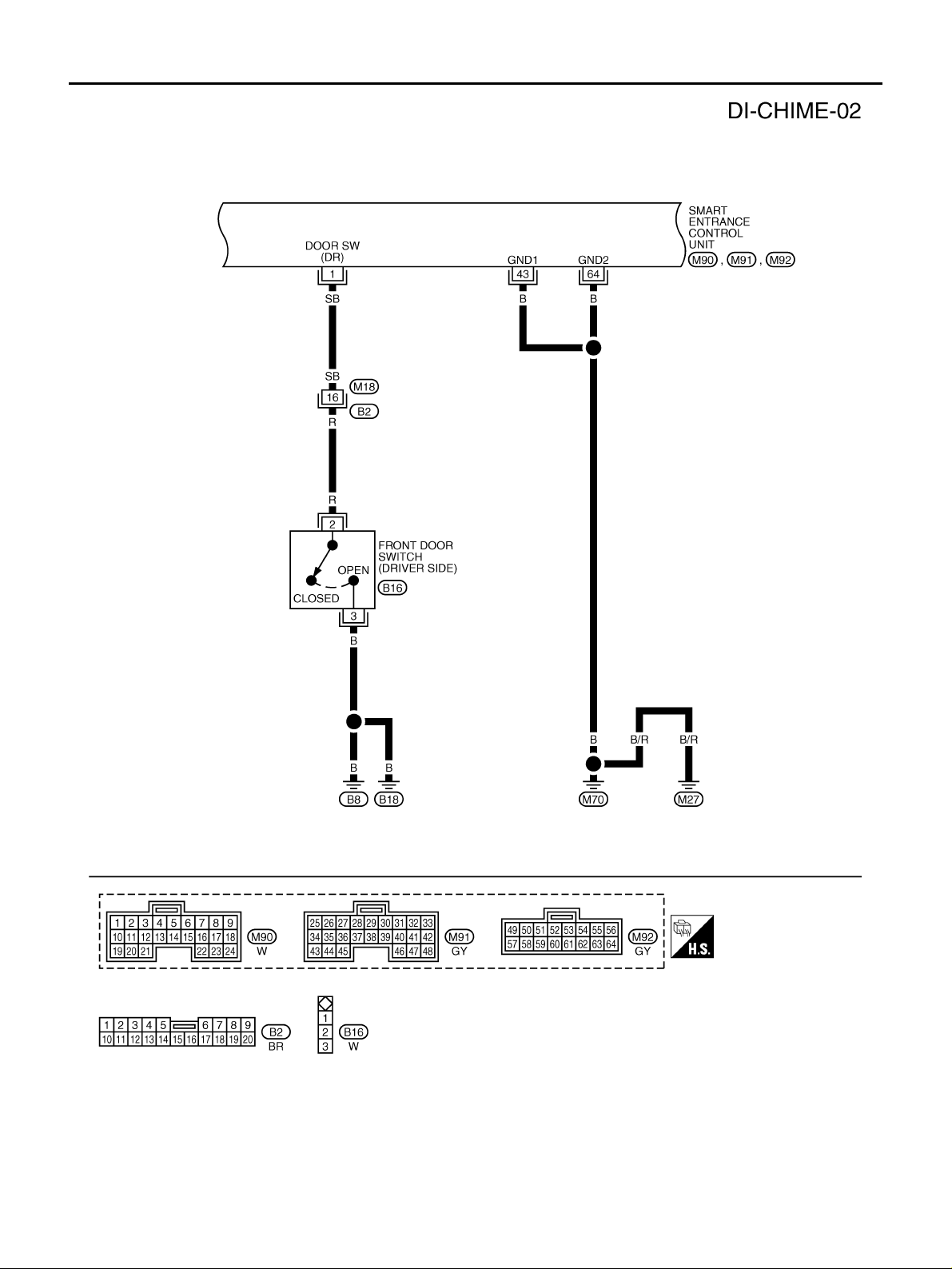
Ground is supplied
● to smart entrance control unit terminals 43 and 64
● through grounds M27 and M70.
IGNITION KEY WARNING CHIME
With key is insert ed in the ignition key cylin der (OFF or ACC positi on), and th e driver d oor open , the wa rning
chime will sound.
Power is supplied as a signal
● through key switch terminal 2
● to smart entrance control unit terminal 25
Ground is supplied as a signal
● from front door switch (driver side) terminal 2
● to smart entrance control unit terminal 1.
Front door switch (driver side) terminal 3 is grounded through grounds B8 and B18.
LIGHT WARNING CHIME
With ignition swi tch in OFF or A CC po sitio n, dri ver do or open and light ing switc h in 1st o r 2nd p osit io n, warn ing chime will sound.
Power is supplied as a signal
● through lighting switch terminal 12
● to smart entrance control unit terminal 58.
Ground is supplied as a signal
● from front door switch (driver side) terminal 2
● to smart entrance control unit terminal 1.
Front door switch (driver side) terminal 3 is grounded through grounds B8 and B18.
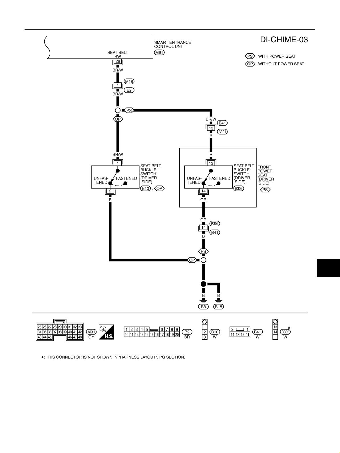
SEAT BELT WARNING CHIME
With ignition s witch turned ON and seat belt unf astened [seat belt b uckle switch (driver side) ON], warning
chime will sound for ap pro ximately 6 seconds.
Without Power Seat
Ground is supplied as a signal
● from seat belt buckle switch (driver side) terminal 1
● to smart entrance control unit terminal 28.
Seat belt buckle switch (dri ver side) terminal 2 is grounded through grounds B8 and B18.
Revision: 2005 March 2005 X-Trail
DI-42
Page 43
WARNING CHIME
With Power Seat
Ground is supplie d as a sign al
● from seat belt buckle switch ( driver side) terminal 13
● to smart entrance control unit terminal 28.
Seat belt buckle switch (driver side) terminal 14 is grounded through grounds B8 and B18.
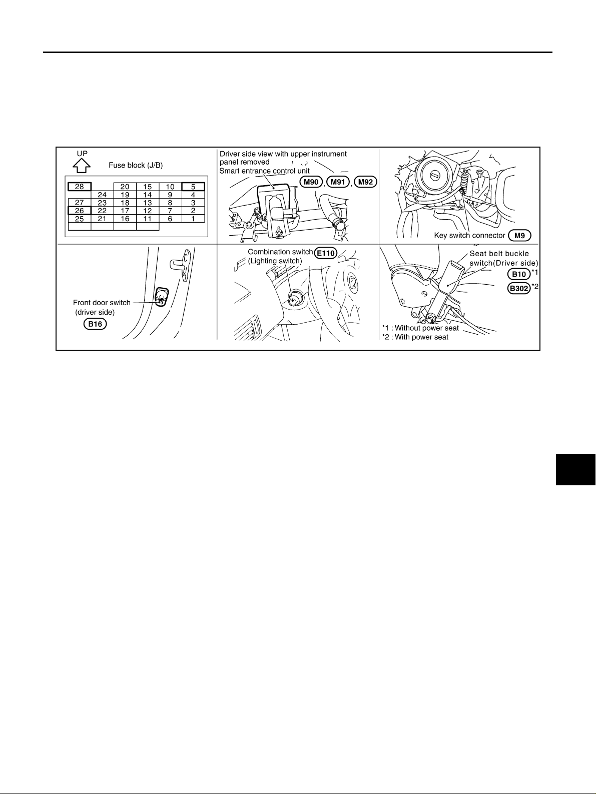
Component Parts and Harness Connector Location AKS00BLS
A
B
C
D
E
F
G
SKIB0509E
H
I
J
DI
L
M
Revision: 2005 March 2005 X-Trail
DI-43
Page 44
WARNING CHIME
Schematic AKS00C35
TKWB0269E
Revision: 2005 March 2005 X-Trail
DI-44
Page 45
WARNING CHIME
Wiring Diagram — CHIME — AKS00BB5
A
B
C
D
E
F
G
DI
H
I
J
L
M
TKWB0188E
Revision: 2005 March 2005 X-Trail
DI-45
Page 46
WARNING CHIME
TKWB0189E
Revision: 2005 March 2005 X-Trail
DI-46
Page 47
WARNING CHIME
A
B
C
D
E
F
G
DI
H
I
J
L
M
TKWB0270E
Revision: 2005 March 2005 X-Trail
DI-47
Page 48
WARNING CHIME
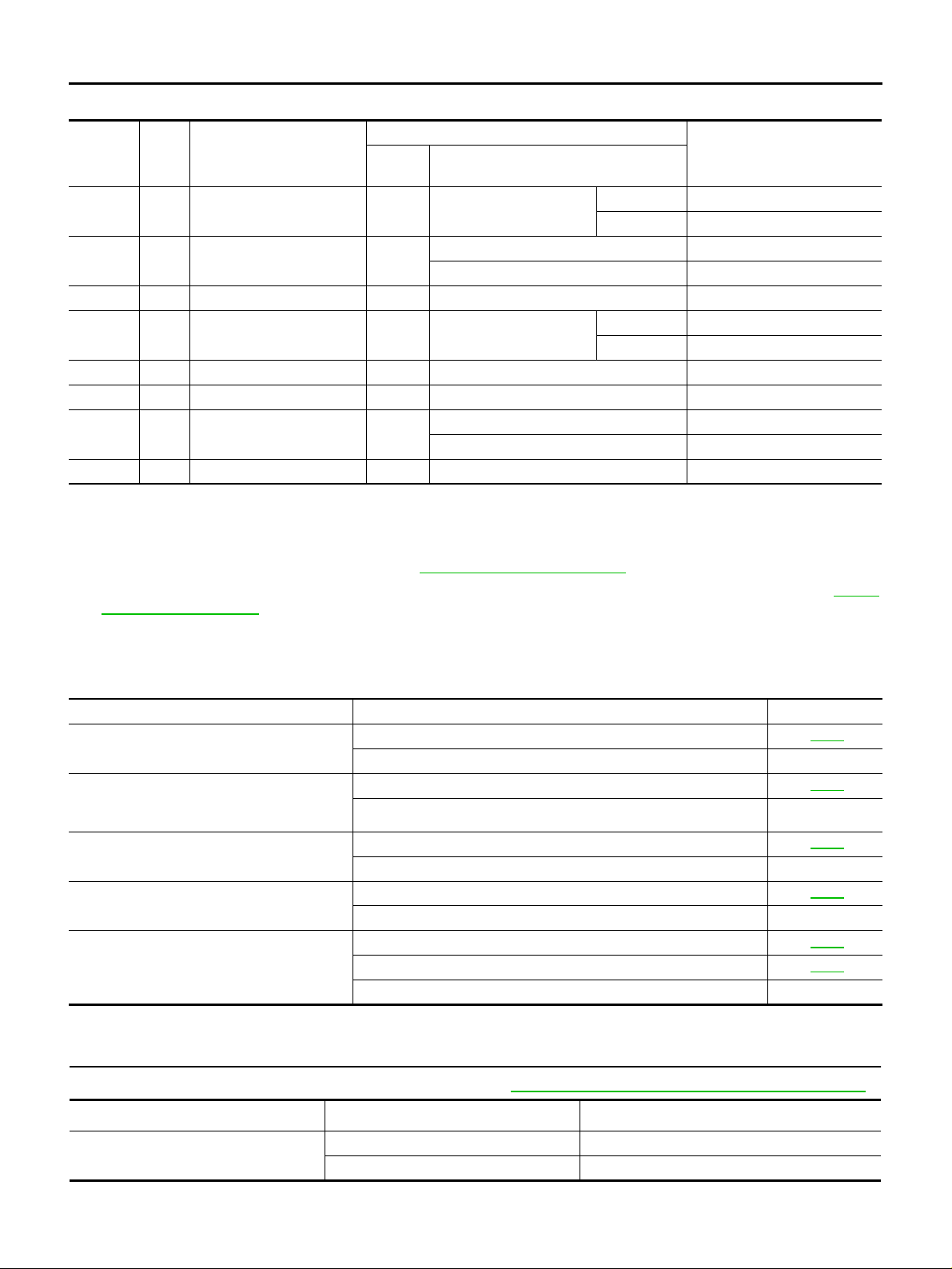
Terminals and Reference Value for Smart Entrance Control Unit AKS00BQR
Terminal
No.
1SB
25 W/L Key switch (Insert) OFF
27 G Ignition switch (ON) ON — Battery voltage
28 BR/W
43 B Ground ON — 0 V
49 L/R Power source (Fuse) OFF — Battery voltage
58 R/L Lighting switch OFF
64 B Ground ON — 0 V
Wire
color
Front door switch
(Driver side)
Seat belt buckle switch
(Driver side)
Item
Ignition
switch
OFF Front door (d river sid e)
Key inserted 12 V
Key removed from ignition key cylinder 0 V
ON Seat belt buckle
Lighting switch is 1ST or 2ND positions 12 V
Lighting switch is OFF position 0 V
Condition
Operation
Reference values
(Approximate values)
Closed 12 V
Open 0 V
Unfastened 0 V
Fastened 12 V
Trouble Diagnosis AKS00BQ8
HOW TO PROCEED WITH TROUBLE DIAGNOSIS
1. Confirm the symptom and customer complaint.
2. Understand the outline of system. Refer to DI-42, "
3. Referring to trouble diagnosis chart, repair or replace the cause of the malfunction. Refer to DI-48,
"SYMPTOM CHART" .
4. Does warning chime system operate normally? If it operates normally, GO TO 5. If not, GO TO 3.
5. INSPECTION END
System Description" .
SYMPTOM CHART
Symptom Diagnoses/Service procedure Reference page
All warning chimes do not activate.
Light warning chime and key warning chime
does not activate
(Seat belt warning chime does activate)
Light warning chime does not activate.
Key warning chime does not activate.
Seat belt warning chime does not activate
Power supply and ground circuit Inspection DI-48
If above systems are OK, replace smart entrance control unit —
Front door switch (driver side) Inspection DI-49
If above systems are OK, replace smart entrance control unit —
Lighting switch input signal Inspection DI-51
If above systems are OK, replace smart entrance control unit —
Key switch insert signal Inspection DI-51
If above systems are OK, replace smart entrance control unit —
Seat belt buckle switch input signal Inspection [without power seat] DI-52
Seat belt buckle switch input signal Inspectio n [wi th pow er se at] DI-54
If above systems are OK, replace smart entrance control unit —
Power Supply and Ground Circuit Inspection AKS00BB8
1. CHECK FUSE
Check for blown smart entrance control unit fuses. Refer to PG-49, "
Unit Power source Fuse No.
Smart entrance control unit
Battery 26
Ignition switch (ON) 5
FUSE BLOCK - JUNCTION BOX (J/B)" .
Revision: 2005 March 2005 X-Trail
DI-48
Page 49
WARNING CHIME
OK or NG
OK >> GO TO 2.
NG >> If fuse is blown, be sure to eliminate cause of malfunction before installing new fuse.
A
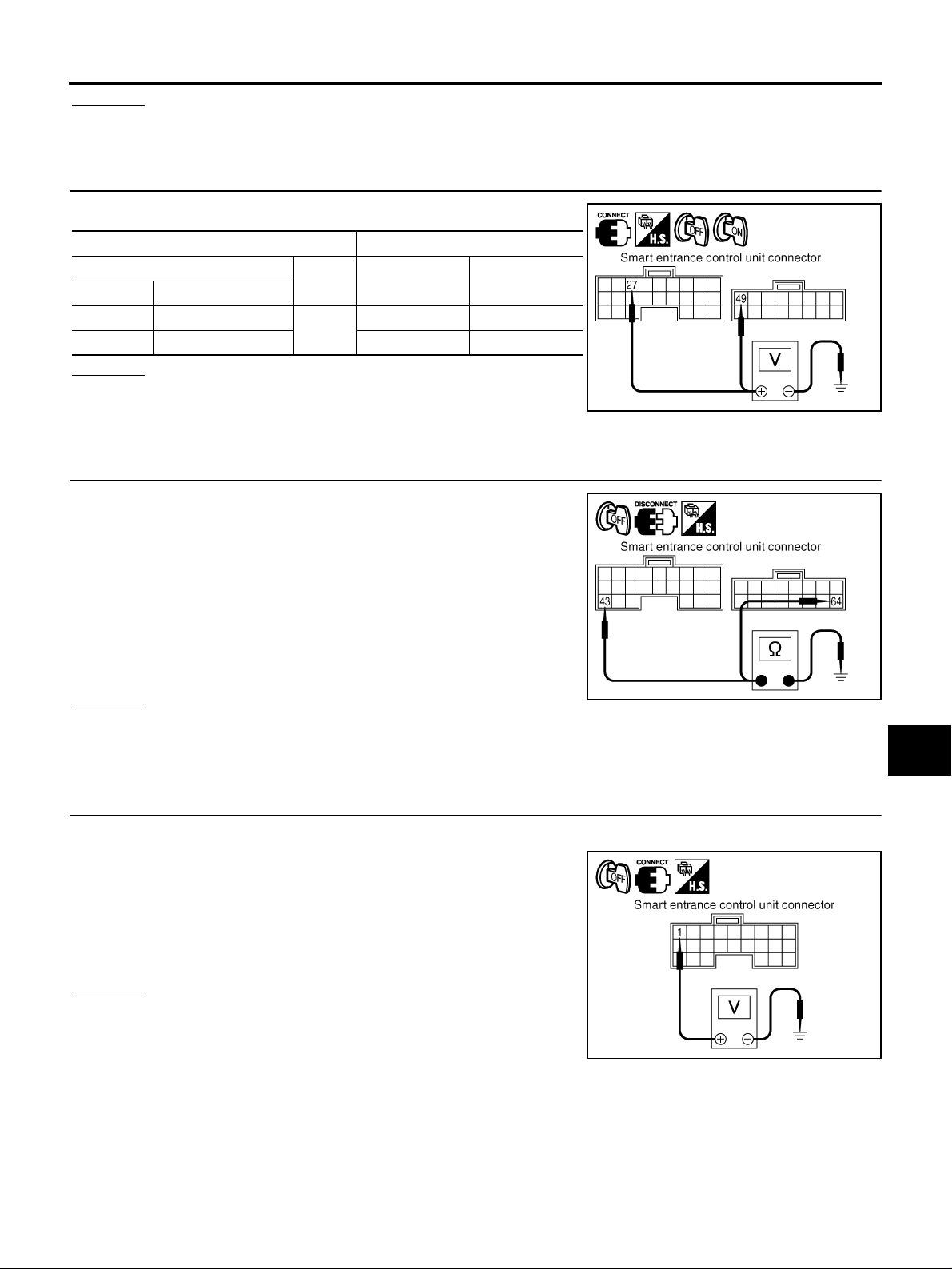
2. CHECK POWER SUPPLY CIRCUIT
Check volt age between smart entrance contr ol unit and grou nd.
Terminals Ignition switch position
(+)
Connector Terminal (Wire color)
M92 49 (L/R)
M91 27 (G) 0 V Battery voltage
(–) OFF ON
Ground
Battery voltage Battery voltage
OK or NG
OK >> GO TO 3.
NG >> Check harness between fuse and smart entrance con-
trol unit.
3. CHECK GROUND CIRCUIT
1. Turn ignition switch OFF.
2. Disconnect smart entrance control unit connecto r.
3. Check continuity between smart entrance control unit harness
connector M91 terminal 43 (B) and ground.
43 (B) – Ground : Continuity should exist.
4. Check continuity between smart entrance control unit harness
connector M92 terminal 64 (B) and ground.
B
C
D
E
SKIB0608E
F
G
H
I
64 (B) – Ground : Continuity should exist.
OK or NG
SKIB0609E
OK >> Power supply and ground circuit are OK.
NG >> Repair ground harness.
Front Door Switch (Driver Side) Inspection AKS00BB9
1. CHECK DOOR SWITCH INPUT SIGNAL
1. Turn ignition switch OFF.
2. Check voltage between smart entrance control unit harness
connector M90 terminal 1 (SB) and ground.
1 (SB) – Ground
When driver door is opened : Approx. 0 V
When driver door is closed : Approx. 12 V
OK or NG
OK >> Front door switch (driver side) is OK.
NG >> GO TO 2.
SKIB0510E
J
DI
L
M
Revision: 2005 March 2005 X-Trail
DI-49
Page 50
WARNING CHIME
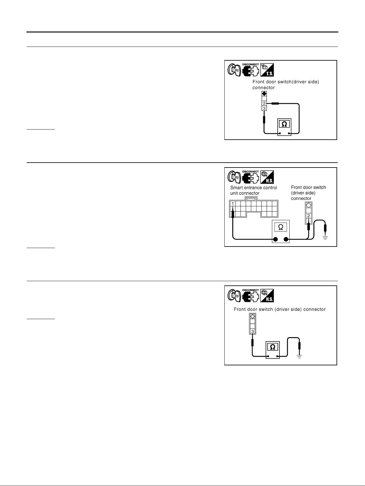
2. CHECK FRONT DOOR SWITCH (DRIVER SIDE)
1. Disconnect fr ont door switch (driver side) connector.
2. Check continui t y be tw ee n fro nt door swi t ch (dr iver si de ) B1 6 ter minals 2 and 3.
2 – 3
When door switch is
released
When door switch is
pushed
OK or NG
OK >> GO TO 3.
NG >> Replace front door switch (driver side).
: Continuity should exist.
: Continuity should not exist.
3. CHECK FRONT DOOR SWITCH CIRCUIT
1. Disconnect smart entrance control unit connector.
2. Check continuity between smart entrance control unit harness
connector M90 terminal 1 (SB) and front door switch (driver
side) harness connector B16 terminal 2 (R).
SKIB0534E
1 (SB) − 2 (R) : Continuity should exist.
3. Check continuity between smart entrance control unit harness
connector M90 terminal 1 (SB) and ground.
1 (SB) – Ground : Continuity should not exist.
OK or NG
OK >> GO TO 4.
NG >> Repair harness or connector.
4. CHECK FRONT DOOR SWITCH GROUND CIRCUIT
Check continuity between front door switch (driver side) harness
connector B16 terminal 3 (B) and ground.
3 (B) – Ground : Continuity should exist.
OK or NG
OK >> Replace smart entrance control unit.
NG >> Repair harness or connector.
SKIB0511E
SKIB0610E
Revision: 2005 March 2005 X-Trail
DI-50
Page 51
WARNING CHIME
Lighting Switch Input Signal Inspection AKS00BBA
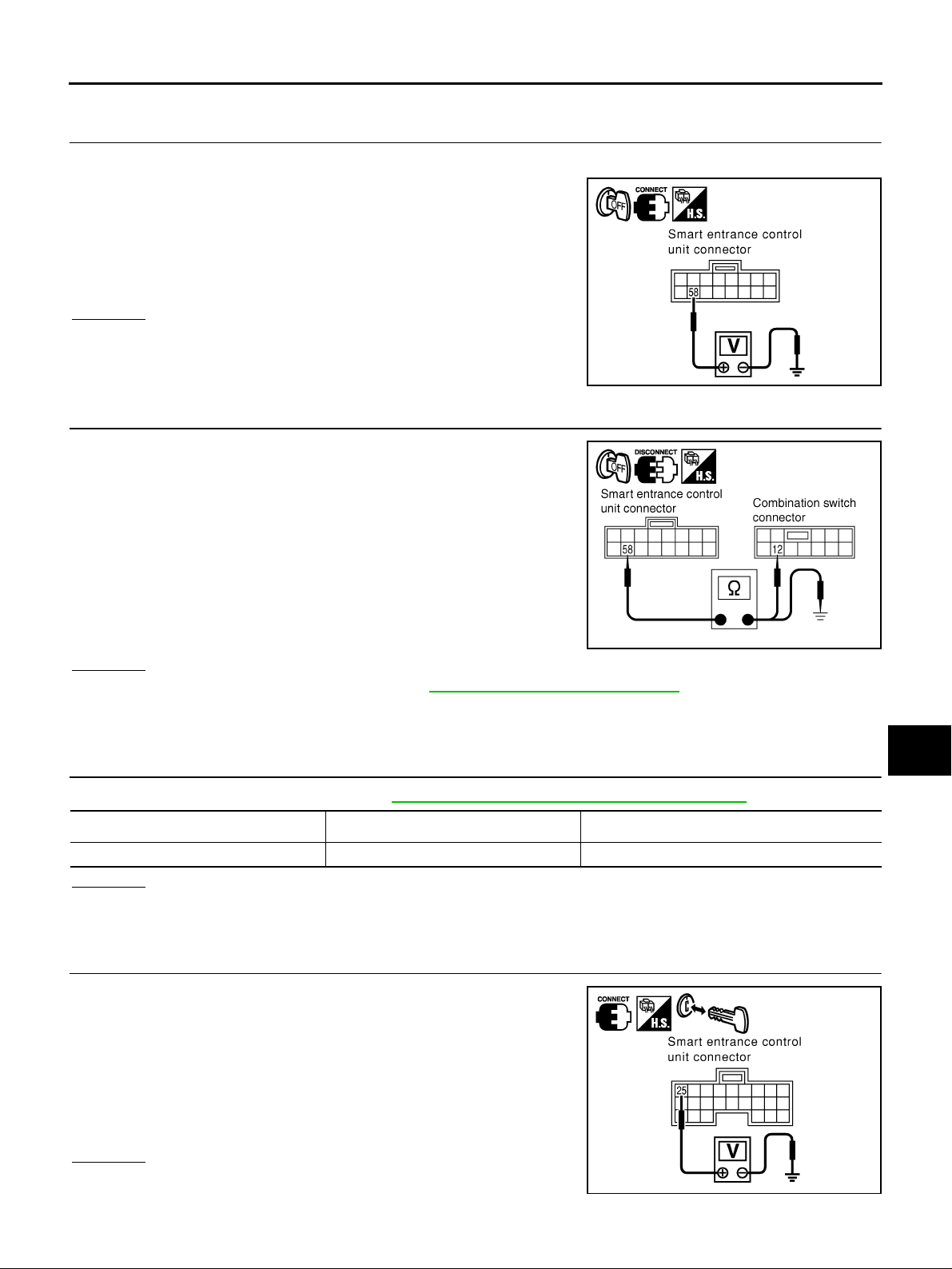
1. CHECK LIGHTING SWITCH INPUT SIGNAL
1. Turn ignition switch OFF.
2. Check voltage between smart entrance control unit harness
connector M9 2 terminal 58 (R/L) and ground.
A
B
58 (R/L) – Ground
Lighting switch (1st or 2nd position) : Approx. 12 V
Lighting switch (OFF) : Approx. 0 V
OK or NG
OK >> Lighting switch is OK.
NG >> GO TO 2.
2. CHECK LIGHTING SWITCH CIRCUIT
1. Disconnect smart entrance control unit connector and combination switch connector.
2. Check continuity between smart entrance control unit harness
connector M92 terminal 58 (R/L) and combination switch harness connector E110 terminal 12 (R/L).
58 (R/L) – 12 (R/L) : Continuity should exist.
3. Check continuity between smart entrance control unit harness
connector M9 2 terminal 58 (R/L) and ground.
58 (R/L) – Ground : Continuity should not exist.
OK or NG
OK >> Check combination switch. Refer to LT-42, "COMBINATION SWITCH" .
NG >> Repair harness or connector.
SKIB0611E
SKIB0512E
C
D
E
F
G
H
I
J
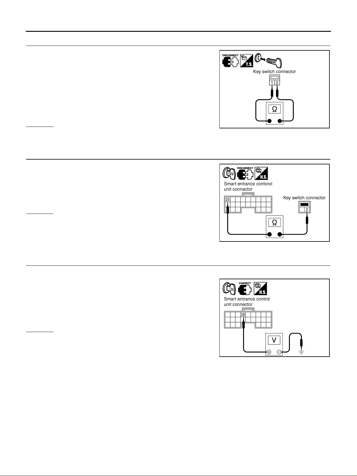
Key Switch Insert Signal Inspection AKS00BBB
1. CHECK FUSE
Check for blown key sw i tc h f us es . Refer to PG-49, "
Unit Power source Fuse No.
Key switch Battery 28
OK or NG
OK >> GO TO 2.
NG >> If fuse is blown, be sure to eliminate cause of malfunction before installing new fuse.
FUSE BLOCK - JUNCTION BOX (J/B)" .
2. CHECK KEY SWITCH INPUT SIGNAL
Check voltage betw ee n s ma rt en tra nc e control unit harne ss connector M91 terminal 25 (W/L) and ground.
25 (W/L) – Ground
When key is inserted to
ignition key cylinder
When key is removed from
ignition key cylinder
OK or NG
OK >> Key switch is OK.
NG >> GO TO 3.
: Approx. 12 V
: Approx. 0 V
SKIB0612E
DI
L
M
Revision: 2005 March 2005 X-Trail
DI-51
Page 52
WARNING CHIME
3. CHECK KEY SWITCH (INSERT)
1. Disconnect key switch connector.
2. Check con tinuity betwee n key switch conn ector M9 termina ls 1
and 2.
1 – 2
When key is inserted to
ignition key cylinder
When key is removed from
ignition key cylinder
: Continuity should
exist.
: Continuity should
not exist.
OK or NG
OK >> GO TO 4.
NG >> Replace key switch.
SKIB0613E
4. CHECK KEY SWITCH CIRCUIT
1. Disconnect smart entrance control unit connector.
2. Check continuity between smart entrance control unit harness
connector M91 termin al 25 (W/L) and key switch harness co nnector M9 terminal 2 (W/L).
25 (W/L) – 2 (W/L) : Continuity should exist.
OK or NG
OK >> Check continuity open between key switch and fuse.
NG >> Repair harness or connector.
SKIB0614E
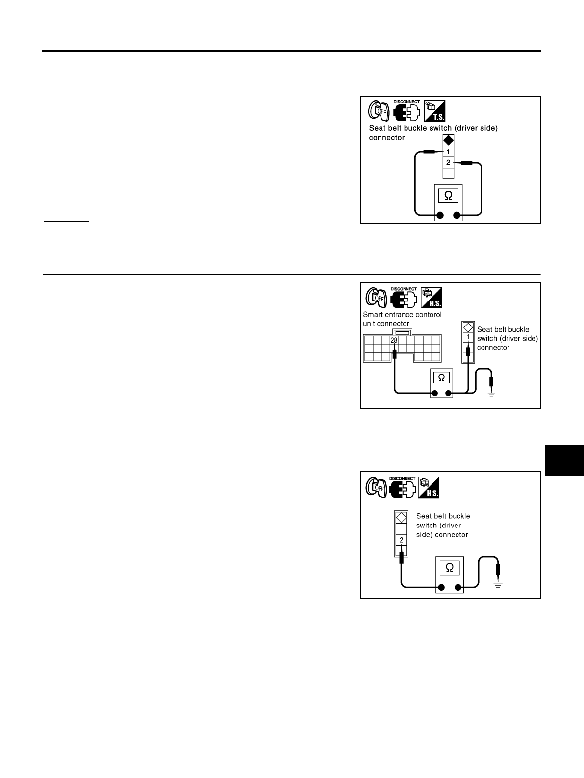
Seat Belt Buckle Switch Input Signal Inspection [Without Power Seat] AKS00BQK
1. CHECK SEAT BELT BUCKLE SWITCH INPUT SIGNAL
1. Turn ignition switch ON.
2. Check voltage between smart entrance control unit harness
connector M91 terminal 28 (BR/W) and ground.
28 (BR/W) – Ground
When seat belt is fastened : Approx. 12 V
When seat belt is unfastened : Approx. 0 V
OK or NG
OK >> Seat belt buckle switch is OK.
NG >> GO TO 2.
SKIB0550E
Revision: 2005 March 2005 X-Trail
DI-52
Page 53
WARNING CHIME
2. CHECK SEAT BELT BUCKLE SWITCH
1. Turn ignition switch OFF.
2. Disconnect seat belt buckle switch (driver side) connector.
3. Check continuity seat belt buckle switch (driver side) connector
terminals 1 and 2.
1 – 2
When seat be lt is fastened : Continuity should
not exist.
When seat belt is unfastened : Continuity should
exist.
OK or NG
OK >> GO TO 3.
NG >> Replace seat belt buckle switch (driver side).
3. CHECK SEAT BELT BUCKLE SWITCH CIRCUIT
1. Disconnect smart entrance control unit connecto r.
2. Check continuity between smart entrance control unit harness
connector M9 1 terminal 28 (BR/W) an d seat belt buckle swit ch
(driver side) harness connector B10 terminal 1 (BR/W).
28 (BR/W) – 1 (BR/W) : Continuity should exist.
3. Check continuity between smart entrance control unit harness
connector M91 terminal 28 (BR/W) and ground.
28 (BR/W) – Ground : Continuity should not exist.
OK or NG
OK >> GO TO 4.
NG >> Repair harness or connector.
A
B
C
D
SKIB0677E
E
F
G
H
I
SKIB0551E
J
4. CHECK SEAT BELT BUCKLE SWITCH GROUND CIRCUIT
Check continuity between seat belt buck le switch (driver side) harness connector B10 terminal 2 (B) and ground.
2 (B) – Ground : Continuity should exist.
OK or NG
OK >> Replace smart entrance control unit.
NG >> Repair harness or connector.
DI
L
M
SKIB0615E
Revision: 2005 March 2005 X-Trail
DI-53
Page 54
WARNING CHIME
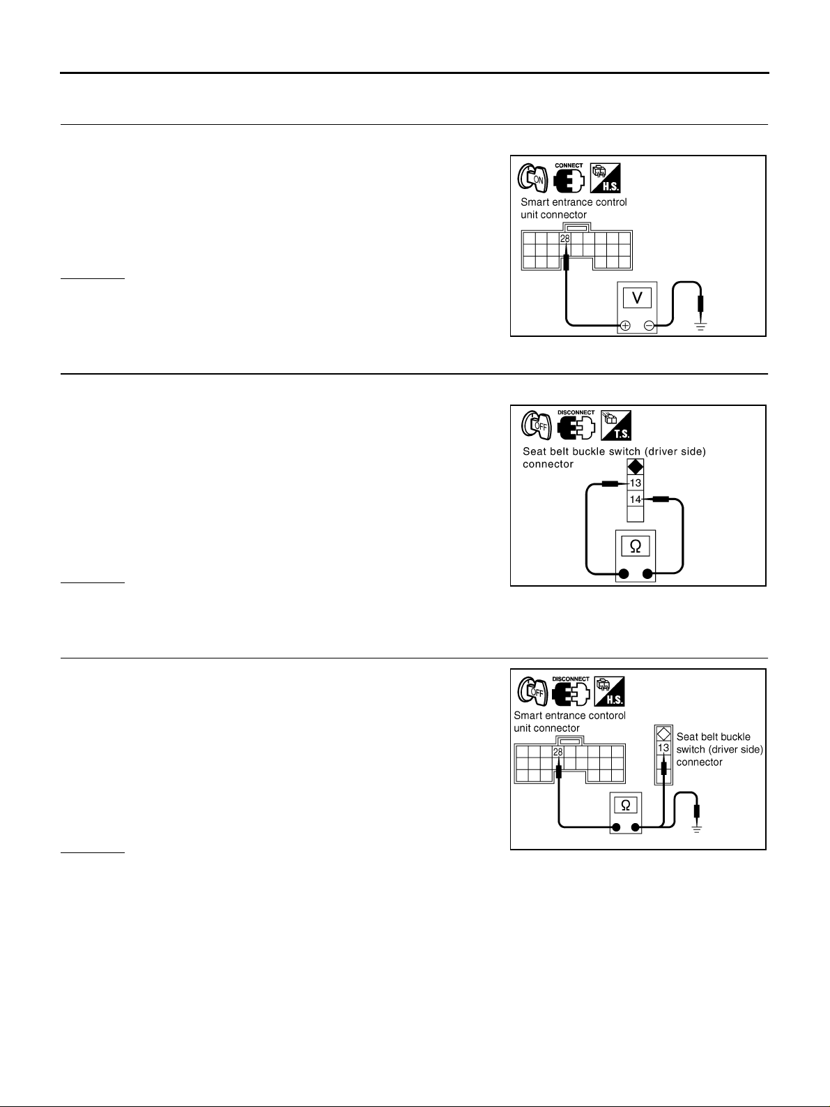
Seat Belt Buckle Switch Input Signal Inspection [With Power Seat] AKS00BQL
1. CHECK SEAT BELT BUCKLE SWITCH INPUT SIGNAL
1. Turn ignition switch ON.
2. Check voltage between smart entrance control unit harness
connector M91 terminal 28 (BR/W) and ground.
28 (BR/W) – Ground
When seat belt is fastened : Approx. 12 V
When seat belt is unfastened : Approx. 0 V
OK or NG
OK >> Seat belt buckle switch is OK.
NG >> GO TO 2.
SKIB0550E
2. CHECK SEAT BELT BUCKLE SWITCH
1. Turn ignition switch OFF.
2. Disconnect seat belt buckle swit ch (driver side) connector.
3. Check continuity seat belt buckle switch (driver side) connector
terminals 13 and 14.
13 – 14
When seat belt is fastened : Continuity should
not exist.
When seat belt is unfastened : Continuity should
exist.
OK or NG
OK >> GO TO 3.
NG >> Replace seat belt buck le switch (driver side).
3. CHECK SEAT BELT BUCKLE SWITCH CIRCUIT
1. Disconnect smart entrance control unit connector.
2. Check continuity between smart entrance control unit harness
connector M91 term inal 28 (BR/W) and seat b elt buckle switch
(driver side) harness connector B302 terminal 13 (R).
28 (BR/W) – 13 (R) : Continuity should exist.
3. Check continuity between smart entrance control unit harness
connector M91 terminal 28 (BR/W) and ground.
28 (BR/W) – Ground : Continuity should not exist.
OK or NG
OK >> GO TO 4.
NG >> Repair harness or connector.
SKIB0552E
SKIB0554E
Revision: 2005 March 2005 X-Trail
DI-54
Page 55
WARNING CHIME
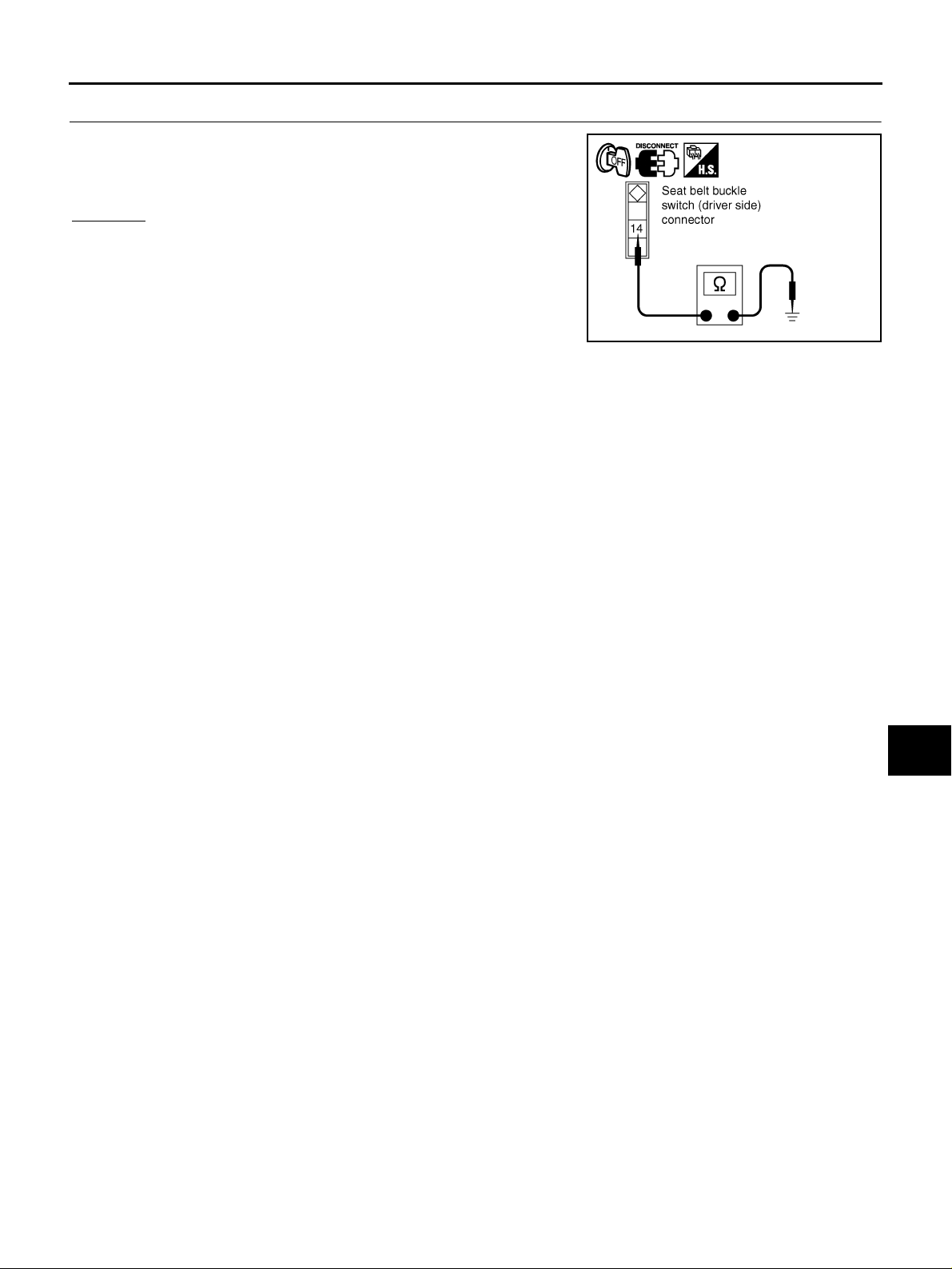
4. CHECK SEAT BELT BUCKLE SWITCH GROUND CIRCUIT
Check continuity between seat belt buck le switch (driver side) harness connector B302 terminal 14 (OR) and grou nd.
14 (OR) – Ground : Continuity should exist.
OK or NG
OK >> Replace smart entrance control unit.
NG >> Repair harness or connector.
A
B
C
D
SKIB0553E
E
F
G
H
DI
I
J
L
M
Revision: 2005 March 2005 X-Trail
DI-55
Page 56
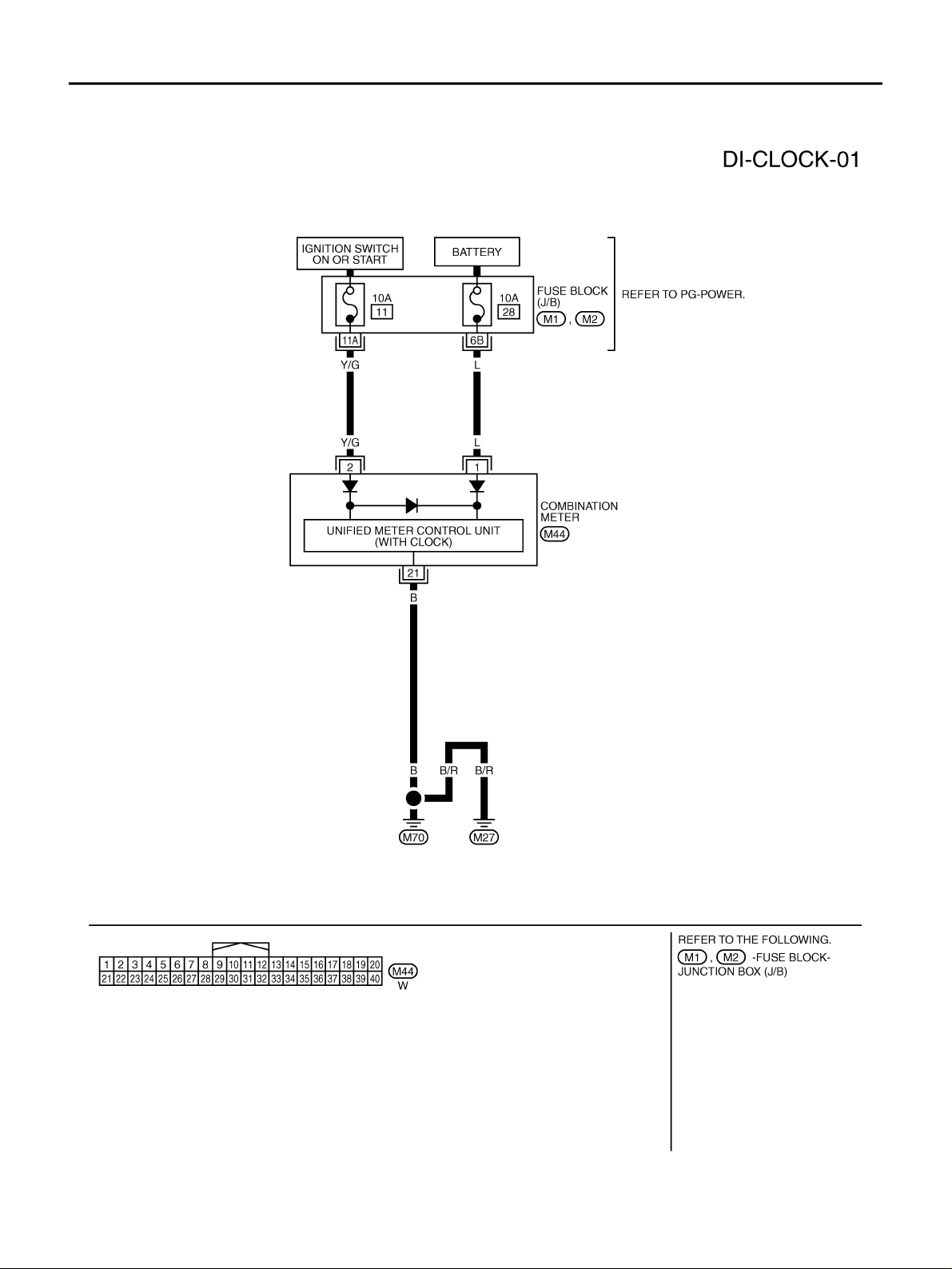
CLOCK
CLOCK PFP:25820 Wiring Diagram — CLOCK — AKS00BBC
TKWA1859E
Revision: 2005 March 2005 X-Trail
DI-56
 Loading...