

Page 1

ACCELERATOR CONTROL SYSTEM
B ENGINE
A
ACC
SECTION
ACCELERA T OR CONTROL SYSTEM
CONTENTS
ACCELERATOR CONTROL SYSTEM ...................... 2
Removal and Installation .......................................... 2
QR20DE ................................................................ 2
YD22DDTI ............................................................. 2
REMOVAL ............................................................. 2
INSTALLATION ..................................................... 3
INSPECTION AFTER INSTALLATION ................. 3
SERVICE DATA AND SPECIFICATIONS (SDS) ........ 4
Tightening Torque ..................................................... 4
C
D
E
F
G
H
I
J
K
M
L
ACC-1
Page 2
ACCELERATOR CONTROL SYSTEM
ACCELERATOR CONTROL SYSTEM
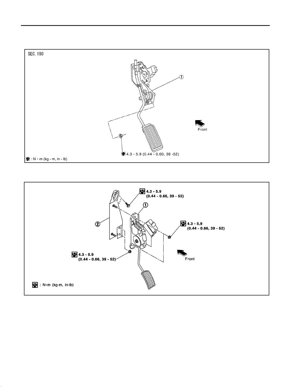
Removal and Installation
QR20DE
1Acceleratorpedalassembly
PFP:18005
EBS003CH
KBIA0307E
YD22DDTI
SBIA0120E
Accelerator pedal assembly (work
1
unit)
2Acceleratorpedalbracket
REMOVAL
1. Remove harness connector.
2. Loosen nuts, and remove accelerator pedal assembly.
CAUTION:
● Do not disassemble the accelerator pedal assembly. Do no t remove the sensors and the switches
from the assembly.
● Avoid impact from dropping etc. during handling.
● Be careful to keep the assembly away from water.
ACC-2
Page 3

ACCELERATOR CONTROL SYSTEM
● Do not adjust the adjusting screw (painted white) of the accelerator work unit. (YD22DDTi)
● When the harness connector of the accelerator sensor is disconnected, perform ″Accelerator
Pedal Released Position Learning″.Referto″Basic Service Procedure″ in EC section.
A
INSTALLATION
Install in the reverse order of removal.
INSPECTION AFTER INSTALLATION
● Check that the accelerator pedal moves smoothly within the whole operation range.
● Check that the accelerator pedal securely returns to the original position.
● For the electrical inspection of the accelerator pedal assembly, refer to EC-154, "DTC P0121 APP SEN-
SOR" (WITH EURO-OBD) a nd EC-484, "DTC P0121 APP SENSOR" (WITHOUT EURO-OBD).
(QR20DE)
● For the electrical inspection of the accelerator work unit, refer to EC-7 15, "DTC P0120 ACCELERATOR
PEDAL POSITION SENSOR" and EC-783, "DTC P1510 ACCELERATOR PEDAL RELEASED POSITION SWITCH" .(YD22DDTi)
● Check that the drum of the accelerator work unit can be fully opened. (YD22DDTi)
ACC
C
D
E
F
G
H
I
K
M
J
L
ACC-3
Page 4

SERVICE DATA AND SPECIFICATIONS (SDS)
SERVICE DATA AND SPECIFICATIONS (SDS)
Tightening Torque
Accelerator pedal assembly 4.3 - 5.9 (0.44 - 0.60, 39 - 52)
Accelerator pedal assembly (work unit) (YD22DDTi) 4.3 - 5.9 (0.44 - 0.60, 39 - 52)
Accelerator pedal bracket (YD22DDTi) 4.3 - 5.9 (0.44 - 0.60, 39 - 52)
PFP:00030
EBS003CI
Unit: N·m (Kg-m, in-lb)
ACC-4
Page 5

AUTOMATIC TRANSAXLE
CTRANSMISSION/TRANSAXLE
A
B
SECTION
CONTENTS
PRECAUTIONS .......................................................... 5
Precautions for Supplemental Restraint System
(SRS) “AIR BAG” and “SEAT BELT PRE-TEN-
SIONER” .................................................................. 5
PrecautionsforOnBoardDiagnostic(EURO-OBD)
System of A/T and Engine — Euro-OBD — ............. 5
Precautions For Trouble Diagnosis .......................... 5
Precautions For Harness Repair .............................. 5
Precautions .............................................................. 6
Service Notice or Precautions .................................. 7
Wiring Diagrams and Trouble Diagnosis . ................. 8
PREPARATION ........................................................... 9
Special Service Tools ............................................... 9
Commercial Service Tools .......................................11
A/T FLUID ................................................................. 13
Checking A/T Fluid ................................................. 13
Changing A/T Fluid ................................................ 13
OVERALL SYSTEM ................................................. 14
A/T Electrical Parts Location .................................. 14
Circuit Diagram ...................................................... 16
Cross-sectional View .............................................. 17
Hydraulic Control Circuit ........................................ 18
Shift Mechanism ..................................................... 19
Control System ....................................................... 27
Control Mechanism ................................................ 29
Control Valve .......................................................... 33
EURO-OBD
TROUBLE DIAGNOSIS — INDEX ........................... 35
Alphabetical & P No. Index for DTC ....................... 35
ON BOARD DIAGNOSTIC SYSTEM DESCRIP-
TION .......................................................................... 37
Introduction ............................................................ 37
EURO-OBD Function for A/T System .................... 37
One or Two Trip Detection Logic of EURO-OBD ... 37
EURO-OBD Diagnostic Trouble Code (DTC) ......... 37
Malfunction Indicator lamp (MIL) ............................ 41
CONSULT-II ........................................................... 41
Diagnostic P rocedure Without CONSULT-II ........... 50
AUT OMATIC TRANSAXL E
TROUBLE DIAGNOSIS — INTRODUCTION ........... 5 6
Introduction ............................................................. 56
Work Flow ............................................................... 61
TROUBLE DIAGNOSIS — BASIC INSPECTION .... 64
A/T Fluid Check ...................................................... 64
Stall T est ................................................................. 65
Line Pressure Test .................................................. 68
Road Test ............................................................... 69
TROUBLE DIAGNOSIS — GENERAL DESCRIP-
TION .......................................................................... 86
Symptom Chart ....................................................... 86
TCM Terminals and Reference Value ...................125
CAN COMMUNICATION .........................................129
System Description ...............................................129
DTC P0705 PARK/NEUTRAL POSITION (PNP)
SWITCH ..................................................................130
Description ............................................................130
Wiring Diagram — AT — PNP/SW .......................132
Diagnostic Procedure ...........................................133
Component Inspection ..........................................135
DTC P0710 A/T FLUID TEMPERATURE SENSOR
CIRCUIT ..................................................................136
Description ............................................................136
Wiring Diagram — AT — FTS ..............................138
Diagnostic Procedure ...........................................139
Component Inspection ..........................................141
DTC P0720 VEHICLE SPEED SE NSOR·A/T (REV-
OLUTION SENSOR ) ...............................................142
Description ............................................................142
Wiring Diagram — AT — VSSA/T ........................144
Diagnostic Procedure ...........................................145
DTC P 0725 ENGINE SPEED SIGNAL ...................147
Description ............................................................147
Wiring Diagram — AT — ENGSS .........................148
Diagnostic Procedure ...........................................149
DTC P0731 A/T 1ST GEAR FUNCTION ................151
Description ............................................................151
Wiring Diagram — AT — 1ST ...............................154
Diagnostic Procedure ...........................................155
Component Inspection ..........................................156
AT
D
E
F
G
H
I
J
K
L
M
AT-1
Page 6

DTC P0732 A/T 2ND GEAR FUNCTION ................158
Description ............................................................158
Wiring Diagram — AT — 2ND ..............................161
Diagnostic Procedure ...........................................162
Component Inspection ..........................................163
DTC P0733 A/T 3RD GEAR FUNCTION ................165
Description ............................................................165
Wiring Diagram — AT — 3RD ..............................168
Diagnostic Procedure ...........................................169
Component Inspection ..........................................170
DTC P0734 A/T 4TH GEAR FUNCTION ................172
Description ............................................................172
Wiring Diagram — AT — 4TH ...............................175
Diagnostic Procedure ...........................................176
Component Inspection ..........................................179
DTC P0740 TORQUE CONVERTER CLUTCH
SOLENOID VALVE .................................................181
Description ............................................................181
Wiring Diagram — AT — TCV ..............................183
Diagnostic Procedure ...........................................184
Component Inspection ..........................................185
DTC P0745 LINE PRESSURE SOLENOID VALVE. 186
Description ............................................................186
Wiring Diagram — AT — LPSV ............................188
Diagnostic Procedure ...........................................189
Component Inspection ..........................................191
DTC P 0750 SHIFT SOLENOID VALVE A ...............193
Description ............................................................193
Wiring Diagram — AT — SSV/A ...........................195
Diagnostic Procedure ...........................................196
Component Inspection ..........................................197
DTC P 0755 SHIFT SOLENOID VALVE B ...............198
Description ............................................................198
Wiring Diagram — AT — SSV/B ...........................200
Diagnostic Procedure ...........................................201
Component Inspection ..........................................202
DTC P1705 ACCELERATOR PEDAL P OSITION
(APP) SE N SOR . ......................................................203
Description ............................................................203
Wiring Diagram — AT — TPS ..............................205
Diagnostic Procedure ...........................................206
DTC P1760 OVERRUN CLUTCH SOLENOID
VALVE ... ... ......... ...................... ......... ......... ..............208
Description ............................................................208
Wiring Diagram — AT — OVRCSV ......................210
Diagnostic Procedure ...........................................211
Component Inspection ..........................................212
DTC U10 00 CAN COMMUNICATION LINE ............213
Description ............................................................213
On Board Diagnosis Logic ....................................213
..............................................................................213
Wiring Diagram — AT ...........................................214
Diagnostic Procedure ...........................................215
DTC BATT/FLUID TEMP SEN (A/T FLUID TEMP
SENSOR CIRCUIT AND TCM POWER SOURCE).216
Description ............................................................216
Wiring Diagram — AT — BA/FTS .........................218
Diagnostic Procedure ............................................219
Component Inspection . .........................................221
DTC VEHICLE SPEED SENSOR MTR ...................222
Description ............................................................222
Wiring Diagram — AT — VSSMTR .......................224
Diagnostic Procedure ............................................225
DTC CONTROL UNIT (RAM), CONTROL UNIT
(ROM) ......................................................................226
Description ............................................................226
Diagnostic Procedure ............................................227
DTC CONTROL UNIT(EEPROM) ...........................228
Description ............................................................228
Diagnostic Procedure ............................................229
TROUBLE DIAGNOSES FOR SYMPTOMS ...........230
..............................................................................230
1. O/D OFF Indicator Lamp Does Not Come On ..232
2. Engine Cannot Be Started In “P” and “N” Position.233
3. In “P” Position, Vehicle Moves Forward Or Back-
ward When Pushed ...............................................234
4. In “N” Position, Vehicle Moves . .........................234
5. L arge Shock. “N” → “R” Position ......................236
6. VehicleDoes Not CreepBackwardIn “R” Position.237
7. Vehicle Does Not Creep Forward In “D”, “2” Or
“1” Position ............................................................240
8. Vehicle Cannot Be Started From D
9. A/T Does Not Shift: D
down: D
4 → D2 .....................................................244
10. A/T Does Not Shift: D
11. A/T Doe s No t S hift: D
1 → D2 Or Does Not Kick-
2 → D3 ..........................246
3 → D4 ...........................249
1 .................242
12. A/T Does Not Perform Lock-up .......................252
13. A/T Does Not Hold Lock-up Cond ition ............253
14. Lock-up Is Not Released .................................254
15. Engine Speed Does Not Return To Idle (Light
Braking D
16. Vehicle Does Not Start From D
17. A/T Does Not Shift: D
4 → D3 ).................................................255
1 .....................257
4 → D3 ,WhenOverdrive
Control S witch “ON” → “OFF” ...............................258
18. A/T Does Not Shift: D
3 → 22 ,WhenSelector
Lever “D” → “2” Position .......................................258
19. A/T Does Not Shift: 2
2 → 11 ,WhenSelector
Lever “2” → “1” Position ........................................259
20. Vehicle Does Not Decelerate By Engine Brake.259
21. TCM Self-diagnosis Does Not Activate (PNP &
Overdrive Control Switches, and Throttle Position
Sensor Circuit Checks) .........................................260
EXC.F/EURO-OBD
ON BOARD DIAGNOSTIC SYSTEM DESCRIP-
TION ........................................................................267
CONSULT-II ..........................................................267
Diagnostic P roc edure Without CONSULT-II .........273
TROUBLE DIAGNOSIS — INTRODUCTION .........279
Introduction ...........................................................279
Work Flow . ............................................................284
TROUBLE DIAGNOSIS — BASIC INSPECTION ...286
A/T Fluid Check ....................................................286
Stall T est ................................................................287
AT-2
Page 7

Line P ressure Test ...............................................290
Road Test .............................................................291
TROUBLE DIAGNOSIS — GENERAL DESCRIP-
TION ........................................................................308
Symptom Chart ....................................................308
TCM Terminals and Reference Value ...................347
CAN COMMUNICATION ........................................351
System Description ..............................................351
TROUBLE DIAGNOSES FOR SYMPTOMS ..........352
.............................................................................352
1. O/D OFF Indicator Lamp Does Not Come On . 354
2. Engine Cannot Be Started In “P”and “N” Pos ition.355
3. In “P” Position, Vehicle Moves Forward Or Back-
ward When Pushed ..............................................356
4. In “N” Position, Vehicle Moves .........................356
5. Large Shock. “N” → “R” Position ......................358
6.VehicleDoes Not CreepB ac k w ard In“R” Position.359
7. Vehicle Does Not Creep Forward In “D”, “2” O r
“1” Position ...........................................................362
8. Vehicle Cannot Be Started From D
9. A/T Does Not S hift: D
down: D
4 → D2 .....................................................366
10. A/ T Does Not Shif t: D
11. A/T Doe s No t S hift: D
1 → D2 Or Does Not Kick-
2 → D3 .........................368
3 → D4 ..........................371
1 .................364
12. A/ T Does Not Per form Lock-up ......................374
13. A/ T Does Not Hold Lock-up Condition ...........375
14. Lock-up Is Not Released ................................376
15. Engine Speed Does Not Return To Idle (Light
Braking D
16. Vehicle Does Not Start From D
17. A/T Does Not Shift: D
4 → D3 )................................................377
1 .....................379
4 → D3 ,WhenOverdrive
Control Switch “ON” → “OFF” ..............................380
18. A/ T Does Not Shift: D
3 → 22 ,WhenSelector
Lever “D” → “2” Position ......................................380
19. A/ T Does Not Shif t: 2
2 → 11 ,WhenSelector
Lever “2” → “1” Position .......................................381
20. Vehicle Does Not D ec elerate By Engine Brake.381
21. TCM Self-diagnosis Does Not Act ivate (PNP &
Overdrive Control Sw itc hes, and Throttle Pos ition
Sensor Circuit Checks) ........................................382
ALL
MAIN POWER SUPPLY AND GROUND CIRCUIT. 389
Wiring Di agram — AT — MAIN ............................389
Diagnostic Procedure ...........................................390
VEHICLE SPEED SENSOR·A/T (REVOLUTION
SENSOR) ................................................................392
Description ...........................................................392
Wiring Diagram — AT — VSSA/T ........................394
Diagnostic Procedure ...........................................395
DTC VEHICLE SPEED SENS OR MTR ..................397
Description ...........................................................397
Wiring Di agram — AT — VSSMTR ......................399
Diagnostic Procedure ...........................................400
ACCELE RATOR PEDAL POSITION (APP) SEN-
SOR ........................................................................401
Description ...........................................................401
Wiring Diagram — AT — TPS ..............................403
Diagnostic Procedure ...........................................404
SHIFT SOLENOID VALVE A ..................................406
Description ............................................................406
Wiring Diagram — AT — SSV/A ...........................408
Diagnostic Procedure ...........................................409
Component Inspection ..........................................410
SHIFT SOLENOID VALVE B ..................................411
Description ............................................................411
Wiring Diagram — AT — SSV/B ...........................413
Diagnostic Procedure ...........................................414
Component Inspection ..........................................415
OVERRUN CLUTC H SOLENOID VALVE ...............416
Description ............................................................416
Wiring Diagram — AT — OVRCSV ......................418
Diagnostic Procedure ...........................................419
Component Inspection ..........................................420
TORQUE CONVERTER CLUTCH SOLENOID
VALVE ...... ... ......... ...................... ...... ... ......... ...........421
Description ............................................................421
Wiring Diagram — AT — TCV ..............................423
Diagnostic Procedure ...........................................424
Component Inspection ..........................................425
BATT/FLUID TEMP SEN (A/T FLUID TEMP SEN-
SOR CIRCUIT AND TCM POWER SOURCE) .......426
Description ............................................................426
Wiring Diagram — AT — BA/FTS .........................428
Diagnostic Procedure ...........................................429
Component Inspection ..........................................431
ENGINE SPEED SIGNAL .......................................432
Description ............................................................432
Wiring Diagram — AT — ENGSS .........................433
Diagnostic Procedure ...........................................434
LINE PRESSURE SOLENOID VALVE ...................436
Description ............................................................436
Wiring Diagram — AT — LPSV ............................438
Diagnostic Procedure ...........................................439
Component Inspection ..........................................441
CAN CAM MUNICATION LINE ................................443
Description ............................................................443
On Board Diagnosis Logic ....................................443
Self-Diagnosis Code Confirmation Procedure ......443
Wiring Diagram — AT — CAN ..............................444
Diagnostic Procedure ...........................................445
A/T SHIFT LOCK SYSTEM ....................................446
Description ............................................................446
Shift Lock System Electrical Parts Location .........446
Wiring Diagram — SHIFT — ................................447
Diagnostic Procedure ...........................................448
KEY INTERLOCK CABLE ......................................452
Components .........................................................452
Removal ...............................................................452
Installation ............................................................453
ON-VEHICLE SERVICE ..........................................454
Control Valve Assembly and Accumulators ..........454
Control Cable Adjustment .....................................456
Park/Neutral Position (PNP) Switch Adjustment ..456
A
B
AT
D
E
F
G
H
I
J
K
L
M
AT-3
Page 8

Differential Side Oil Seal Replacement .................457
Revolution Sensor Re placement ..........................457
REMOVAL AND INSTAL LATION ...........................458
Removal ...............................................................458
Installation .............................................................459
OVERHAUL ......................................... ...... ..............461
Components .........................................................461
Oil Ch a nnel ............................... ............................464
Locations of Adjusting Shims, Needle Bearings,
Thrust Washers and Snap Rings ..........................465
DISASSEMBLY .......................................................466
Disassembly .........................................................466
REPAIR FOR COMPONENT PARTS ......................482
Manual Shaft ........................................................482
Oil Pump ..... ...... ...................................... ..............485
Control Valve Assembly ........................................489
Control Valve Upper Body ....................................498
Control Valve Lower Body ....................................502
Reverse Clutch .....................................................504
High Clutch ...........................................................507
Forward and Overrun Clutches ............................512
Low & Reverse Brake ...........................................518
Rear Internal Gear, Forward Clutch Hub and Over-
run Clutch Hub ......................................................521
OutputShaft,IdlerGear, R educ tionPinionGearand
Bearing Retainer ...................................................525
Band Servo Piston Assembly ...............................530
Final Drive ............................................................535
ASSEMBLY .............................................................540
Assembly (1) .........................................................540
Adjustment (1) .......................................................541
Assembly (2) .........................................................546
Adjustment (2) .......................................................553
Assembly (3) .........................................................556
SERVICE DA TA AND SPECIFICATIONS (SDS) ....563
General Specifications ..........................................563
Shift Schedule .......................................................563
Stall Revolution .....................................................563
Line P ressure ........................................................563
Control Valves .......................................................564
Accumulator ..........................................................564
Clutch and Brakes .................................................564
Final Drive .............................................................566
Planetary Carrier and Oil Pump ............................567
Input Shaft .............................................................568
Reduction Pinion Gear ..........................................568
Band Servo ...........................................................569
Output Shaft ..........................................................569
Bearing Retainer ...................................................569
Total End Pla y . . .. . . .. . .. . .. . . .. . .. . . .. . .. . . .. . .. . . .. . .. . . .. . .. . . .. . .569
Reverse Clutch End Play ......................................570
Removal and Installation .......................................570
Shift Solenoid Valves ............................................570
Solenoid Valves ....................................................570
A/T Fluid Temperature Sensor ..............................570
Revolution Sensor .................................................571
Dropping Resistor .................................................571
AT-4
Page 9
PRECAUTIONS
PRECAUTIONS PFP:00001
Precautions for Supplemental Restraint System (SRS) “AI R BAG” and “SEAT
BELT PRE-TENSIONER”
ECS004Q0
A
The Supplemental Restraint System such as “AIR BAG” and “SEAT BELT PRE-TENSIONER”, used along
with a front seat belt, helps to reduce the risk or severity of injury to the driver and front passenger for certain
types of collision. Information necessary to service the system safely is included in the SRS and SB section of
this Service Manual.
WARNING:
● To avoid rendering the SRS in operative, which could increase the risk o f personal injury or death
in the event of a collision which would result in air bag inflation, all maintenance must be performed by an authorized NISSAN/INFINITI dealer.
● Improp er maintenance, including incorrect removal and installation of the SRS, can lead to per-
sonal injury caused by unintentional activation of the system. For removal of Spiral Cable and Air
Bag Module, see the SRS section.
● Do not use electrical test equipment on any circuit related to the SRS unless instructed to in this
Service Manual. SRS wiring harnesses can be identified by y ellow harness connectors.
Precautions for On Board Diagnostic (EURO-OBD) System of A/T and Engine —
Euro-OBD —
The ECM has an on board diagnostic system. It will light up the malfunction indicator lamp (MIL) to warn the
driver of a malfunction causing emission deterioration.
CAUTION:
● Be sure to turn the ignition switch “OFF” and disconnect the negative battery terminal before any
repair or inspection work. The open/short circuit o f related switches, sensors, solen oid valves,
etc. will cause the MIL to light up.
● Be sure to connect and lock the connectors securely after work. A loose (unlocked) connector will
cause the MIL to light up due to an open circuit. (Be sure the connector is free from water, grease,
dirt, bent terminals, etc.)
● Be sure to route and secure the harnesses properly after work. Interference of the harness with a
bracket, etc. may cause the MIL to light up due to a short circuit.
● Be sure to connect rubber tubes properly after work. A misconnected or disconnected rubber tube
may cause the MIL to light up due to a malfunction of the EGR system or fuel injection system, etc.
● Be sure to erase the unnecessary malfunction information (repairs completed) from the TCM and
ECM before returning the vehicle to the customer.
ECS004Q1
B
AT
D
E
F
G
H
I
J
K
Precautions For Trouble Diagnosis
CAN SYSTEM
● Do not apply voltage of 7.0V or h igher to the measurement terminals.
● Use the tester with its open terminal voltage being 7.0V or less.
Precautions For Harness Repair
CAN SYSTEM
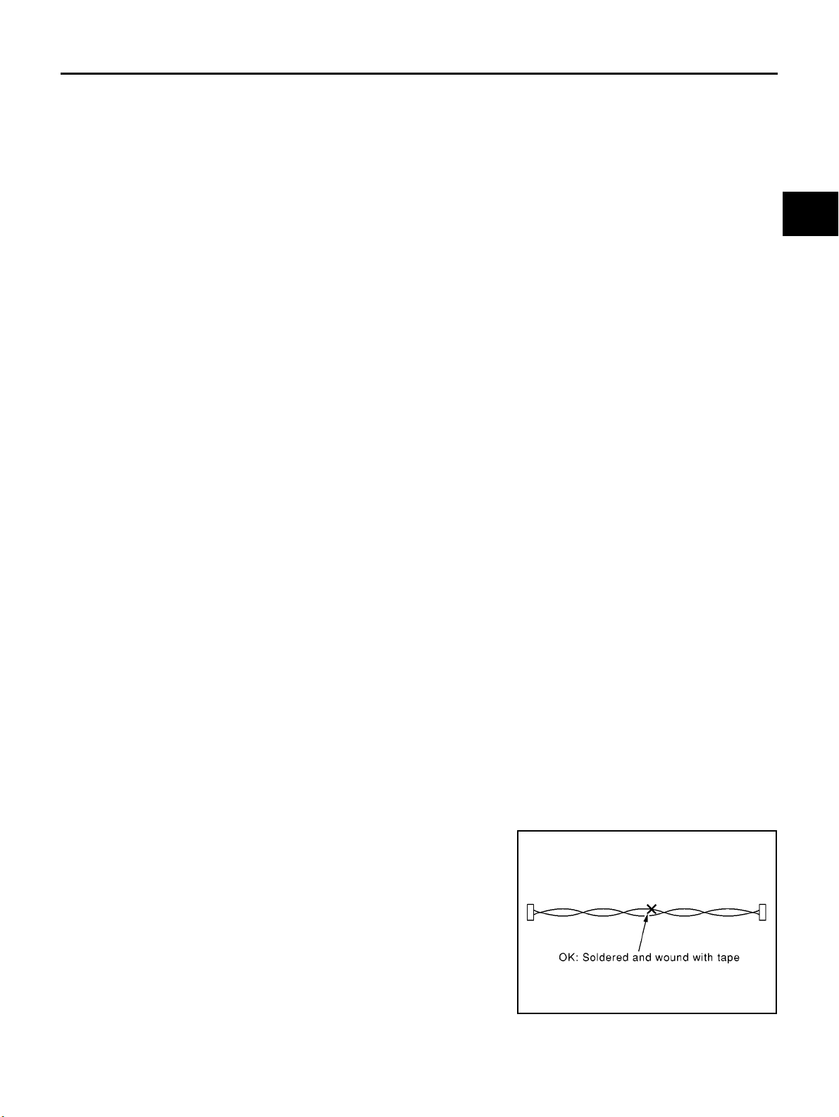
● Solder the repaired parts, and wrap with tape. [Frays of twisted
line must be within 110 mm (4.33 in)]
AT-5
ECS004VN
ECS004VO
PKIA0306E
L
M
Page 10
PRECAUTIONS
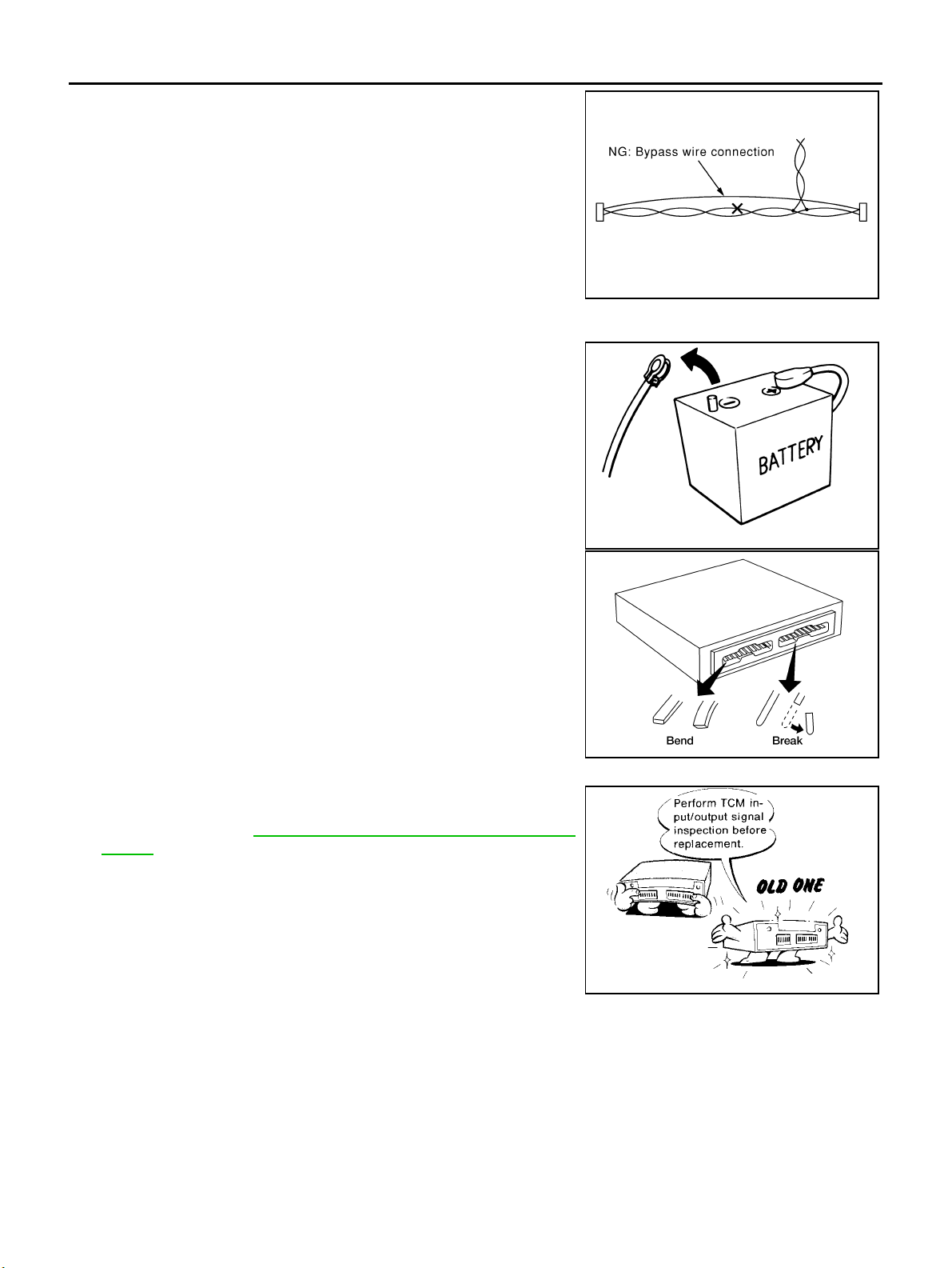
● Do not perform by pass wire connections for the repair
parts.(The spliced wire will become separated and the characteristics of twisted line will be lost.)
PKIA0307E
Precautions
● Before co nnecting or disconnecting the TCM harness con-
nector, turn ignition switch OFF and disconnect negative
battery terminal. Failure to do so may damage the TCM.
Because battery voltage is applied to TCM even if ignition
switch is turned off.
● When connecting or disconnecting pin connectors into or
from TCM, take care not to damage pin terminals (bend or
break).
Make sure that there are not any bends or breaks on TCM
pin terminal, when connecting pin connectors.
ECS004Q2
SEF289H
AAT470A
● Before replacing TCM, perform TCM input/output signal
inspection and make sure whether TCM functions properly
or not. (See page AT-12 5, "
TCM Terminals and Reference
Value".)
AT-6
MEF040DA
Page 11

PRECAUTIONS
● After performing each TROUBLE DIAGNOSIS, perform
“DTC (Diagnostic Trouble Code) CONFIRMATION PROCEDURE”.
The DTC should not be displayed in the “DTC CONFIRMATION PROCEDURE” if the repair is completed.
● Before proceeding with disassembly, thoroughly clean the out-
side of the transaxle. It is important to prevent the internal parts
from becoming contaminated by dirt or other foreign matter.
● Disassembly should be done in a clean work area.
● Use lint-free cloth or towels for wiping parts clean. Common
shop rags can leave fibers that could interfere with the operation
of the transaxle.
● Place disassemble d parts in order for easier and proper assembly.
● All parts should be carefully cleaned with a general purpose, non-flammable solvent before inspection or
reassembly.
● Gaskets, seals and O-rings should b e replaced any time the transaxle is disassembled.
● It is v ery important to perform functional tests whenever they are indicated.
● The valve body contains precision parts and requires extreme care when parts are removed and serviced.
Place disassembled val ve body parts in ord er for easier and proper assembly. Care will also prevent
springs and small parts from becoming scattered or lost.
● Properly installed valves, sleeves, plugs, etc. will slide along bores in valve body under their own weight.
● Before assembly, apply a coat of recommended ATF to all parts. Apply petroleum jelly to protect O-rings
and seals, or hold bearings and washers in pla ce during assembly. Do not use grease.
● Extreme care should be taken to avoid damage to O-rings, seals and gaskets when assembling.
● After overhaul, refill the transaxle with new ATF.
● When the A/T drain plug is removed, only some of the fluid is drained. Old A/T fluid will r em ain in torque
converter and ATF cooling system.
Always follow the procedures under “Changing A/T Fluid” in the AT section when chang ing A/T fluid. Refer
to “Changing A/T Fluid”, AT- 13, "
A/T FLUID" .
Service Notice or Precautions
FAIL-SAFE
The TCM has an electronic Fail-Safe (limp home mode). This allows the vehicle to be driven even if a major
electrical input/output device circuit is damaged.
Under Fail-Safe, the vehicle always runs in third gear, even with a shift lever position of “1”, “2” or “D”. The customer may complain of sluggish or poor acceleration.
When the ignition key is turned “ON” following Fail-Safe operation, O/D OFF indicator lamp blinks for about 8
seconds. Refer to SELF-DIAGNOSTIC PRO CED UR E(WITH OUT CONSULT-II)", AT-273, "
dure Without CONSULT-II" (EXCEPT FOR EURO-OBD) or "TCM Self-diagnostic Procedure(NO TOOLS)",
AT-51 , "
TCM SELF-DIAGNOSTIC PROCEDURE (NO TOOLS)" (EURO-OBD).
The blinking of the O/D OFF indicator lamp for about 8 seconds will appear only once and be cleared. The
customer may resume normal d riving conditions.
Always follow the “WORK FLOW”, refer to AT-284, "
Work Flow" (EXCEPT FOR Euro-OBD) or AT-61, "Work
Flow" (Euro-OBD).
The SELF-DIAGNOSIS results will be as follows:
● The first SELF-DIAGNOSIS will indicate damage to the vehicle speed sensor or the revolution sensor.
● During the next SELF-DIAGNOSIS, performed after checking the sensor, no damages will be indicated.
Diagnostic Proce-
SAT652J
ECS004Q3
A
B
AT
D
E
F
G
H
I
J
K
L
M
TORQUE CONVERTER SERVICE
The torque converter should be replaced under any of the following conditions:
● External leaks in the hub weld area.
● Converter hub is scored or damaged.
● Converter pilot is broken, damaged or fits poorly into crankshaft.
● Steel particles are found after flushing the cooler and cooler lines.
● Pump is damaged or steel particles are found in the converter.
AT-7
Page 12

PRECAUTIONS
● Vehi cle h a s TCC shudder and/or no TCC ap ply. R eplace only after all hydraulic and el ectrical diagn oses
have been made. (Conv erter clutch material may be glazed.)
● Converter is contaminated with engine coolant containing antifreeze.
● Internal failure of s tato r roller clutch.
● Heavy clutch debris due to overheating (blue converter).
● Steel particles or clutch lining material found in fluid filter or on magnet when no internal parts in unit are
worn or damaged — indicates that lining material came from converter.
The torque converter should not be replaced if:
● The fluid has an odor, is discolored, and there is no evidence of metal or clutch facing particles.
● The threads in one or more of the converter bolt holes are damaged.
● Transaxle failure did not display evidence of damaged or worn internal parts, steel particles or clutch plate
lining material in unit and inside the fluid filter.
● Vehi cle has been expos ed t o hig h mil eage (only). The exce ption may be where the torq ue conve rter
clutch dampener plate lining has seen excess wear by vehicles operated in heavy and/or constant traffic,
such as taxi, delivery or police use.
EURO-OBD SELF-DIAGNOSIS — EURO-OBD —
● A/T s elf-diagnosis is performed by the TCM in combination with the ECM. The results can be read through
the blinking pattern of the O/D O FF indicator lamp or the malfunction indicator lamp (MIL) . Refer to the
table on AT-42, "
diagnostic result.
● The self-diagnostic results indicated by the MIL are automatically stored in both the ECM and TCM mem-
ories.
Always perform the procedure “HOW TO ERASE DTC” on AT-39, "
plete the repair and avoid unnecessary blinking of the MIL.
● The following self-diagnostic items can be detected using ECM self-diagnostic results mode* only when
the O/D OFF indicator l amp does not indicate any malfunctions.
– PNP switch
– A/T 1st, 2nd, 3rd, or 4th gear function
*: For details of EURO-OBD, refer to AT-37 , "
● Certain systems and components, especially th ose related to EURO-OBD, may use a new style
slide-locking type harness connector.
For description and how to disconnect, refer to PG-70, "
SELF-DIAGNOSTIC RESULT TEST MODE" for the indicator used to display each self-
HOW TO ERASE DTC" to com-
ON BOARD DIAGNOSTIC SYSTEM DESCRIPTION" .
HARNESS CONNECTOR" .
Wiring Diagrams and Trouble Diagnosis
When you read wiring diagrams, refer to the following:
● GI-14, "How to Read Wiring Diagrams".
● PG-2, "POWER SUPPLY RO UTING".
When you perform trouble diagnosis, refer to the following:
● GI-11, "HOW TO FOLLOW TEST GROUPS IN TROUBLE DIAGNOSES".
● "", “HOW TO PERFORM EFFICIENT DIAGNOSIS FOR AN ELECTRICAL INCIDENT”
AT-8
ECS004Q4
Page 13
PREPARATION
PREPARATION PFP:00100
Special Service Tools
ECS004Q5
A
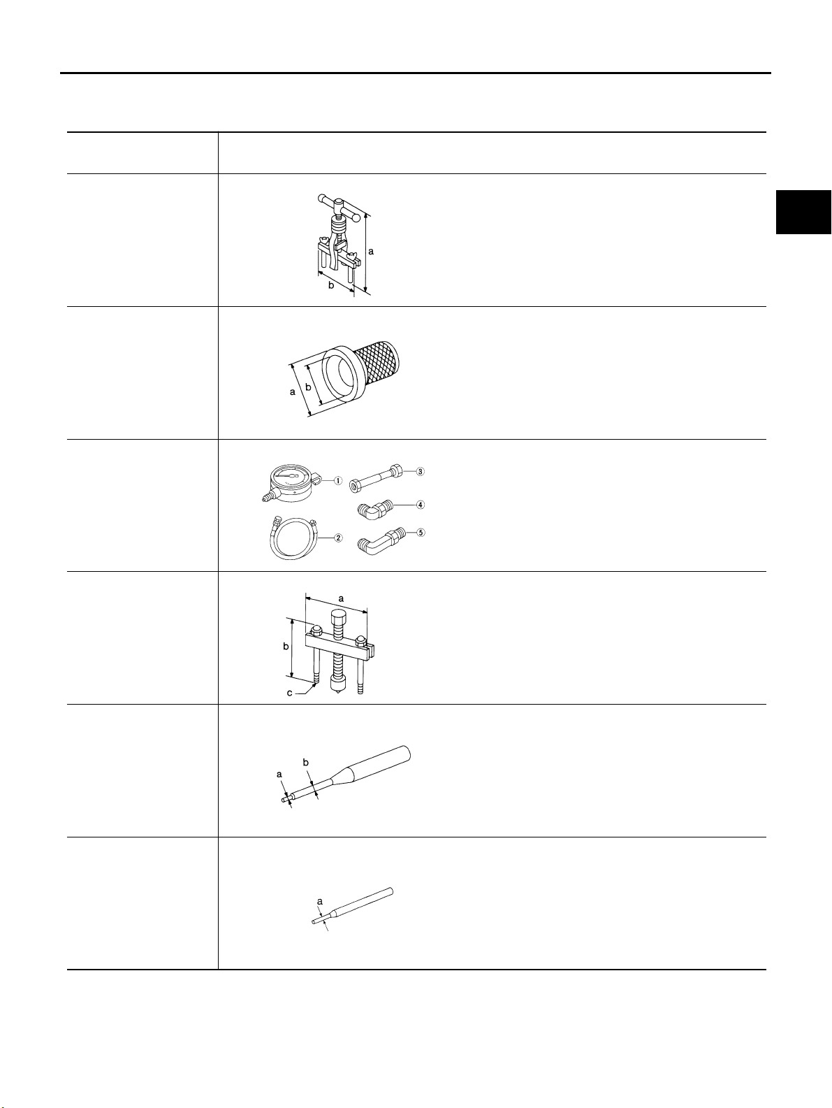
Tool nu m b e r
Tool na m e
KV381054S0 Puller
ST33400001 Drift
ST2505S001 Oil
pressure gauge set 1
ST25051001 Oil
pressure gauge 2
ST25052000 Hose 3
ST25053000 Joint pipe
4ST25054000Adapter
5ST25055000Adapter
Description
NT414
NT086
NT097
● Removing differential side oil seals
● Removing differential side bearing outer race
● Removing idler gear bearing outer race
a: 250 mm (9.84 in)
b: 160 mm (6.30 in)
● Installing differential side oil seal
F04B
● Installing oil seal on oil pump housing
a: 60 mm (2.36 in) dia.
b: 47 mm (1.85 in) dia.
● Measuring line pressure
B
AT
D
E
F
G
H
I
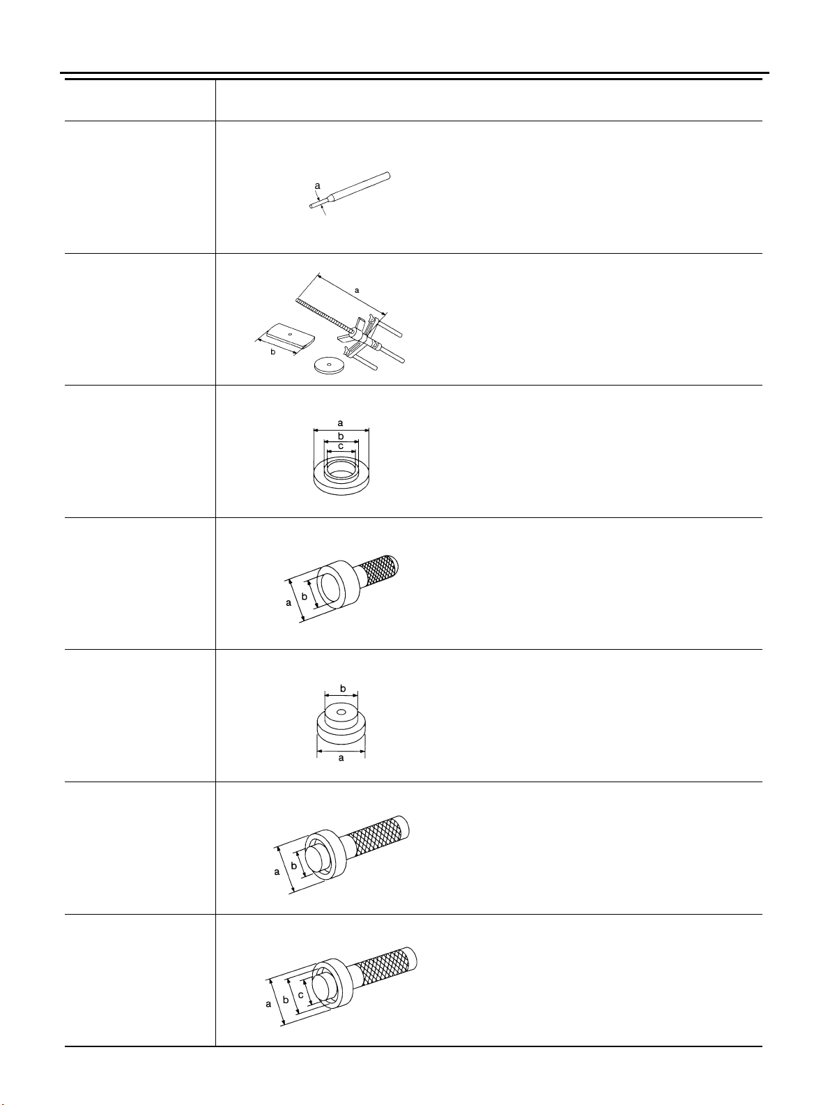
ST27180001 Puller
ST23540000 Pin punch
ST25710000 Pin punch
NT424
NT442
NT410
● Removing idler gear
a: 100 mm (3.94 in)
b: 110 m m (4.33 in)
c: M8 x 1.25P
● Removing and installing parking rod plate and
manual plate pins
a: 2.3 mm (0.091 in) dia.
b: 4 mm (0.16 in) dia.
● Aligning groove of manual shaft and hole of
transmission case
a: 2 mm (0.08 in) dia.
J
K
L
M
AT-9
Page 14
PREPARATION
To o l n um be r
To o l n am e
KV32101000 Pin
punch
KV31102400 Clutch
spring compres-sor
KV40100630 Drift
Description
● Removing and installing manual shaft retaining
pin
● Removing and installing pinion mate shaft lock
pin
a: 4 mm (0.16 in) dia.
NT410
● Removing and installing clutch return springs
● Installing low and reverse brake piston
a: 320 mm (12.60 in)
b: 174 mm (6.85 in)
NT423
● Installing reduction gear bearing inner race
● Installing idler gear bearing inner race
a: 67.5 mm (2.657 in) dia.
b: 44 mm (1.73 in) dia.
c: 38.5 mm (1.516 in) dia.
ST30720000 Bearing
installer
ST35321000 Drift
ST33230000 Drift
ST33220000 Drift
NT107
● Installing idler gear bearing outer race
a: 77 mm (3.03 in) dia.
b: 55.5 mm (2.185 in) dia.
NT115
● Installing output shaft bearing
a: 49 mm (1.93 in) dia.
b: 41 mm (1.61 in) dia.
NT073
● Installing differential side bearing inner race
a: 51 mm (2.01 in) dia.
b: 28.5 mm (1.122 in) dia.
NT084
● Selecting differential side bearing adjusting shim
a: 37 mm (1.46 in) dia.
b: 31 mm (1.22 in) dia.
c: 22 mm (0.87 in) dia.
NT085
AT-10
Page 15
PREPARATION
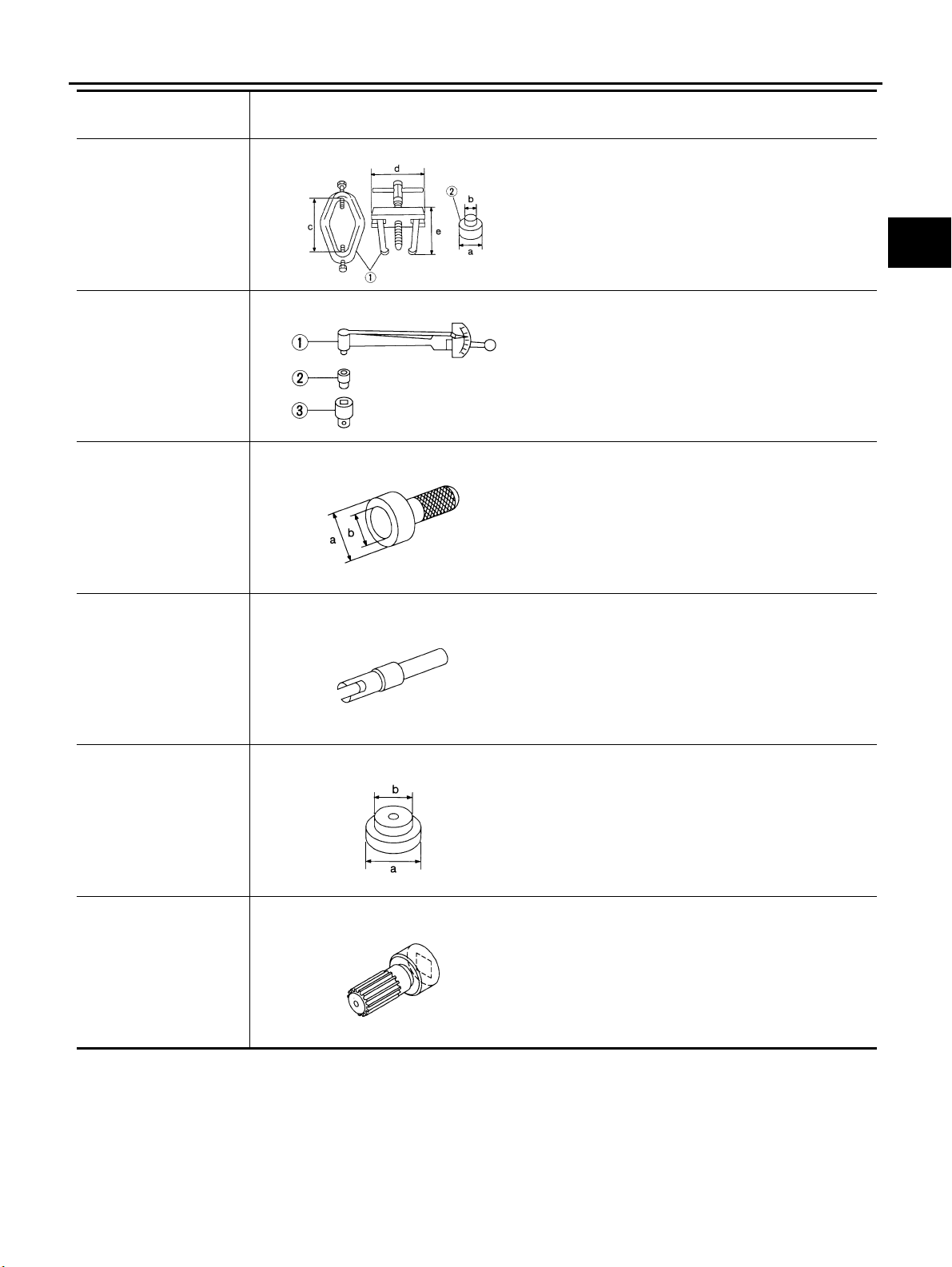
Tool nu m b e r
Tool na m e
ST3306S001
Differential side
bearing puller set 1
ST33051001 Puller 2
ST33061000 Adapter
ST3127S000 Preload
gauge 1 GG91030000
Torque w r e n c h 2
HT62940000 Socket
adapter 3 HT62900000
Socket adapter
ST35271000 Drift
Description
AMT153
NT124
NT115
● Removing differential side bearing inner race
a: 38 mm (1.50 in) dia.
b: 28.5 mm (1.122 in) dia.
c: 130 mm (5.12 in)
d: 135 mm (5.31 in)
e: 100 mm (3.94 in)
● Checking differential side bearing preload
● Installing idler gear
● Installing differential side bearing inner race
a: 72 mm (2.83 in) dia.
b: 63 mm (2.48 in) dia.
A
B
AT
D
E
F
G
H
KV38107700 Preload
adapter
ST30613000 Drift
KV38105210 Preload
adapter
NT087
NT073
NT075
● Selecting differential side bearing adjusting shim
● Checking differential side bearing preload
● Installing differential side bearing inner race
a: 72 mm (2.83 in) dia.
b: 48 mm (1.89 in) dia.
● Selecting differential side bearing adjusting shim
● Checking differential side bearing preload
I
J
K
L
M
Commercial Service Tools
ECS004Q6
AT-11
Page 16
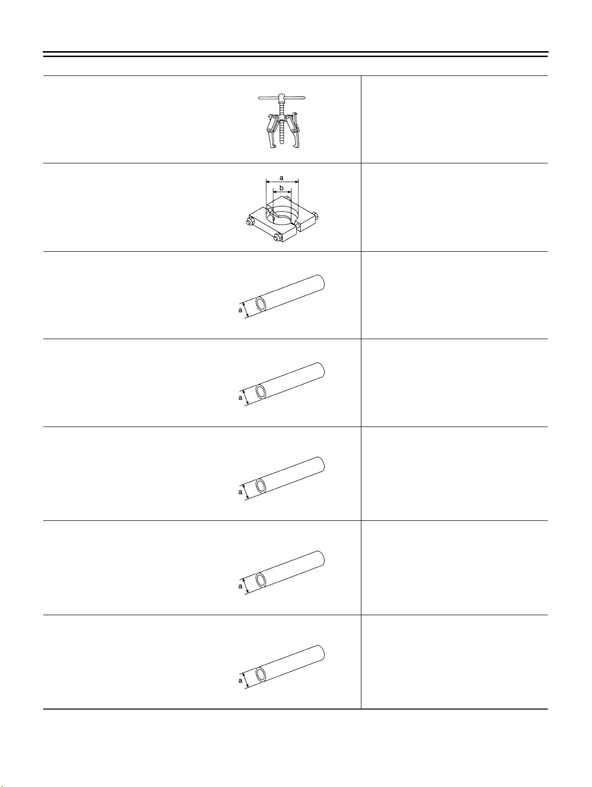
To o l n am e D e s c ri pt io n
PREPARATION
Puller
Puller
Drift
Drift
● Removing idler gear bearing inner race
● Removing and installing band servo piston
snap ring
NT077
● Removing reduction gear bearing inner
race
a: 60 mm (2.36 in) dia.
b: 35 mm (1.38 in) dia.
NT411
● Installing differential side oil seal
a: 90 mm (3.54 in) dia.
NT083
● Installing needle bearing on bearing
retainer
a: 36 mm (1.42 in) dia.
Drift
Drift
Drift
NT083
● Removing needle bearing from bearing
retainer
a: 33.5 mm (1.319 in) dia.
NT083
● Installing differential side bearing outer
race
a: 75 mm (2.95 in) dia.
NT083
● Installing differential side bearing outer
race
a: 100 mm (3.94 in) dia.
NT083
AT-12
Page 17
A/T FLUID
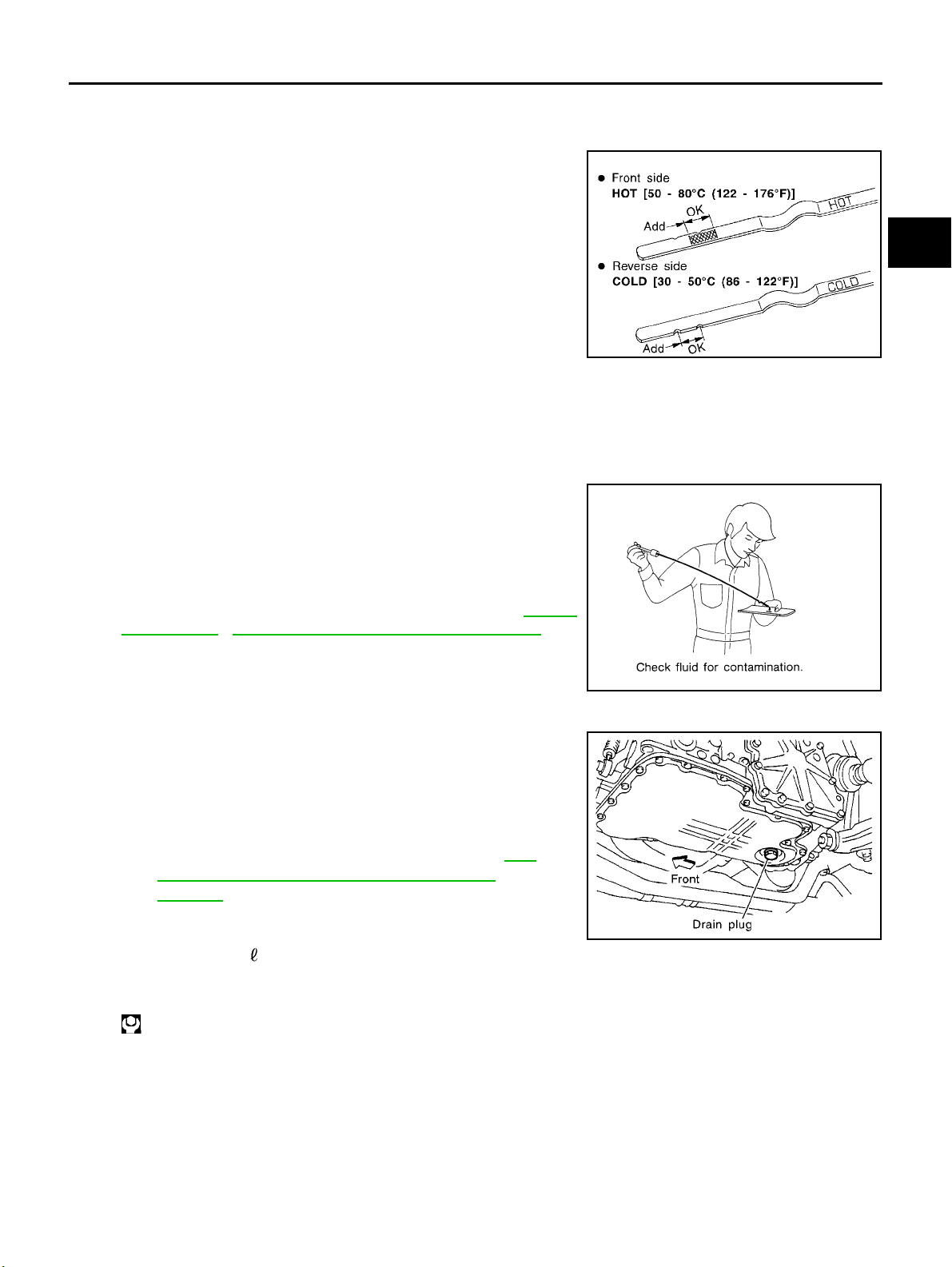
A/T FLUID PFP:KLE40
Checking A/T Fluid
1. Warm up engine.
2. Check for fluid leakage.
3. Before driving, fluid level can be checked at fluid temperatures
of 30 to 50°C(86to122°F) u sing “COLD” range on dipstick.
a. Park vehicle on level surface and set parking brake.
b. Start engine and move selector lever through each gear posi-
tion. Leave selector lev er in “P” position.
c. C heck fluid level with engine idling.
d. Remove dipstick and note reading. If level is at low side of either
range, and fluid to the charging pipe.
e. Re-insert dipstick into charging pipe as far as it will go.
f. Remove dipstick and note reading. If reading is at low side of range, add fluid to the charging pipe.
Do not overfill.
4. Drive vehicle for approximately 5 minutes in urban areas.
5. Re-check fluid level at fluid temperatures of 50 to 80°C(122to176°F) using “HOT” range on dipstick.
6. Check fluid condition.
● If fluid is very dark or smells burned, refer to AT section for
checking operation of A/T. Flush cooling system after repair of
A/T.
● If A/T fluid c ontains frictional material (clutches, bands, etc.),
replace radiator and flush cooler line using cleaning solvent
and compressed air after repair of A/T. Refer to CO-12,
"RADIATOR" , CO-15, "RADIATOR (ALUMINUM TYPE)" ,,.
ECS004Q7
SMA827CA
A
B
AT
D
E
F
G
H
I
SMA853B
Changing A/T Fluid
ECS004Q8
1. Warm up A/T fluid.
2. Stop engine.
3. Drain A/T fluid from drain plug and refill with new A/T fluid.
Always refill sa me volume with drained fluid.
Fluid grade:
Genuine Nissan ATF or equivalent. Refer to MA-
17, "RECOMMENDED FLUIDS AND LUBRICANTS" .
Fluid capacity (With torque converter):
SMA027D
Approx. 8.0 (7.01 lmp qt)
Drain plug:
:29-39N·m(3.0-4.0kg-m,22-29ft-lb)
4. Run engine at idle speed for five minutes.
5. Check fluid level and condition. Refer to “Checking A/T Fluid”. If fluid is still dirty, repeat steps 2 through 5.
J
K
L
M
AT-13
Page 18

OVERALL SYSTEM
OVERALL SYSTEM
A/T Electrical Parts Location
PFP:00000
ECS004Q9
AT-14
Page 19
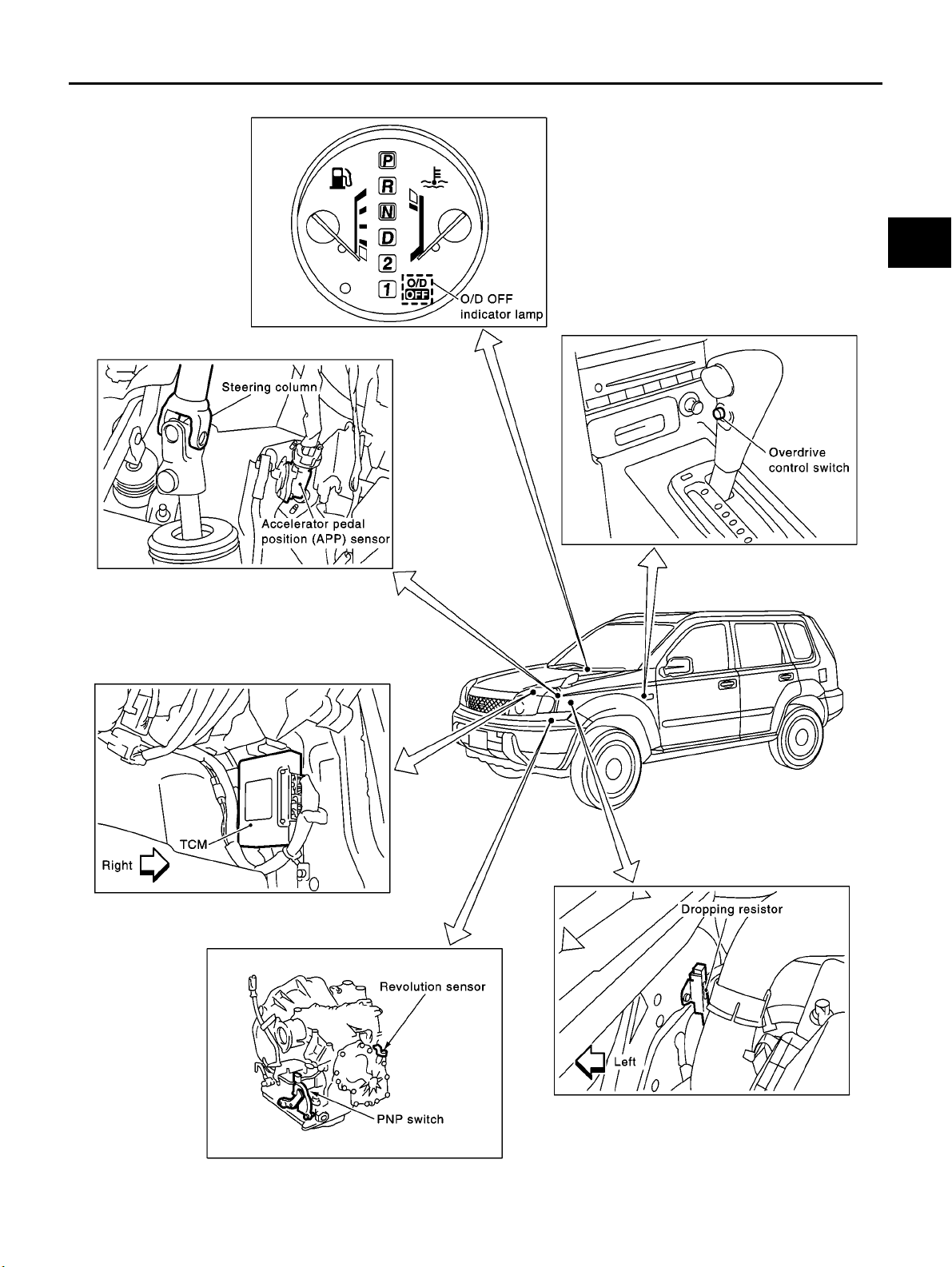
OVERALL SYSTEM
A
B
AT
D
E
F
G
H
K
M
I
J
L
AT-15
SCIA0687E
Page 20
OVERALL SYSTEM
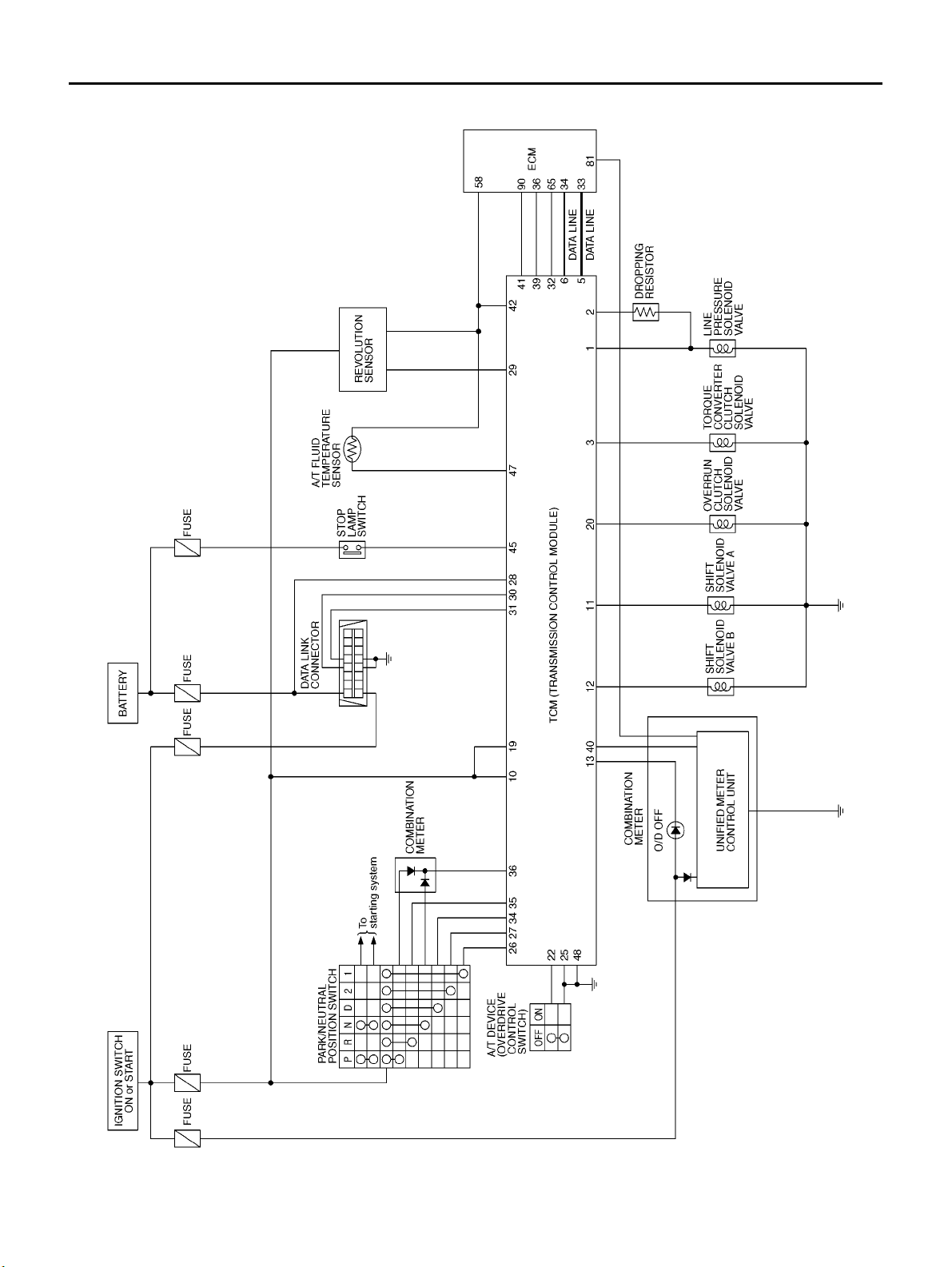
Circuit Diagram
ECS004QA
AT-16
TCWA0035E
Page 21
OVERALL SYSTEM
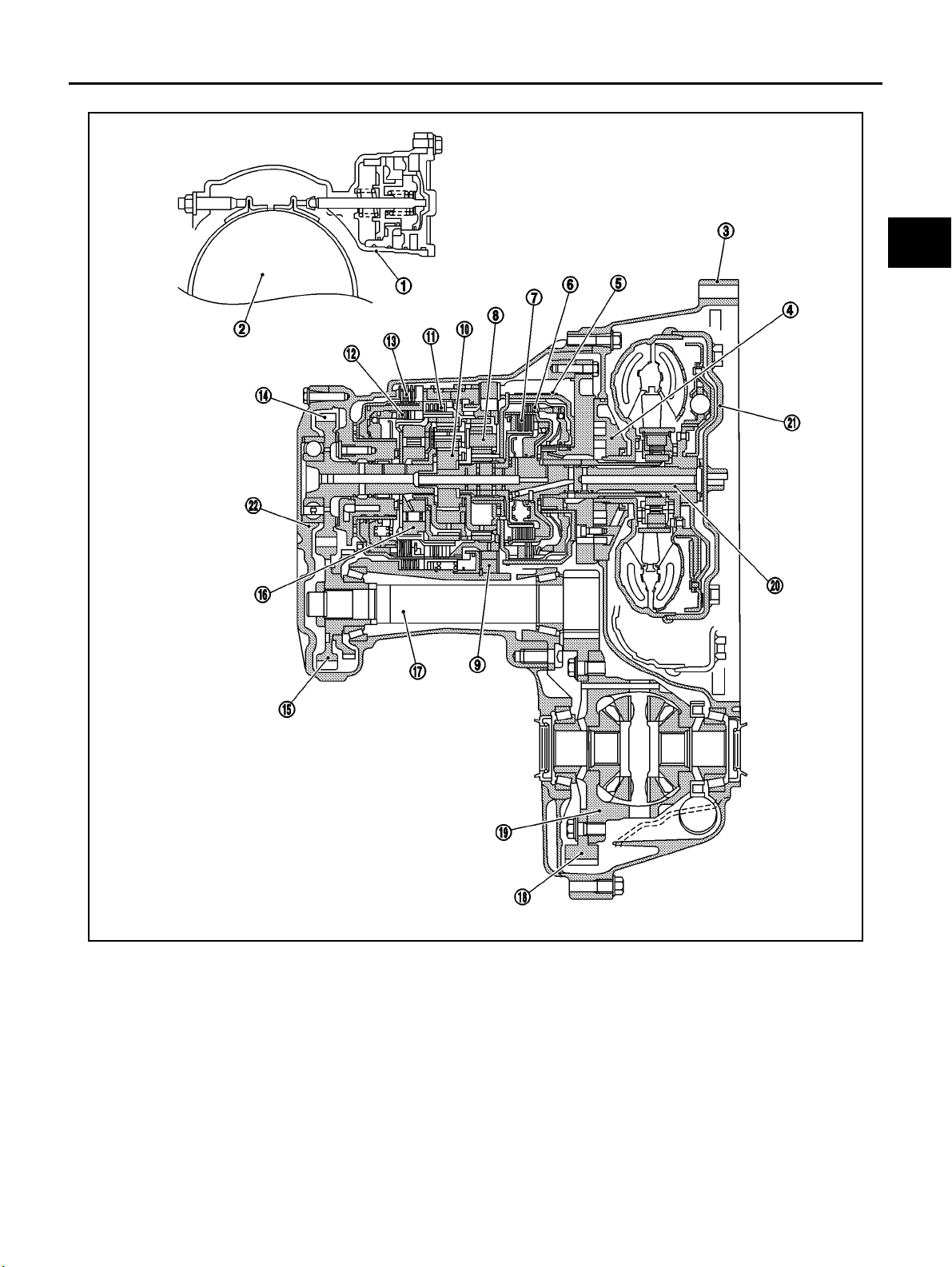
Cross-sectional View
ECS004QB
A
B
AT
D
E
F
G
H
1. Band servo piston 9. Low one-way clutch 17. Pinion reduction gear
2. Reverse clutch drum 10. Rear planetary gear 18. Final gear
3. Converter housing 11. Forward clutch 19. Differential case
4. Oil pump 12. Overrun clutch 20. Input shaft
5. Brake band 13. Low & reverse brake 21. Torque converter
6. Reverse clutch 14. Output gear 22. Side cover
7. High clutch 15. Idler gear
8. Front planetary gear 16. Forward one-way clutch
I
J
K
L
M
SCIA0688E
AT-17
Page 22
OVERALL SYSTEM
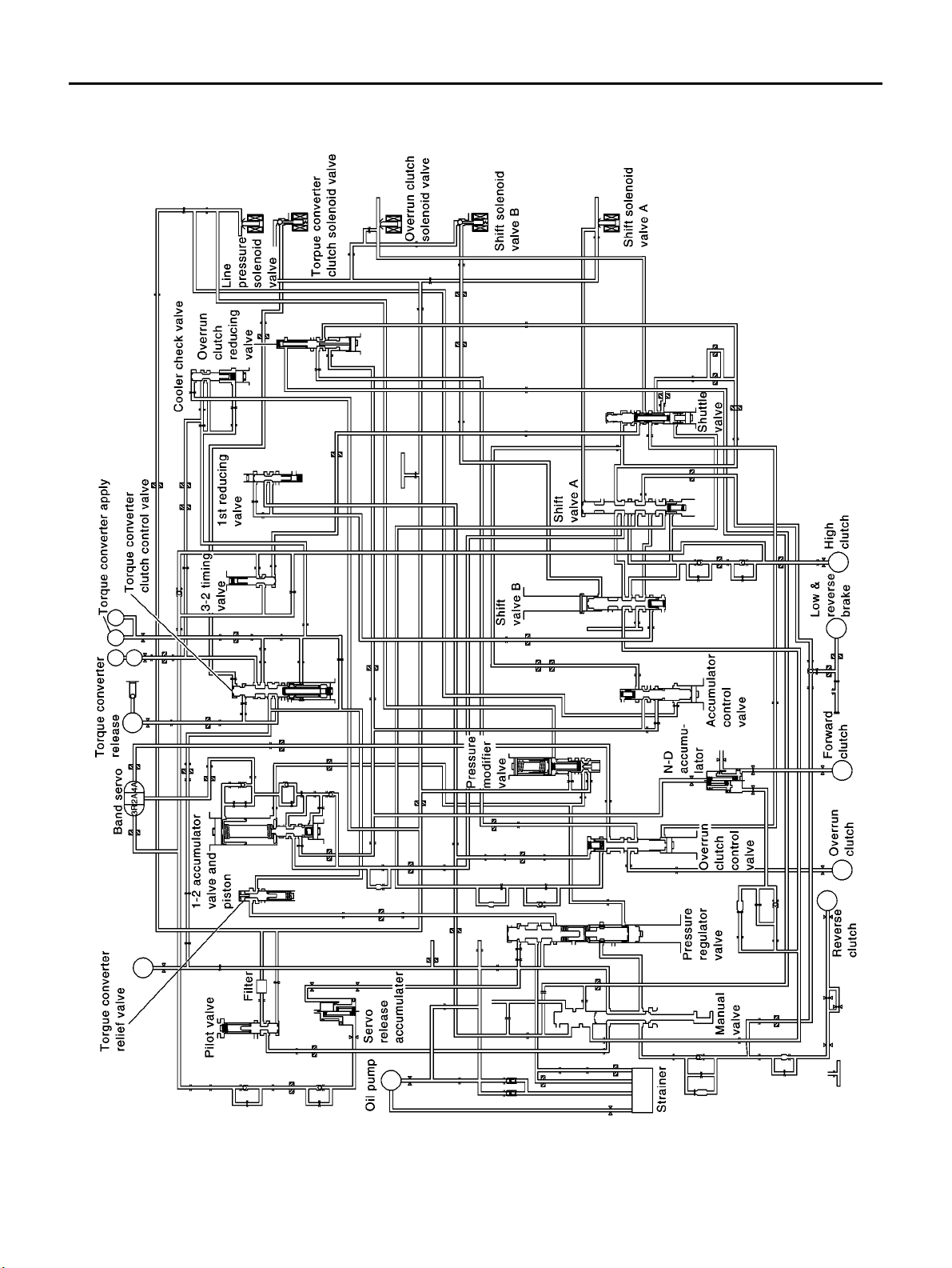
Hydraulic Control Circuit
ECS004QC
AT-18
SCIA0689E
Page 23
OVERALL SYSTEM
Shift Mechanism
CONSTRUCTION
SAT998I
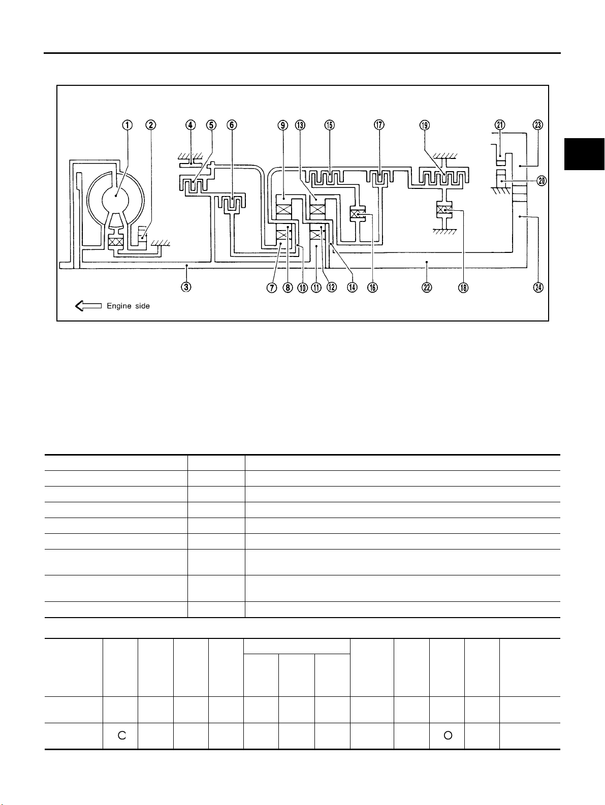
1. T orque converter 2. Oil pump 3. Input shaft
4. Brake band 5. Reverse clutch 6. High clutch
7. Front sun gear 8. Front pinion gear 9. Front internal gear
10. Front planetary carrier 11. Rear sun gear 12. Rear pinion gear
13. Rear internal gear 14. Rear planetary carrier 15. Forward clutch
16. Forward one-way clutch 17. Overrun clutch 18. Low one-way clutch
19. Low & reverse brake 20. Parking pawl 21. Parking gear
22. Output shaft 23. Idle gear 24. Output gear
FUNCTION OF CLUTCH A ND BRAK E
Clutch and brake components Abbr. Function
5 Reverse clutch R/C To transmit input power to front sun gear 7 .
6 High clutch H/C To transmit input power to front planetary carrier 10 .
15 Forward clutch F/C T o connect front planetary carrier 10 with forward one-way clutch 16 .
17 Overrun clutch O/C T o connect front planetary carrier 10 with rear internal gear 13 .
4 Brake band B/B To lock front sun gear 7 .
16 Forward one-way clutch F/O.C When forward clutch 15 is engaged, to stop rear internal gear 13 from rotating in
opposite direction against engine revolution.
18 Low one-way clutch L/O.C T o stop front planetary carrier 10 from rotating in opposite direction against
engine revolution.
19 Low & reverse brake L & R/B T o lock front planetary carrier 10 .
ECS004QD
A
B
AT
D
E
F
G
H
I
J
K
L
M
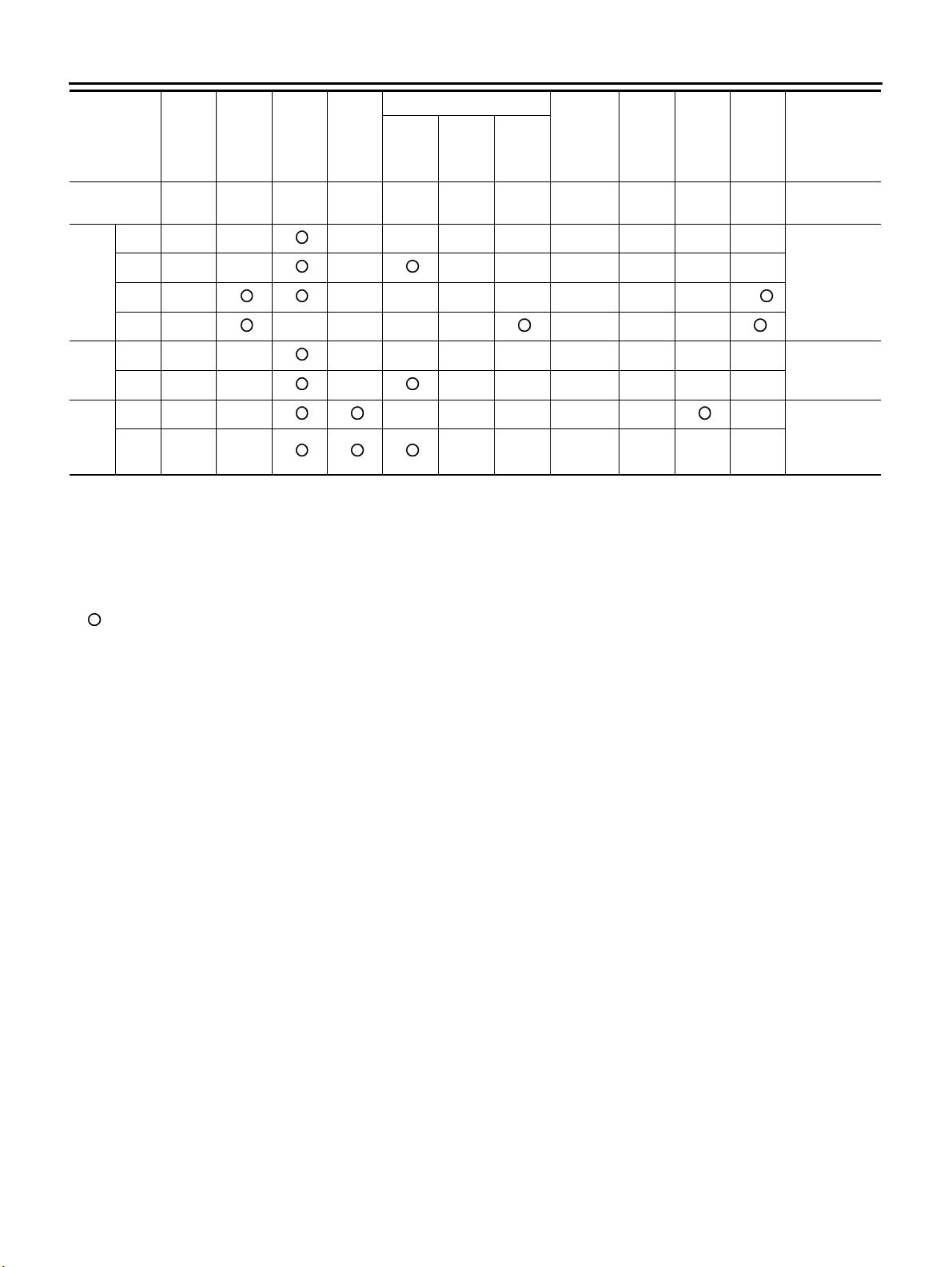
CLUTCH AND BAND CHART
For-
ward
clutch
6
15
Shift position
P
R
Rever
se
clutch
5
High
clutch
Over-
run
clutch
17
2nd
apply
Band servo
3rd
releas
e
AT-19
4th
apply
Forward
one-way
clutch
16
Low
one-
way
clutch
18
Low &
revers
e
brake
19
Lock-
up
Remarks
PARK
POSITION
REVERSE
POSITION
Page 24
OVERALL SYSTEM
18
Low &
revers
e
brake
19
Lock-
up
Remarks
NEUTRAL
POSITION
Shift position
N
Rever
se
clutch
5
High
clutch
6
For-
ward
clutch
15
Over-
run
clutch
17
2nd
apply
Band servo
3rd
releas
e
4th
apply
Forward
one-way
clutch
16
Low
one-
way
clutch
1st *1D B B
2nd *1A B
D*4
3rd *1A *2C C B
*5
Automatic
shift
1 ⇔ 2 ⇔ 3 ⇔
4
4th C *3C C
1st D B B
2
2nd A B
1st B
1
2nd B
● *1: Operates when overdrive control switch is set in “OFF” position.
● *2: Oil pressure is applied to both 2nd “apply” side and 3rd “release” side of band servo piston. However, brake band does not con-
Automatic
shift
1 ⇔ 2
Locks (held
stationary) in
1st speed
1 ⇐ 2
tract because oil pressure area on the “release” side is greater than that on the “apply” side.
● *3: Oil pressure is applied to 4th “apply” side in condition *2 above, and brake band contracts.
● *4: A/T will not shift to 4th when overdrive control switch is set in “OFF” position.
● *5: Operates when overdrive control switch is “OFF”.
● :Operates.
● A: Operates when throttle opening is less than 3/16, activating engine brake.
● B: Operates during “progressive” acceleration.
● C: Operates but does not affect power transmission.
● D: Operates when throttle opening is less than 3/16, but does not affect engine brake.
POWER TRANSMISSION
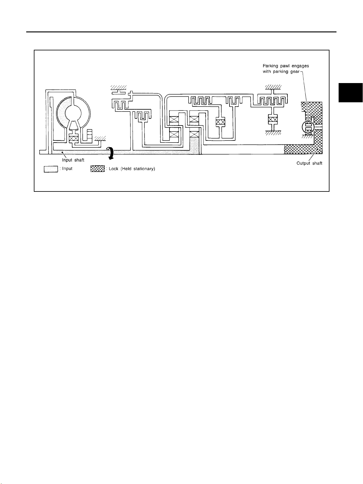
“N” and “P” Positions
● “N” position
Power from the input shaft is not transm itted to the output shaft because the clutches do not operate.
● “P” position
AT-20
Page 25
OVERALL SYSTEM
Similar to the “N” position, the clutches do not operate. The parking pawl engages with the parking gear to
mechanically hold the output shaft so that the power train is locked.
A
B
AT
D
E
F
SAT991I
G
H
I
J
K
L
M
AT-21
Page 26
OVERALL SYSTEM
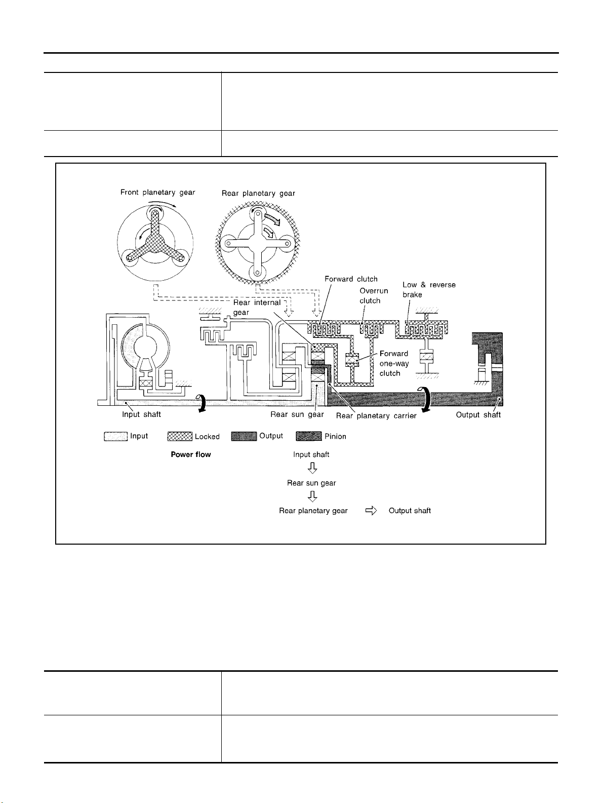
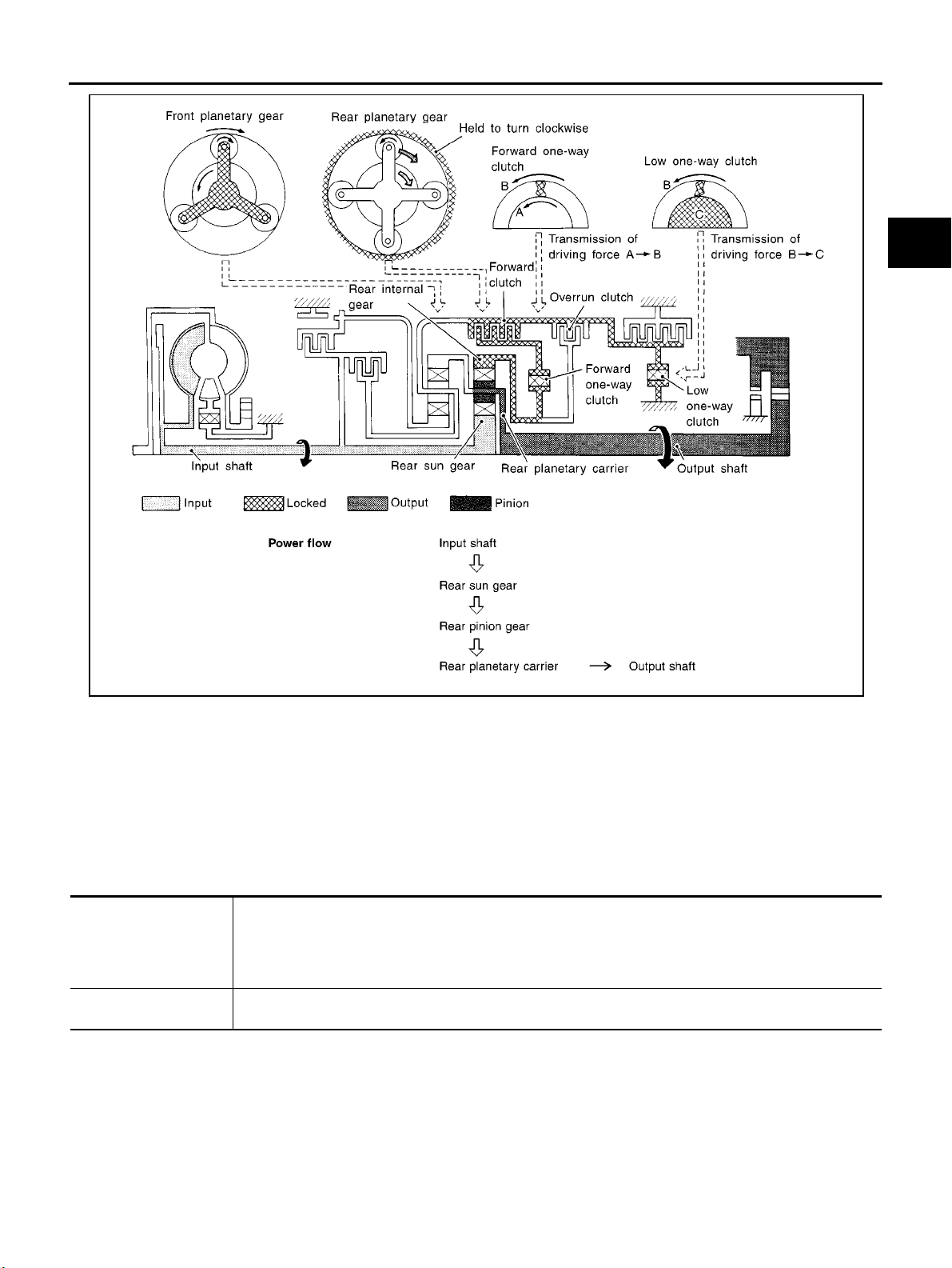
“11 ”Position
● Forward clutch
● Forward one-way clutch
● Overrun clutch
● Low and reverse brake
Engine brake Overrun clutch always engages, therefore engine brake can be obtained when deceler-
As overrun clutch engages, rear internal gear is locked by the operation of low and
reverse brake.
This is different from that of D
1 and 21 .
ating.
1 ”and“21 ”Positions
“D
● Forward one-way clutch
● Forward clutch
● Low one-way clutch
Overrun clutch
engagement conditions
(Engine brake)
SAT374J
Rear internal gear is locked to rotate counterclockwise because of the functioning of
these three clutches.
D
1 :Overdrivecontrolswitch“OFF”andthrottleopeningislessthan3/16
2
1 :Alwaysengaged
At D
1 and 21 positions, engine brake is not activated due to free turning of low one-
way clutch.
AT-22
Page 27
OVERALL SYSTEM
A
B
AT
D
E
F
G
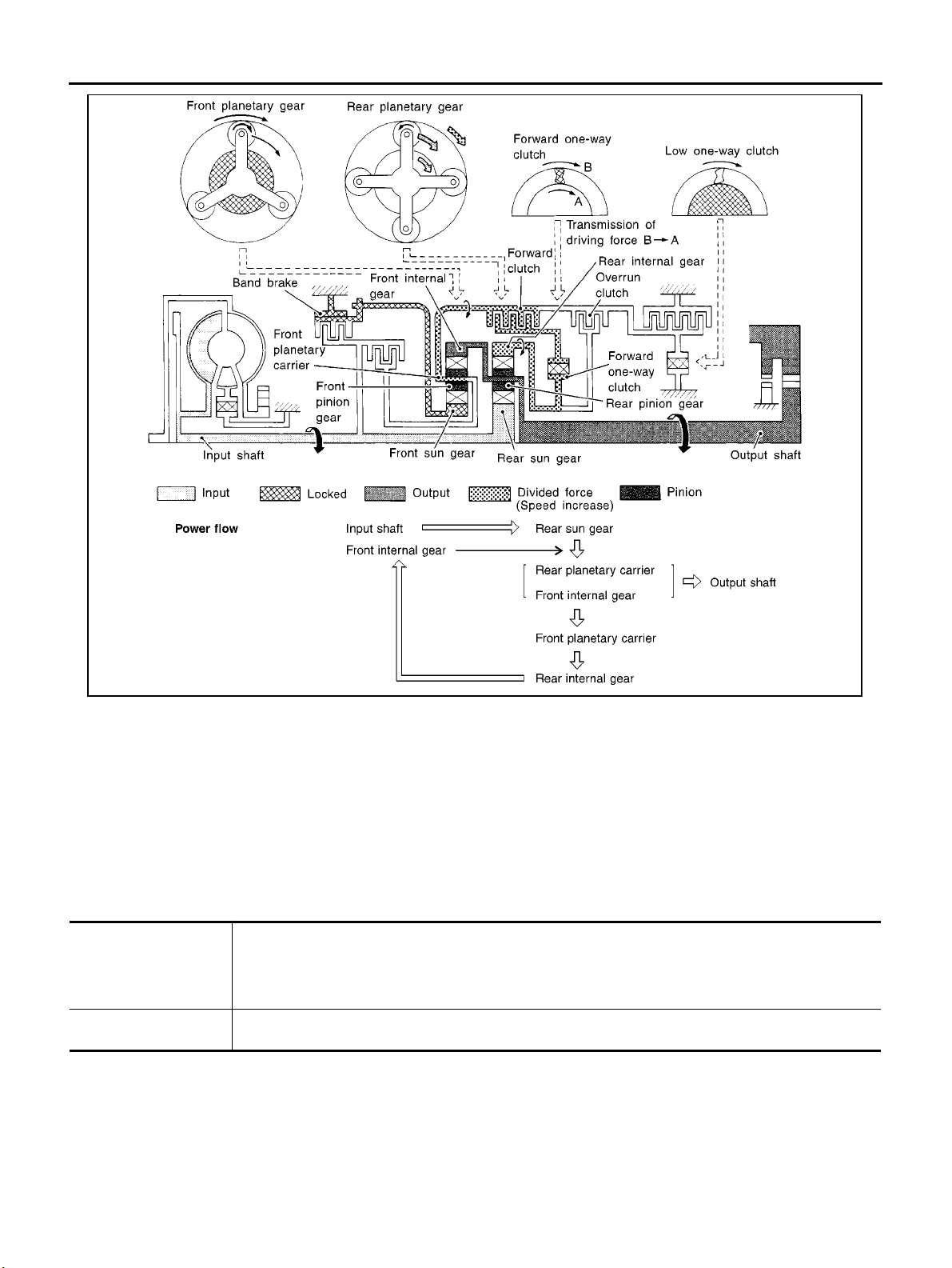
“D2 ”, “2 2 ”and“12 ”Positions
● Forward clutch
● Forward one-way
clutch
● Brake band
Overrun clutch
engagement conditions
Rear sun gear drives rear planetary carrier and combined front internal gear. Front internal gear now
rotates around front sun gear accompanying front planetary carrier.
As front planetary carrier transfers the power to rear internal gear through forward clutch and forward oneway clutch, this rotation of rear internal gear increases the speed of rear planetary carrier compared with
that of the 1st speed.
D
2 :Overdrivecontrolswitch“OFF”andthrottleopeningislessthan3/16
2 and 12 :Alwaysengaged
2
SAT377J
H
I
J
K
L
M
AT-23
Page 28
OVERALL SYSTEM
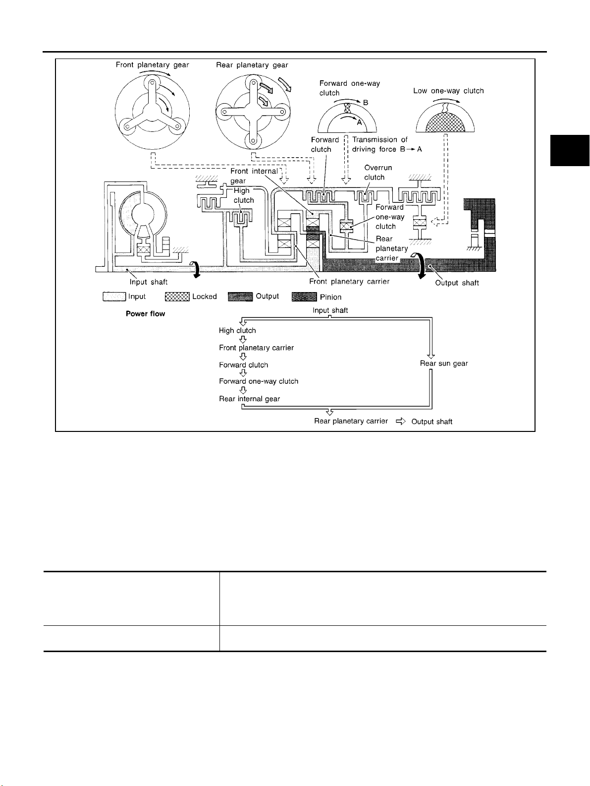
“D3 ”Position
● High clutch
● Forward clutch
● Forward one-way
clutch
Overrun clutch
engagement conditions
SAT378J
Input power is transmitted to front planetary carrier through high clutch. And front planetary carrier is connected to rear internal gear by operation of forward clutch and forward one-way clutch.
This rear internal gear rotation and another input (the rear sun gear) accompany rear planetary carrier to
turn at the same speed.
3 :Overdrivecontrolswitch“OFF”andthrottleopeningislessthan3/16
D
AT-24
Page 29
OVERALL SYSTEM
A
B
AT
D
E
F
G
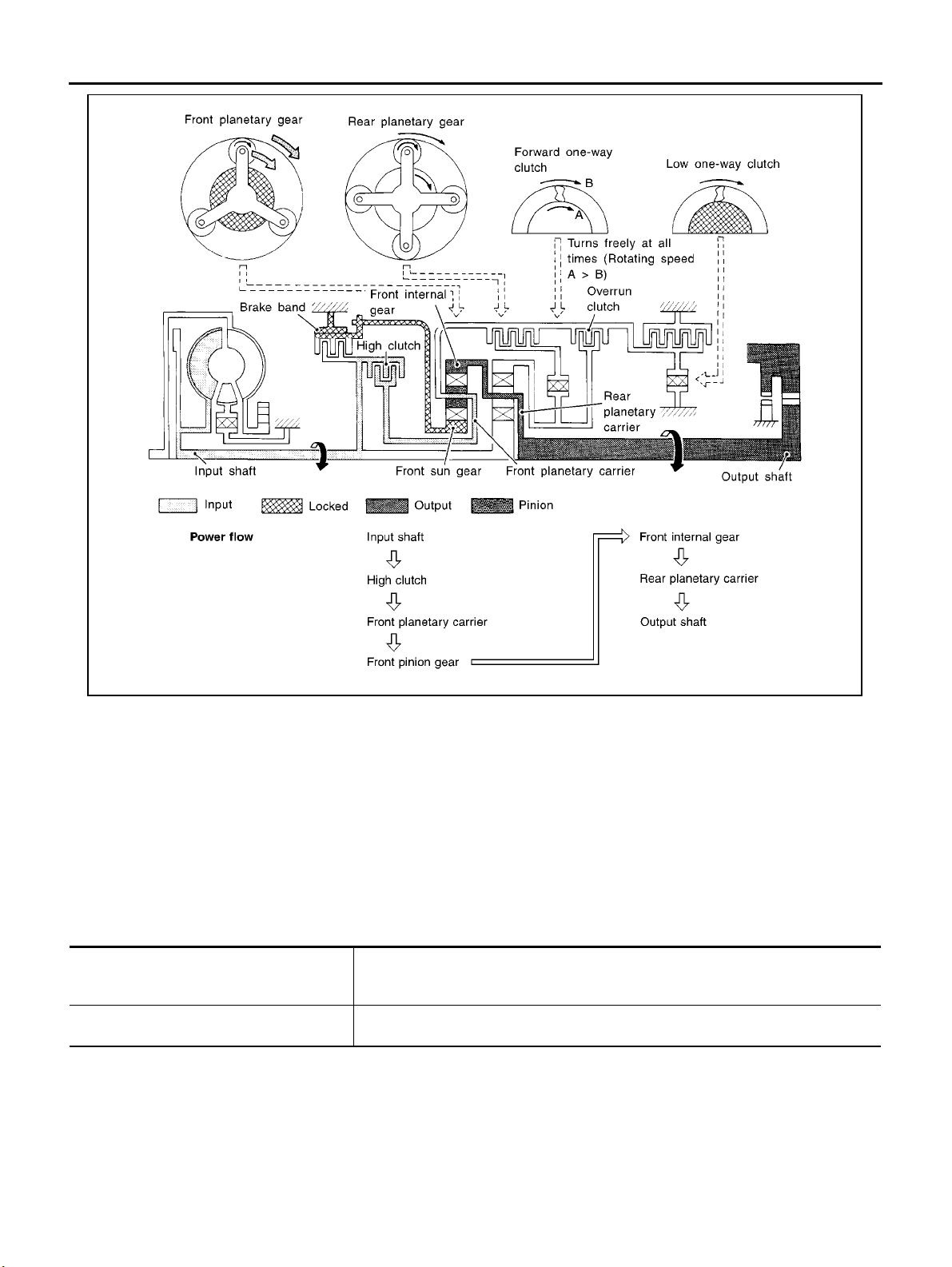
“D4 ”(OD)Position
● High clutch
● Brake band
● Forward clutch (Does not affect power
transmission)
Engine brake
SAT379J
Input power is transmitted to front carrier through high clutch.
This front carrier turns around the sun gear which is fixed by brake band and makes
front internal gear (output) turn faster.
4 position, there is no one-way clutch in the power transmission line and engine
At D
brake can be obtained w hen decelerating.
H
I
J
K
L
M
AT-25
Page 30
OVERALL SYSTEM
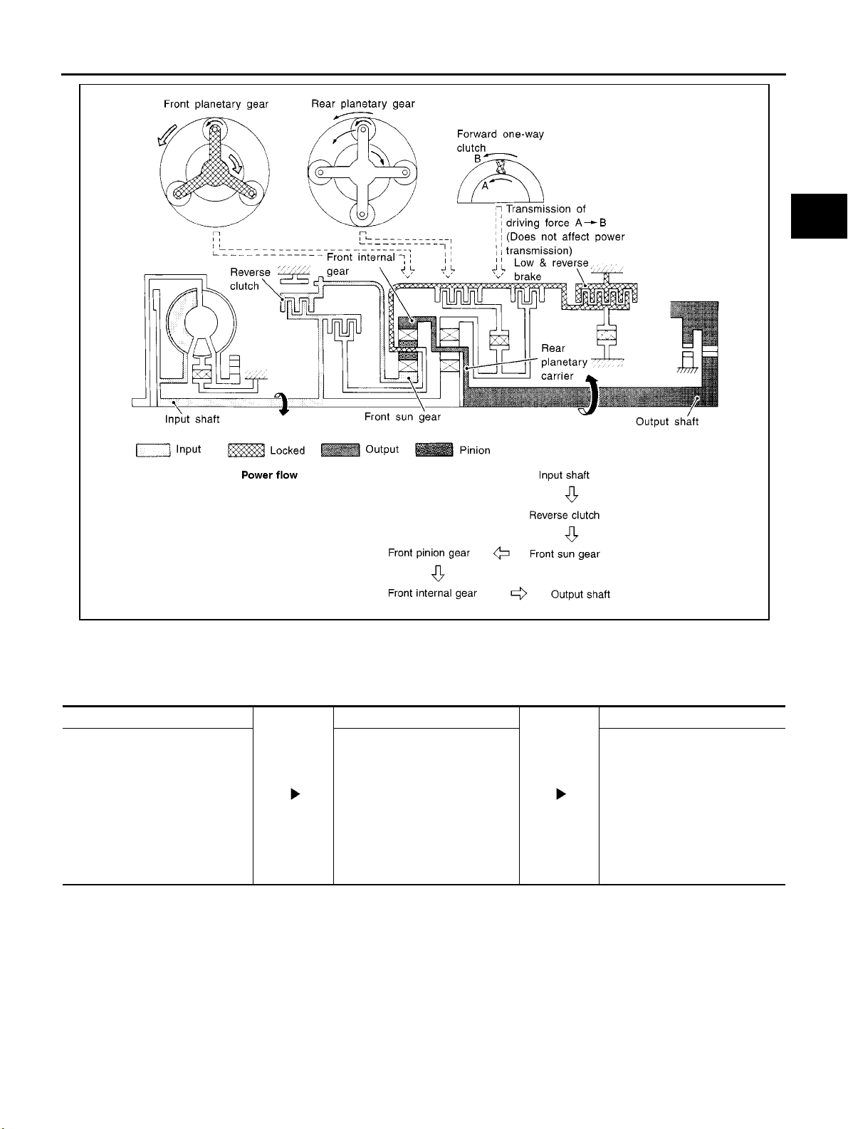
“R” Position
● Reverse clutch
● Low and reverse brake
Engine brake
SAT380J
Front planetary carrier is stationary because of the operation of low and reverse brake.
Input power is transmitted to front sun gear through reverse clutch, which drives front
internal gear in the opposite direction.
As there is no one-way clutch in the power transmission line, engine brake can be
obtained when decelerating.
AT-26
Page 31
OVERALL SYSTEM
A
B
AT
D
E
F
G
SAT381J
Control System
ECS004QE
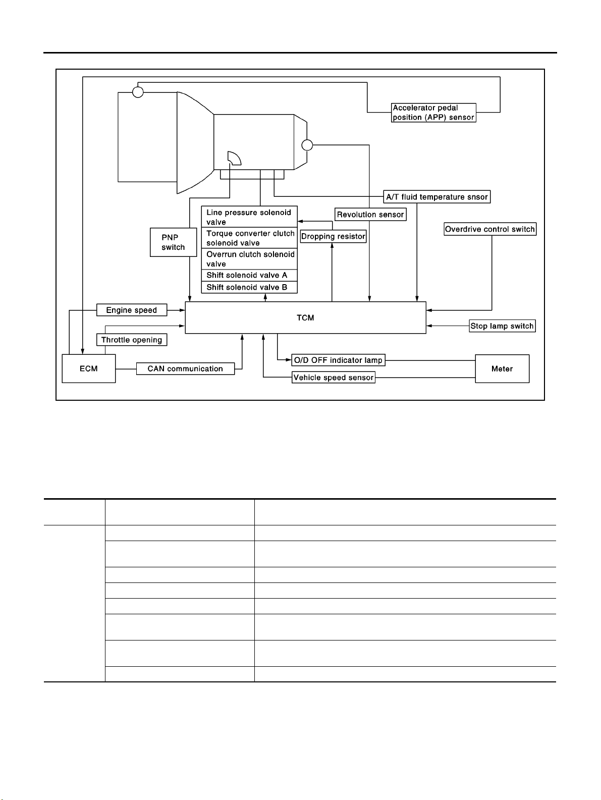
OUTLINE
The a utomatic transaxle senses vehicle operating conditions through various switches and sensors. It always
controls the optimum shift position and reduces shifting and lock-up shocks.
SWITCHES & SENSORS TCM ACTUATORS
PNP switch
Throttle position sensor*
Engine speed signal
A/T fluid temperature sensor
Revolution sensor
Vehicle sp eed sensor
Overdrive control switch
Stop lamp switch
*: This sensor means Accelerator pedal position (APP) sensor.
Shift control
Line pressure control
Lock-up control
Overrun clutch control
Timing control
Fail-safe control
Self-diagnosis
CONSULT-II communication line
control
Shift solenoid valve A
Shift solenoid valve B
Overrun clutch solenoid valve
To r q u e c o n ve rt er cl u t ch so l e n oid
valve
Line pressure solenoid valve
O/D OFF indicator lamp
H
I
J
K
L
M
AT-27
Page 32
CONTROL SYSTEM
OVERALL SYSTEM
TCM FUNCTION
The function of the TCM is to:
● Receive input signals sent from various switches and sensors.
● Determine required line pressure, shifting point, l ock-up operation, and eng ine brake operation.
● Send required output signals to the respective solenoids.
INPUT/OUTPUT SIGNAL OF TCM
Input
Sensors, switches and solenoid
valves
PNP switch Detects select lever position and sends a signal to TCM.
Throttle position sensor (accelerator
pedal position(app) sensor
Engine speed signal From ECM.
A/T fluid temperature sensor Detects transmission fluid temperature and sends a signal to TCM.
Revolution sensor Detects output shaft rpm and sends a signal to TCM.
Vehi cl e sp eed sensor
Overdrive control switch*1
Stop lamp switch Releases loc k-up system when depressing peda l in lock-up cond ition.
Detects throttle valve position and sends a signal to TCM.
Used as an auxiliary vehicle speed sensor. Sends a signal when revolution
sensor (installed on transmission) malfunctions.
Sends a signal, which prohibits a shift to “D
TCM.
Function
4 ”(overdrive)position,tothe
SCIA0690E
AT-28
Page 33
OVERALL SYSTEM
Sensors, switches and solenoid
Shift solenoid valve A/B
Line pressure solenoid valve
Output
Torque c o n v e r ter clutch s o l en o id
valve
Overrun clutch solenoid valve
O/D OFF indicator lamp Shows TCM faults when A/T control components malfunction.
Control Mechanism
valves
Selects shifting point suited to driving conditions in relation to a signal sent
from TCM.
Regulates (or decreases) line pressure suited to driving conditions in relation
to a signal sent from TCM.
Regulates (or decreases) lock-up pressure suited to driving conditions in relation to a signal sent from TCM.
Controls an “engine brake” effect suited to driving conditions in relation to a
signal sent from TCM.
Function
ECS004QF
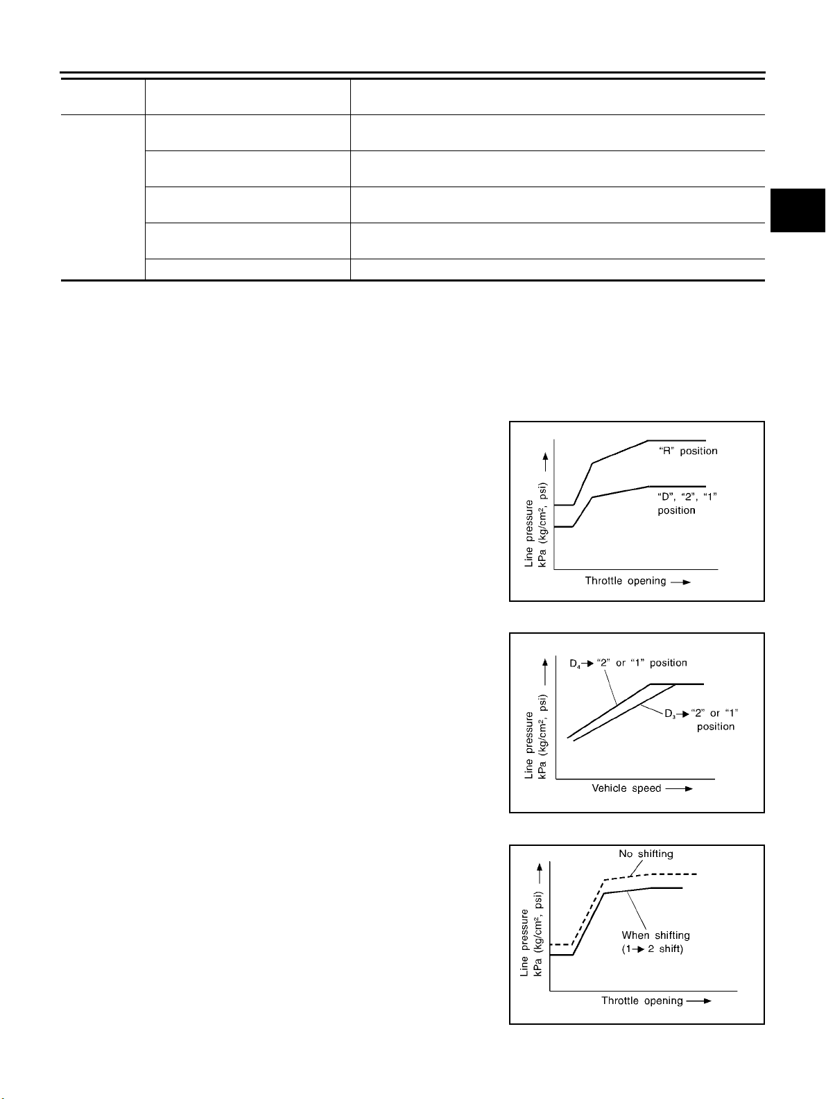
LINE PRESSURE CO NTR O L
TCM has various line pressure control characteristics to match the driving conditions.
An ON-OFF duty signal is sent to the line pressure solenoid valve based on TCM characteristics.
Hydraulic pressure on the clutch and brake is electronically controlled through the line pressure solenoid valve
to accommodate engine torque. This results in smooth shift operation.
Normal Control
The line pressure to throttle opening characteristics is set for suitable
clutch operation.
A
B
AT
D
E
F
G
H
Back-up Control (Engine brake)
If the selector lever is shifted to “2” position while driving in D4 (OD)
3 ,greatdrivingforceisappliedtotheclutchinsidethetransmis-
or D
sion. C lutch operating pressure (line pressure) must be increased t o
deal with this driving force.
During Shift Change
The line pressure is temporarily reduced corresponding to a change
in engine torque when shifting gears (that is, when the shift solenoid
valve is switched for clutch operation) to reduce shifting shock.
SAT003J
SAT004J
I
J
K
L
M
AT-29
SAT005J
Page 34
OVERALL SYSTEM
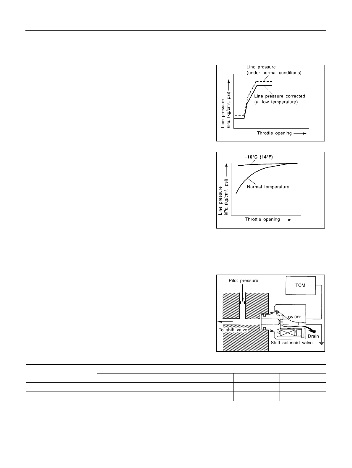
At Low Fluid Temperature
● Fluid viscosity and frictional characteristics of the clutch facing change with fluid temperature. Clutch
engaging or b and-contacting pressure is compensated for, according to fluid temperature, to stabilize
shifting quality.
● The line pressure is reduced below 60°C(140°F) to prevent
shifting shock due to low viscosity of automatic transmission
fluid when temperature is low.
SAT006J
● Line pressure is increas ed to a maximum irrespective of the
throttle opening when fluid temper ature drops to −10°C(14°F).
This pressure rise is adopted to prevent a delay in clutch and
brake operation due to extreme drop of fluid viscosity at low
temperature.
SAT007J
SHIFT CONTROL
The shift is regulated entirely by electronic control to accommodate vehicle speed and varying engine operations. This is accomplished by electrical signals transmitted by the revolution sensor and throttle position sensor. This results in improved acceleration performance and fuel economy.
Control of Shift Solenoid Valves A and B
The TCM activates shift solenoid valves A and B according to signals from the throttle position sensor and revolution sensor to select
the optimum gear position on the basis of the shift schedule memorized in the TCM.
The shift solenoid valve performs simple ON-OFF operation. When
set to “ON”, the drain circuit closes and pilot pressure is applied to
the shift v alve.
SAT008J
Relation Between Shift Solenoid Valves A and B and Gear Positions
Shift solenoid valve
AON(Closed)OFF(Open)OFF(Open)ON(Closed)ON(Closed)
BON(Closed)ON(Closed)OFF(Open)OFF(Open)ON(Closed)
D
1 ,21 ,11 D2 ,22 ,12 D3 D4 (OD) N-P
Gear position
AT-30
Page 35
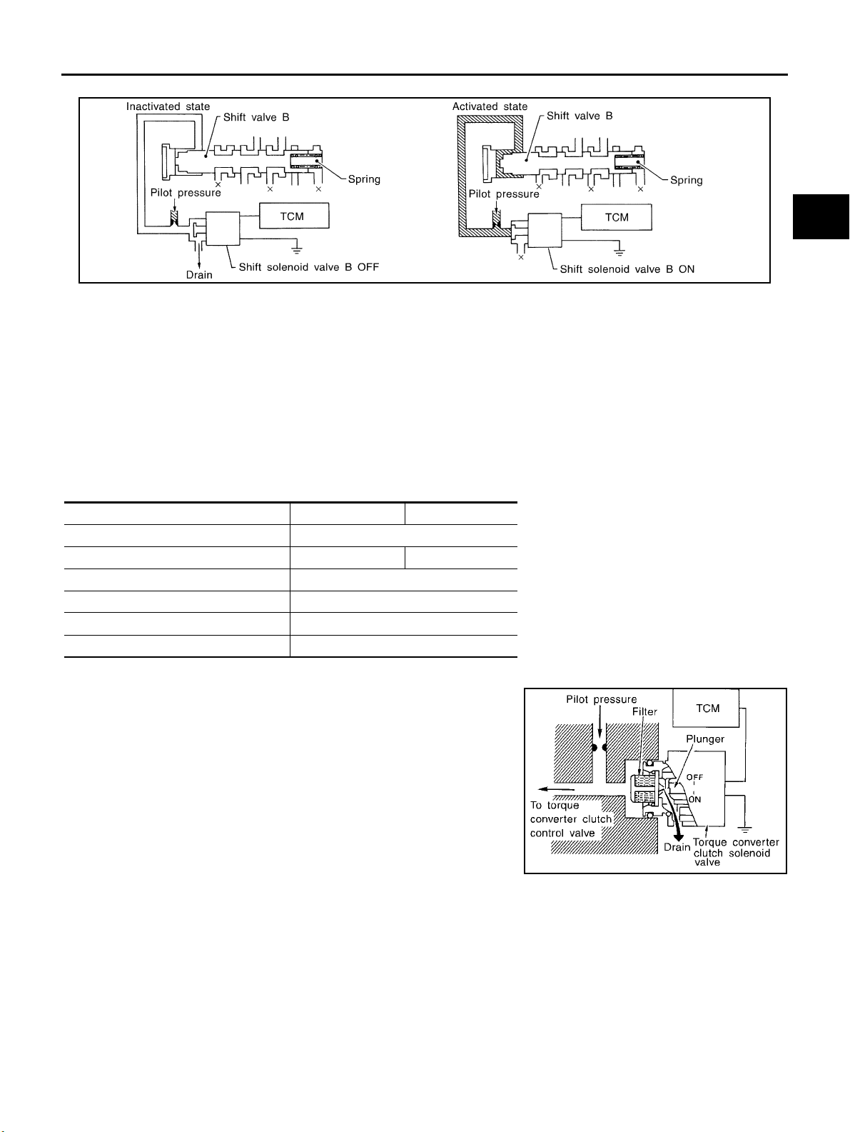
Control of Shift Valves A and B
OVERALL SYSTEM
A
B
AT
SAT009J
Pilot pressure generated by the operation of shift solenoid valves A and B is applied to the end face of shift
valves A and B.
The d rawing above shows the operation of shift valve B. When the shift solenoid valve is “ON”, pilot pressure
applied to the end face of the shift valve overcomes spring force, moving the valve upward.
LOCK-UP CONTROL
The torque converter clutch piston in the torque converter is locked to eliminate torque converter slip to
increase power transmission efficiency. The solenoid valve is con trolled by an ON-OFF duty signal sent from
the TCM. The signal is converted to an oil pressure signal which controls the torque converter clutch piston.
Conditions for Lock-up Operation
When vehicle is driven in 4th gear position, vehicle speed and throttle opening are detected. If the detected
values fall within the lock-up zone memorized in the TCM, lock-up is performed.
Overdrive control switch ON OFF
Selector lever “D” position
Gear position D
Vehicle sp eed sensor More than set value
Throttle position sensor Less than set opening
Closed throttle position switch OFF
A/T fluid temperature sensor More than 40°C(104°F)
4 D3
Torque Conv erter Clutch Soleno id Valve Control
The torque converter clutch solenoid valve is controlled by the TCM.
The plunger closes the drain circuit during the “OFF” period, and
opens the circuit during the “ON” period. If the percentage of OFFtime increases in one cycle, the pilot pressure drain time is reduced
and pilot pressure remains high.
D
E
F
G
H
I
J
K
L
AT-31
M
SAT010J
Page 36
OVERALL SYSTEM
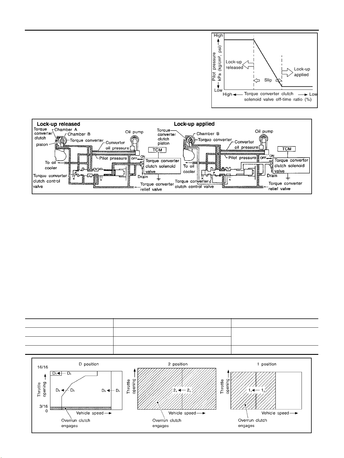
The torque converter clutch piston is designed to slip to adjust the
ratio of ON-OFF, thereby reducing lock-up shock.
OFF-time INCREASING
↓
Amount of dr ain DECREASING
↓
Pilot pressure HIGH
↓
Lock-up RELEASING
Torque Converter Clutch Control Valv e Opera tion
SAT011J
AAT155A
Lock-up released
The OFF-duration of the torque converter clutch solenoid valve is long, and pilot pressure is high. The pilot
pressure pushes the end face of the torque converter clutch control valve in combination with spring force to
move the valve to the left. As a result, c onverter pressure i s applied to chamber A (torque converter clutch piston release side). Accordingly, the torque converter clutch pi ston remains unlocked.
Lock-up applied
When the OFF-duration of the torque converter clutch solenoid valve is short, pilot pressure drains and
becomes low. Accordingly, the control valv e moves to the right by the pilot pressure of the other circuit and
converter pressure. As a result, converter pressure is applied to chamber B, keeping the torque converter
clutch piston applied.
Also smooth lock-up is provided by transient application and release of the lock-up.
OVERRUN CLUTCH CONTROL (ENGINE BRAKE CONTROL)
Forward one-way clutch is used to reduce shifting shocks in downshifting operations. This clutch transmits
engine torque to the wheels. However, drive force from the wheels is not transmitted to the engine because
the one-way clutch rotates idle. This m eans the engine brake is not effective.
The overrun clutch operates when the engine brake is needed.
Overrun Clutch Operating Conditions
Selector lever position Gear position Throttle opening
“D” position → move to center D
“2” position → move to center 2
“1” position → move to center 1
1 ,D2 ,D3 gear position
1 ,22 gear position
1 ,12 gear position At any position
Less than 3/16
AT-32
SAT014J
Page 37
OVERALL SYSTEM
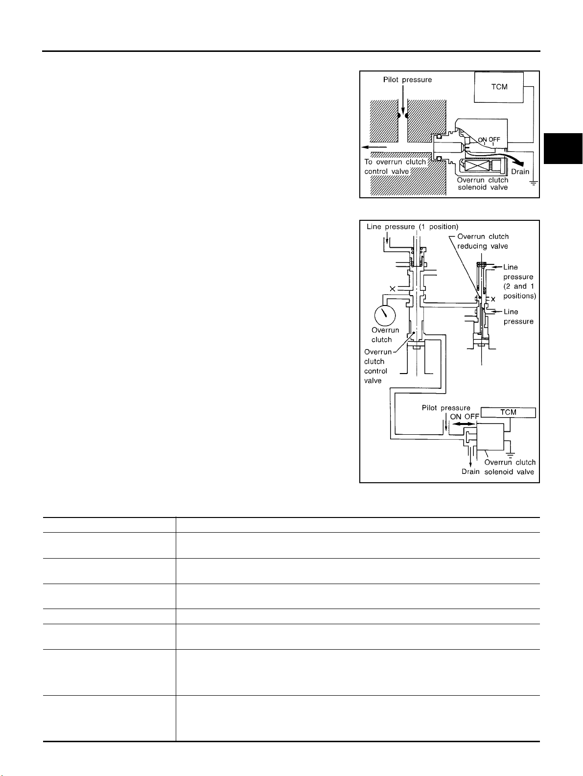
Overrun Clutch Solenoid Valve Control
The overrun clutch solenoid valve is operated by an ON-OFF signal
transmitted by the TCM to provide overrun clutch control (engine
brake control).
When this solenoid valve is “ON”, the pilot pressure drain port
closes. When it is “OFF”, the drain port opens.
During the solenoid valve “ON” pilot pressure is applied to the end
face of the overrun clutch control valve.
A
B
AT
Overrun Clutch Control Valve Operation
When the solenoid valve is “ON”, pilot pressure is applied to the
overrun clutch control valve. This pushes up the overrun clutch control valve. The line pressure is then shut off so that the clutch does
not engage.
When the solenoid valve is “OFF”, pilot pressure is not generated. At
this point, the overrun clutch control valve moves downward by
spring force. As a result, overrun clutch operation pressure is provided by the overrun clutch reducing valve. This causes the overrun
clutch to engage.
In the 1 position, the overrun clutch control valve remains pushed
down so that the overrun clutch is engaged at all times.
SAT015J
SAT016J
D
E
F
G
H
I
J
K
Control Valve
ECS004QG
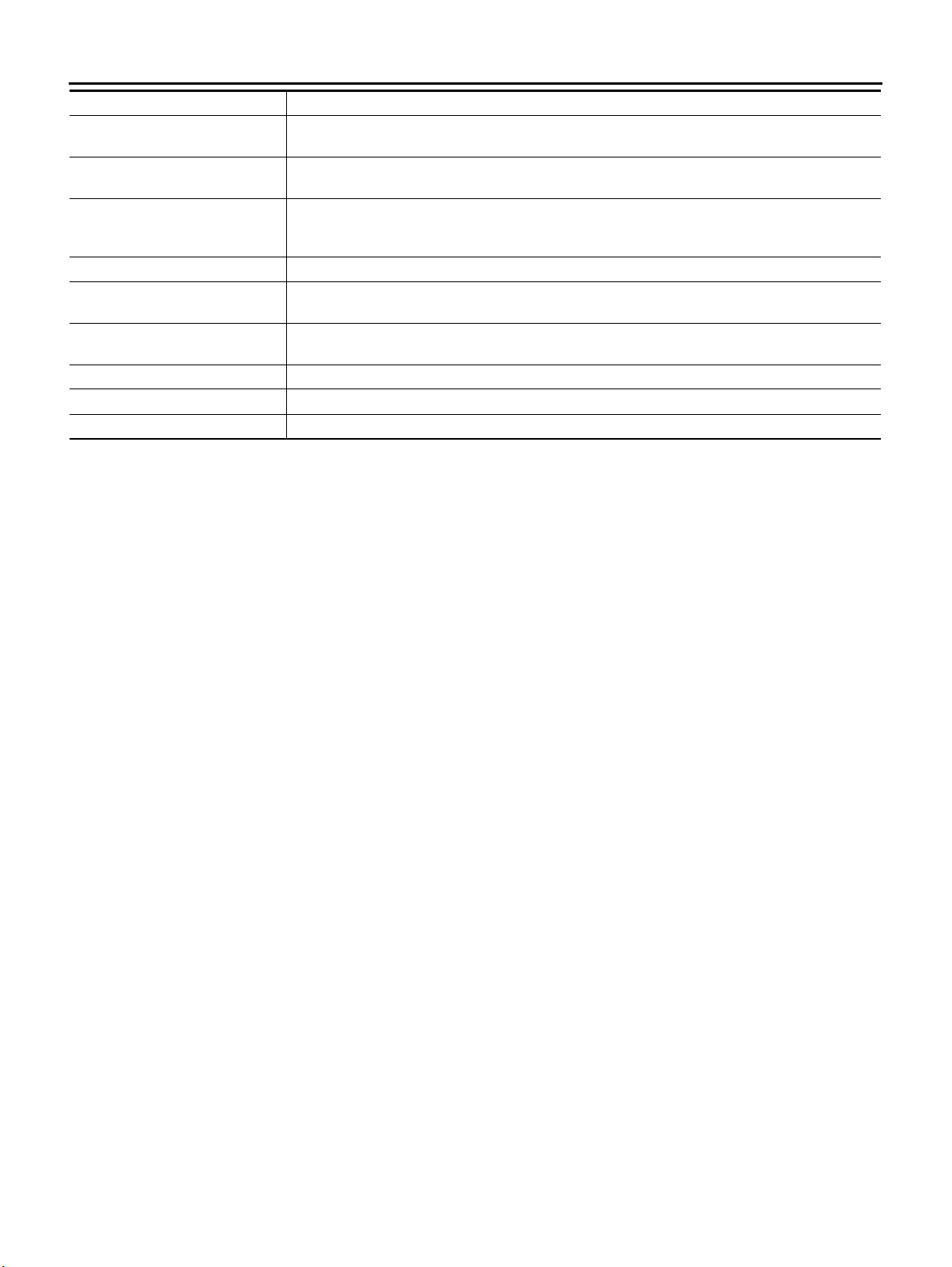
FUNCTION OF CONTROL VALVES
Val ve n ame Function
Pressure regulator valve, plug
and sleeve
Pressure modifier valve and
sleeve
Pilot valve Regulates line pressure to maintain a constant pilot pressure level which controls lock-up mecha-
Accumulator control valve Regulates accumulator back-pressure to pressure suited to driving conditions.
Manual valve Directs line pressure to oil circuits corresponding to select positions.
Shift valve A Simultaneously switches four oil circuits using output pressure of shift solenoid valve A to meet
Shift valve B Simultaneously switches three oil circuits using output pressure of shift solenoid valve B in rela-
Regulates oil discharged from the oil pump to provide optimum line pressure for all driving conditions.
Used as a signal supplementary valve to the pressure regulator valve. Regulates pressure-modifier pressure (signal pressure) which controls optimum line pressure for all driving conditions.
nism, overrun clutch, shift timing.
Hydraulic pressure drains when the shift lever is in Neutral.
driving conditions (vehicle speed, throttle opening, etc.).
Provides automatic downshifting and up-shifting (1st → 2nd → 3rd → 4th gears/4th → 3rd → 2nd
→ 1st gears) in combination with shift valve B.
tion to driving conditions (vehicle speed, throttle opening, etc.).
Provides automatic downshifting and up-shifting (1st → 2nd → 3rd → 4th gears/4th → 3rd → 2nd
→ 1st gears) in combination with shift valve A.
AT-33
L
M
Page 38
OVERALL SYSTEM
Valv e name Functio n
Overrun clutch control valve Switches hydraulic circuits to prevent engagement of the overrun clutch simultaneously with appli-
cation of the brake band in D
1st reducing valve Reduces low & reverse brake pressure to dampen engine-brake shock when down-shifting from
the “1” position 1
Overrun clutch reducing valve Reduces oil pressure directed to the overrun clutch and prevents engine-brake shock.
In “1” and “2” positions, line pressure acts on the overrun clutch reducing valve to increase the
pressure-regulating point, with resultant engine brake capability.
To r q u e conv e r t er re l i e f v al ve Pr ev e nt s a n e xc es si ve r is e in t o r q ue co n v e rt e r pres s u r e.
To r q u e c onv e r t er c lu t ch c on tr ol
valve, plug and sleeve
1-2 accumulator valve and piston Dampens the shock encountered when 2nd gear band servo contracts, and provides smooth
3-2 timing valve Switches oil pressure with 3-2 timing valve according to throttle opening.
Shuttle control valve Reduces shock when down-shifting from 3rd to 2nd and regulates overrun clutch.
Cooler check valve Regulates oil pressure which causes lock-up when driving at low speeds.
Activates or inactivates the lock-up function.
Also provides smooth lock-up through transient application and release of the lock-up system.
shifting.
2 to 11 .
4 .(InterlockingoccursiftheoverrunclutchengagesduringD4 .)
AT-34
Page 39
TROUBLE DIAGNOSIS — INDEX
[EURO-OBD]
[EURO-OBD]
TROUBLE DIAGNOSIS — INDEX PFP:00000
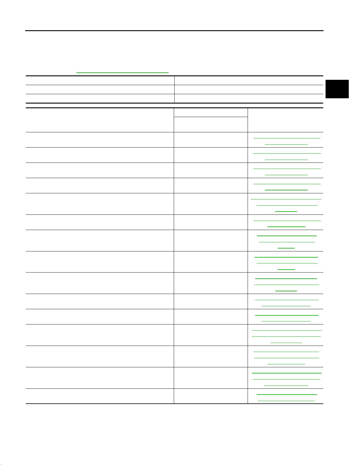
Alphabetical & P No. Index for DTC
ALPHABETICAL INDEX FOR DTC
Check if the vehicle is a model with Euro-OBD system or not by the “Type approval number” on the identification plate. Refer toGI-45, "
Type ap proval number Model
Not available (blank) Without Euro-OBD system
IDENTIFICATION PLATE" .
Available With Euro-OBD system
ECS003VK
A
B
AT
Items
(CONSULT-II screen terms)
A/T 1ST GR FNCTN P0731
A/T 2ND GR FNCTN P0732
A/T 3RD GR FNCTN P0733
A/T 4TH GR FNCTN P0734
ATF TEMP SEN/CIR C P0710
ENGINE SPEED SIG P0725
L/PRESS SOL/CIRC P0745
O/R CLTCH SOL/CIRC P1760
PNP SW/CIRC P0705
SFT SOL A/CIRC*2 P0750
SFT SOL B/CIRC*2 P0755
TCC SOLENOID/CIRC P0740
TP SEN/CIRC A/T*2 P1705
VEH SPD SEN/CIR AT*3 P0720
CAN COMM CIRCUIT U1000
DTC
CONSULT-II
GST*1
Reference page
AT-1 51, "
AT-1 58, "
AT-1 65, " DTC P0733 A/T 3RD
AT-1 72, "
AT-1 36, "
AT-1 47, "
AT-2 08, "
AT-1 30, "
NEUTRAL POSITION (PNP)
AT-1 93, "
AT-1 98, " DTC P0755 SHIFT
AT-18 1, "
CONVERTER CLUTCH SOLE-
AT-2 03, "
ERATOR PEDAL POSITION
AT-1 4 2, "
SPEED SENSOR·A/T (REVO-
DTC P0731 A/T 1ST
GEAR FUNCTION"
DTC P0732 A/T 2ND
GEAR FUNCTION"
GEAR FUNCTION"
DTC P0734 A/T 4TH
GEAR FUNCTION"
DTC P0710 A/T FLUID
TEMPERATURE SENSOR
CIRCUIT"
DTC P0725 ENGINE
SPEED SIGNAL"
AT-18 6, "
PRESSURE SOLENOID
RUN CLUTCH SOLENOID
EC-114, "
COMMUNICATION LINE"
DTC P0745 LINE
VALV E "
DTC P1760 OVER-
VALV E "
DTC P0705 PARK/
SWITCH"
DTC P0750 SHIFT
SOLENOID VALVE A"
SOLENOID VALVE B"
DTC P0740 TORQUE
NOID VALVE"
DTC P1705 ACCEL-
(APP) SENSOR"
DTC P0720 VEHICLE
LUTION SENSOR)"
DTC U1000 CAN
D
E
F
G
H
I
J
K
L
M
● *1: These numbers are prescribed by SAE J2012.
● *2: When the fail-safe operation occurs, the MIL illuminates.
● *3: The MIL illuminates when both the “Revolution sensor signal” and the “Vehicle speed sensor signal” meet the fail-safe condition at
the same time.
AT-35
Page 40
TROUBLE DIAGNOSIS — INDEX
[EURO-OBD]
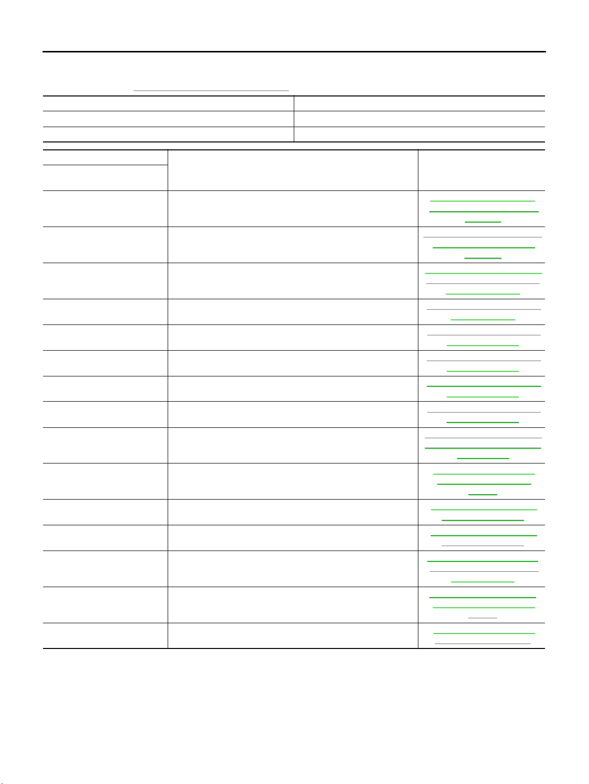
PNO.INDEXFORDTC
Check if the vehicle is a model with Euro-OBD system or not by the “Type approval number” on the identification plate. Refer to GI-45, "
Type ap proval n umber Model
Not available (blank) Without Euro-OBD system
IDENTIFICATION PLATE" .
Available With Euro-OBD system
DTC
CONSULT-II
GST*1
P0705 PNP SW/CIRC
P0710 ATF TEMP SEN/CIRC
P0720 VEH SPD SEN/CIR AT*3
P0725 ENGINE SPEED SIG
P0731 A/T 1ST GR FNCTN
P0732 A/T 2ND GR FNCTN
P0733 A/T 3RD GR FNCTN
P0734 A/T 4TH GR FNCTN
P0740 TCC SOLENOID/CIRC
P0745 L/PRESS SOL/CIRC
P0750 SFT SOL A/CIRC*2
P0755 SFT SOL B/CIRC*2
P1705 TP SEN/CIRC A/T*2
P1760 O/R CLTCH SOL/CIRC
U1000 CAN COMM CIRCUIT
Items
(CONSULT-II screen terms)
Reference page
AT-1 30, "
NEUTRAL POSITION (PNP)
AT- 1 3 6 , "
TEMPERATURE SENSOR
AT-1 42, "
SPEED SENSOR·A/T (REVO-
AT-1 47, "
AT-1 51, "
AT-1 58, "
AT-1 65, "
AT-1 72, " DTC P0734 A/T 4TH
AT-18 1, "
CONVERTER CLUTCH SOLE-
AT-1 8 6, "
AT-19 3, "
AT-19 8, " DTC P0755 SHIFT
AT-2 03, "
ERATOR PEDAL POSITION
AT- 2 0 8 , "
RUN CLUTCH SOLENOID
EC-114, "
DTC P0705 PARK/
SWITCH"
DTC P0710 A/T FLUID
CIRCUIT"
DTC P0720 VEHICLE
LUTION SENSOR)"
DTC P0725 ENGINE
SPEED SIGNAL"
DTC P0731 A/T 1ST
GEAR FUNCTION"
DTC P0732 A/T 2ND
GEAR FUNCTION"
DTC P0733 A/T 3RD
GEAR FUNCTION"
GEAR FUNCTION"
DTC P0740 TORQUE
NOID VALVE"
DTC P0745 LINE
PRESSURE SOLENOID
VALV E "
DTC P0750 SHIFT
SOLENOID VALVE A"
SOLENOID VALVE B"
DTC P1705 ACCEL-
(APP) SENSOR"
DTC P1760 OVER-
VALV E "
DTC U1000 CAN
COMMUNICATION LINE"
● *1: These numbers are prescribed by SAE J2012.
● *2: When the fail-safe operation occurs, the MIL illuminates.
● *3: The MIL illuminates when both the “Revolution sensor signal” and the “Vehicle speed sensor signal” meet the fail-safe condition at
the same time.
AT-36
Page 41
ON BOARD DIAGNOSTIC SYSTEM DESCRIPTION
[EURO-OBD]
ON BOARD DIAGNOSTIC SYSTEM DESCRIPTION PFP:00000
Introduction
The A/T system has two self-diagnostic systems.
The first is the emission-related on board diagnostic system (EURO-OBD) performed by the TCM in combination with the ECM. The malfunction is indicated by the MIL (malfunction indicator lamp) and is stored as a DTC
in t he ECM m emory but not the TCM memory.
The second is the TCM original self-diagnosis indicated by the O/D OFF indicator lamp. The malfunction is
stored in the TCM memory. The detected items are overlapped w ith EURO-OBD self-diagnostic items. For
detail, refer to AT-42, "
SELF-DIAGNOSTIC RESULT TEST MODE" .
ECS004QH
A
B
AT
EURO-OBD Function for A/T System
ECS004QI
The ECM provides emission-related on board diagnostic (EURO-OBD) functions for the A/T system. One
function is to receive a signal from the TCM used with EURO-OBD-related parts of the A/T system. The signal
is sent to the ECM when a malfunction occurs in the corresponding EURO-OBD-related part. The other function is to indicate a diagnostic result by means of the MIL (malfunction indicator lamp) on the instrument panel.
Sensors, switches and solenoid valves are used as sensing elements.
The MIL automatically illuminates in One or Two Trip Detection Logic when a malfunction is sensed in relation
to A/T system parts.
One or Two Trip Detection Logic of EURO-OBD
ECS0 04QJ
ONE TRIP DETECTION LOGIC
If a malfunction is sensed during the first test drive, the MIL will illuminate and the malfunction will be stored in
the ECM memory as a DTC. The TCM is not provided with such a memory function.
TWO TRIP DETECTION LOGIC
When a malfunction is sensed during the first test drive, it is stored in the ECM memory as a 1st trip DTC
(diagnostic trouble code) or 1st trip freeze frame data. At this point, the MIL will not illuminate. — First Trip
If the same malfunction as that experienced during the first test drive is sensed during the second test drive,
the MIL will illuminate. — Second Trip
A/T-related parts for which the MIL illuminates during the first or second test drive are listed below.
Items
Shift solenoid valve A — DTC: P0750 X
Shift solenoid valve B — DTC: P0755 X
Throttle position sensor — DTC: P1705 X
Except above X
One trip detection Two trip detection
MIL
The “trip” in the “One or Two Trip Detection Logic” means a driving mode in which self-diagnosis is performed
during vehicle operation.
EURO-OBD Diagnostic Trouble Code (DTC)
ECS004QK
HOW TO READ DTC AND 1ST TRIP DTC
DTC and 1st trip DTC can be read by the following methods.
(withCONSULT-IIor GST)CONSULT-II or GST (Generic Scan Tool) Examples: P0705, P0710,
P0720, P0725, etc.
These DTCs a re prescribed by SAE J2012.
(CONSULT-II also displays the malfunctioning component o r system.)
● 1st trip DTC No. is the same as DTC No.
● Output of t he diagnostic trouble code indicates that the indicated circuit has a malfunction. How-
ever, in case of the Mode II and GST they do not indicate whether the malfunction is still occurring
or occurred in the past and returned to normal.
CONSULT-II can identify them as shown below. Therefore, using CONSULT-II (if available) is rec-
ommended.
D
E
F
G
H
I
J
K
L
M
AT-37
Page 42
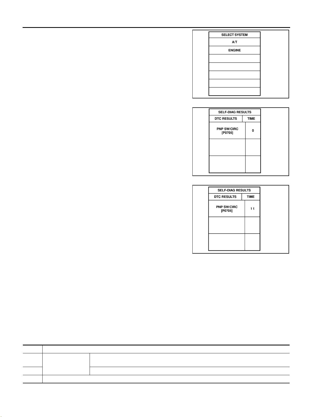
ON BOARD DIAGNOSTIC SYSTEM DESCRIPTION
AsampleofCONSULT-IIdisplayforDTCisshowninthefollowing
page. DTC or 1st trip DTC of a malfunction is displayed in SELF
DIAGNOSIS mode for “ENGINE” with CONSULT-II. Time data indicates how many times the vehicle was driven after the last detection
of a DTC.
If the DTC is being detected currently, the time data wi ll be “0”.
[EURO-OBD]
SAT014K
SAT015K
If a 1st trip DTC is stored in the ECM, the time data will be “1t”.
SAT016K
Freeze Frame Data and 1st Trip Freeze Frame Data
The ECM has a memory function, which stores the driving condition such as fuel system status, calculated
load value, engine coolant temperature, short term fuel trim, long term fuel trim, engine speed and vehicle
speed at the moment the ECM detects a malfunction.
Data which are stored in the ECM memory, along with the 1st trip DTC, are called 1st trip freeze frame data,
and the data, stored together with the DTC data, are called freeze frame data and displayed on CONSULT-II
or GST. The 1st trip freeze frame data can only be displayed on the CONSULT-II screen, not on the GST. For
detail, refer to " ", “CONSULT-II”.
Only one set of freeze frame data (either 1st trip freeze frame data of freeze frame d ata) can be stored in the
ECM. 1st trip freeze frame data is stored in the ECM memory along with the 1st trip DTC. There is no priority
for 1st trip freeze frame data and it is updated e ach time a different 1st trip DTC is detected. However, once
freeze frame data (2nd trip detection/MIL on) is stored in the ECM memory, 1st trip freeze frame data is no
longer stored. Remember, only one set of freeze frame data can be stored in the ECM.
The ECM has the following priorities to update the data.
Priority Items
1Freezeframedata Misfire—DTC:P0300-P0306
Fuel Injection System Function — DTC: P0171, P0172, P0174, P0175
2Excepttheaboveitems(IncludesA/Trelateditems)
31sttripfreezeframedata
Both 1st trip freeze frame data and freeze frame data (along with the DTCs) are cleared when the ECM memory is erased.
AT-38
Page 43

ON BOARD DIAGNOSTIC SYSTEM DESCRIPTION
[EURO-OBD]
HOW TO ERASE DTC
The diagnostic trouble code can be erased by CONSULT-II, GST or ECM DIAGNOSTIC TEST MODE as
described following.
● If the battery terminal is disconnected, the diagnostic trouble code will be lost within 24 hours.
● When you erase the DTC, using CONSULT-II or GST is easier and quicker than switching the mode
selector on the E CM.
The following emission-related diagnostic information is cleared from the ECM memory when erasing DTC
related to EURO-OBD. For details, refer to EC-46, "
INFORMATION" .
● Diagnostic trouble codes (DTC)
● 1st trip diagnostic trouble codes (1st trip DTC)
● Freeze frame data
● 1st trip freeze frame data
● System readiness test (SRT) codes
● Test values
HOW TO ERASE EMISSION-RELATED DIAGNOSTIC
A
B
AT
D
E
HOW TO ERASE DTC (WITH CONSULT-II)
● If a DTC is displa yed for both ECM and TCM, it needs to be erased for both ECM and TCM.
1. If the ignition switch stays “ON” after repair work, be sure to turn ignition switch “OFF” once. Wait at least
5secondsandthenturnit“ON”(enginestopped)again.
2. Turn CONSULT-II “ON” and touch “A/T”.
3. Touch “SELF DIAGNOSIS”.
4. Touch “ERASE”. (The DTC in the TCM will be erased.) Then touch “BACK” twice.
5. Touch “ENGINE”.
6. Touch “SELF DIAGNOSIS”.
F
G
H
I
J
K
L
M
AT-39
Page 44
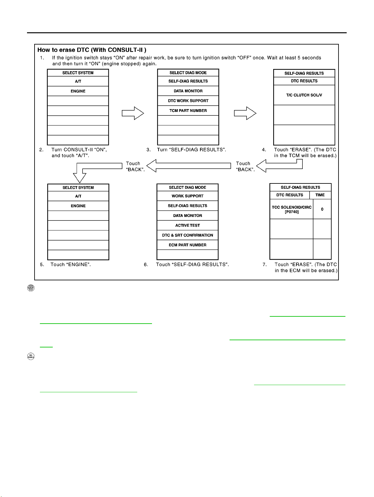
ON BOARD DIAGNOSTIC SYSTEM DESCRIPTION
7. Touch “ERASE”. (The DTC in the ECM will be erased.)
[EURO-OBD]
SAT017K
HOW TO ERASE DTC (WITH GST)
1. If the ignition switch stays “ON” after repair work, be sure to turn ignition switch “OFF” once. Wait at least
5secondsandthenturnit“ON”(enginestopped)again.
2. Perform “EURO-OBD SELF-DIAGNOSTIC PROCEDURE (No Tools)”. Refer to AT- 5 1, "
NOSTIC PROCEDURE (NO TOOLS)" .(Theenginewarm-upstepcanbeskippedwhenperformingthe
diagnosis only to erase the DTC.)
3. Select Mode 4 with Generic Scan Tool (GST). For details, refer to EC-96, "
tion" ,“GenericScanTool(GST)”.
Generic Scan Tool (GST) Func-
TCM SELF-DIAG-
HOW TO ERASE DTC (NO TOOLS)
1. If the ignition switch stays “ON” after repair work, be sure to turn ignition switch “OFF” once. Wait at least
5secondsandthenturnit“ON”(enginestopped)again.
2. Perform “TCM SELF-DIAGNOSTIC PROCEDU RE (No Tools)”. Refer to AT-51, "
TIC PROCEDURE (NO TOOLS)" .(Theenginewarm-upstepcanbeskippedwhenperformingthediag-
nosis only to erase the DTC.)
TCM SELF-DIAGNOS-
AT-40
Page 45
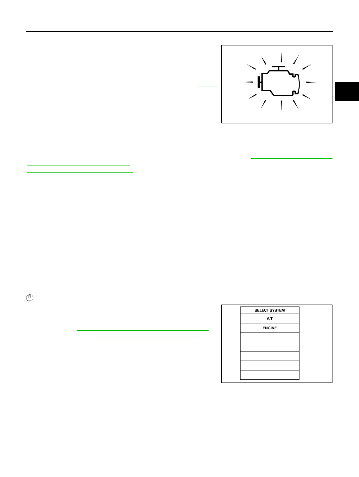
ON BOARD DIAGNOSTIC SYSTEM DESCRIPTION
[EURO-OBD]
Malfunction Indicator lamp (MIL)
ECS004QL
1. The malfunction indicator lamp will light up when the ignition
switch is turned ON w ithout the engine running. This is for
checking the lamp.
● If the malfunction indicator does not light up, refer to "",
“Warning Lamps”.
(Or see MIL & CONSULT-II in EC section. Refer to EC-48,
"Malfunctio n Indicator (MI)" ,“Description”,“MalfunctionIndi-
cator lamp (MIL)” and " ", “CONSULT-II”.)
2. When the engine is started, the malfunction indicator should go
off.
If the lamp rem ains on, the on bo ard diagnostic system has
SAT652J
detected an emission-related (EURO-OBD) malfunction. For
detail, refer to "njec0029", “ON BOARD DIAGNOS TIC SYSTEM DESCRIPTION”.
CONSULT-II
ECS0 04QM
After performing “SELF-DIAGNOSTIC PROCEDURE (WITH CONSULT-II)” AT-41, " SELF-DIAGNOSTIC
PROCEDURE (WITH CONSULT-II)" ,placecheckmarksforresultsonthe“DIAGNOSTICWORKSHEET”,
AT-57 , "
DIAGNOSTIC WORKSHEET" .Referencepagesareprovidedfollowingtheitems.
NOTICE:
1. The CONSULT-II electrically displays shift timing and lock-up timing (that is, operation timing of each solenoid).
Check for time difference between actual shift timing and the CONSULT-II display. If the difference is
noticeable, mechani cal parts (except solenoids, sensors, etc.) may be malfunctioning. Check mechanic al
parts using applicable diagnostic procedures.
2. Shift schedule (which implies gear position) displayed on CONSULT-II and that indicated in Service Manual may differ slightly. This occurs because of the following reasons:
– Actual shift schedule has more or less tolerance or allowance,
– Shift schedule indicated in S ervice Manual refers to the point where shifts start, and
– Gear position displayed on CONSULT-II indicates the p oint where shifts are completed.
3. Shift solenoid valve “A” or “B” is displayed on CONSULT-II at the start of shifting. Gear position is displayed upon completion of shifting (which is computed by TCM).
4. Additional CONSULT-II information can be found in the Operation Manual supplied with the CONSULT-II
unit.
A
B
AT
D
E
F
G
H
I
J
K
SELF-DIAGNOSTIC PROCEDURE (WITH CONSULT-II)
1. Turn on CONSULT-II and touch “ENGINE” for EURO-OBD
detected items or touc h “A/T” for TCM self-diagnosis.
If A/T is not displayed, check TCM pow er supply and ground circuit. Refer to AT-125, "
result is NG, refer to PG-2, "
TCM Terminals and Reference Value" .If
POWER SUPPLY ROUTING" .
AT-41
L
M
SAT014K
Page 46
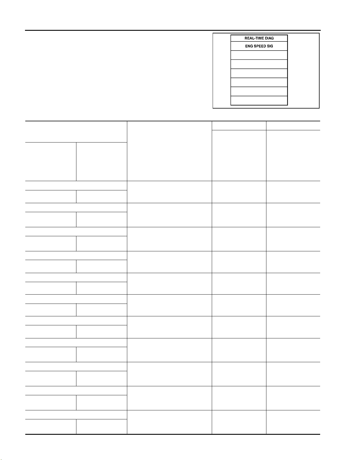
ON BOARD DIAGNOSTIC SYSTEM DESCRIPTION
2. Touch “SELF DIAGNOSIS”.
Display shows malfunction experienced since the last erasing
operation.
CONSULT-II performs “real time diagnosis”.
Also, any malfunction detected while in this mode will be di splayed at real ti me.
SELF-DIAGNOSTIC RESULT TEST MODE
Detected items
(Screen terms for CONSULT-II, “SELF
DIAGNOSIS” test mode)
[EURO-OBD]
SAT987J
TCM self-diagnosis EURO-OBD (DTC)
“A/T” “ENGINE”
Park/neutral position (PNP) switch circuit
—
Revolution sensor
VHCL SPEED
SEN·A/T
Vehicl e speed sensor (M ete r)
VHCL SPEED
SEN·MTR
A/T 1st gear function
—
A/T 2nd gear function
—
A/T 3rd gear function
—
A/T 4th gear function
—
Shift solenoid valve A
SHIFT SOLENOID/VASFT SOL A/CIRC
PNP SW/CIRC
VEH SPD SEN/CIR
AT
—
A/T 1ST GR FNCTN
A/T 2ND GR FNCTN
A/T 3RD GR FNCTN
A/T 4TH GR FNCTN
Malfunction is detected when ...
● TCM does not receive the correct
voltage signal (based on the gear
position) from the switch.
● TCM does not receive the proper
voltage signal from the sensor.
● TCM does not receive the proper
voltage signal from the sensor.
● A/T cannot be shifted to the 1st
gear position even if electrical circuit is good.
● A/T cannot be shifted to the 2nd
gear position even if electrical circuit is good.
● A/T cannot be shifted to the 3rd
gear position even if electrical circuit is good.
● A/T cannot be shifted to the 4th
gear position even if electrical circuit is good.
● TCM detects an improper voltage
drop when it tries to operate the
solenoid valve.
Available by O/D OFF
indicator lamp or “A/T”
on CONSULT-II
—P0705
XP0720
X—
—P0731*1
—P0732*1
—P0733*1
—P0734*1
XP0750
Available by malfunc-
tion indicator*2,
“ENGINE” on CON-
SULT -II or GST
Shift solenoid valve B
SHIFT SOLENOID/VBSFT SOL B/CIRC
Overrun clutch solenoid valve
OVERRUNCLUTCH
S/V
T/C clutch solenoid valve
T/C CLUTCH SOL/V TCC SOLENOID/
O/R CLUCH SOL/
CIRC
CIRC
● TCM detects an improper voltage
drop when it tries to operate the
solenoid valve.
● TCM detects an improper voltage
drop when it tries to operate the
solenoid valve.
● TCM detects an improper voltage
drop when it tries to operate the
solenoid valve.
AT-42
XP0755
XP1760
XP0740
Page 47
ON BOARD DIAGNOSTIC SYSTEM DESCRIPTION
[EURO-OBD]
Detected items
(Screen terms for CONSULT-II, “SELF
DIAGNOSIS” test mode)
Malfunction is detected when ...
“A/T” “ENGINE”
Line pressure solenoid valve
LINE PRESSURE S/VL/PRESS SOL/CIRC
Throttle position sensor (Accelerator Pedal
Position (APP) sensor)
THROTTLE POSI
SEN
Engine speed signal ● TCM does not receive the proper
ENGINE SPEED SIG
A/T fluid temperature sensor
BATT/FLUID TEMP
SEN
Engine control
A/T COMM LINE
TCM (RAM) ● TCM memory (RAM) is malfunc-
CONTROL UNIT
(RAM)
TCM (ROM)
CONTROL UNIT
(ROM)
TCM (EEP ROM)
CONT UNIT (EEP
ROM)
Initial start
INITIAL START
No failure
(NO SELF DIAGNOSTIC FAILURE INDICATED FURTHER TESTING MAY BE
REQUIRED**)
X: Applicable
—: Not applicable
*1: These malfunctions cannot be displayed by MIL if another malfunction is assigned to lamp MIL.
*2: Refer to EC-48, "
*3: A/T COMM LINE means CAN COMM LINE in this model.
TP SEN/CIRC A/T
ATF T EMP SEN /
CIRC
*3
Malfunction Indicator (MI)" ,“MalfunctionIndicatorlamp(MIL)”.
—
—
—
—
—
● TCM detects an improper voltage
drop when it tries to operate the
solenoid valve.
● TCM receives an excessively low
or high voltage from the sensor.
voltage signal from the ECM.
● TCM receives an excessively low
or high voltage from the sensor.
● The ECM-A/T communication line
is open or shorted.
tioning.
● TCM memory (ROM) is malfunc-
tioning.
● TCM memory (EEP ROM) is mal-
functioning.
● This is not a malfunction message
(Whenever shutting off a power
supply to the TCM, this message
appears on the screen.)
● No failure has been detected.
TCM self-diagnosis EURO-OBD (DTC)
Available by O/D OFF
indicator lamp or “A/T”
on CONSULT-II
A
Available by malfunc-
tion indicator*2,
“ENGINE” on CON-
SULT-II or GST
XP0745
B
AT
D
XP1705
XP0725
XP0710
XU1000
E
F
G
H
——
I
——
J
——
K
X—
XX
L
M
AT-43
Page 48
ON BOARD DIAGNOSTIC SYSTEM DESCRIPTION
DATA MONITOR MODE (A/T)
Item Display
Vehicl e sp eed
sensor 1 (A/T)
(Revolution sensor)
Vehicl e sp eed
sensor 2
(Meter)
Throttle position
sensor
A/T fluid temperature sensor
Battery voltage BATTERY VOLT
Engine speed ENGINE SPEED
Overdrive control
switch
PN position (PNP)
switch
Rpositionswitch RPOSITIONSW
Dpositionswitch DPOSITIONSW
2positionswitch 2POSITIONSW
VHCL/S SE·A/T
[km/h] or [mph]
VHCL/S
SE·MTR
[km/h] or [mph]
THRTL POS
SEN
[V]
FLUID TEMP SE
[V]
[V]
[rpm]
OVERDRIVE
SW
[ON/OFF]
PN POSI SW
[ON/OFF]
[ON/OFF]
[ON/OFF]
[ON/OFF]
Mover to center Monitor items
TCM
Input
signals
CAN
comm
sig-
nals
Main
signals
X——
X——
X——
X——
X——
X—X
X——
X——
X——
X——
X——
Selection
from
menu
Description Remarks
● Ve hic le s p eed co m-
puted from signal of
revolution sensor is
displayed.
When racing engine in N
or P with vehicle stationary, CONSULT-II data
may not indicate 0 km/h
(0 mph).
● Ve hic le s p eed co m-
puted from signal of
vehicle speed sensor is
displayed.
Vehicl e speed display
may not be accurate
under approx. 10 km/h
(6 mph). It may not indicate 0 km/h (0 mph)
when vehicle is stationary.
● Throttle position sensor
signal voltage is displayed.
● A/T fluid temperature
This sensor means
accelerator pedal position(app)sensor.
sensor signal voltage is
displayed.
● Signal voltage lowers
as fluid temperature
rises.
● Source voltage of TCM
is displayed.
● Engine speed, com-
puted from engine
speed signal, is displayed.
Engine speed display
may not be accurate
under approx. 800 rpm.
It may not indicate 0 rpm
even when engine is not
running.
● ON/OFF state com-
puted from signal of
overdrive control SW is
displayed.
● ON/OFF state com-
puted from signal of PN
position SW is displayed.
● ON/OFF state com-
puted from signal of R
position SW is displayed.
● ON/OFF state com-
puted from signal of D
position SW is displayed.
● ON/OFF status, com-
puted from signal of 2
position SW, is displayed.
[EURO-OBD]
AT-44
Page 49
ON BOARD DIAGNOSTIC SYSTEM DESCRIPTION
[EURO-OBD]
Item Display
1positionswitch 1POSITIONSW
[ON/OFF]
ASCD cruise signal
ASCD OD cut signal
Kickdown switch KICKDOWN SW
Gear position GEAR
Selector lever
position
Vehicle sp eed VEHICLE
Torque c o n v e r ter
slip ratio
Torque c o n v e r ter
slip speed
can communication
can circuit 1
can circuit 2
can circuit 3
can circuit 4
can circuit 5
ASCD·CRUISE
[ON/OFF]
ASCD·OD CUT
[ON/OFF]
[ON/OFF]
SLCT LVR POSI
SPEED
[km/h] or [mph]
TC SLIP
RATIO
[0.000]
TC SLIP
SPEED
[rpm]
CAN COMM
[OK/UNKWN]
CAN CIRC 1
[OK/UNKWN]
CAN CIRC 2
[OK/UNKWN]
CAN CIRC 3
[OK/UNKWN]
CAN CIRC 4
[OK/UNKWN]
CAN CIRC 5
[OK/UNKWN]
Mover to center Monitor items
TCM
Input
signals
—— X
—— X
—— X
———
———
—X—
—X—
—X—
—X—
—X—
—X—
CAN
comm
sig-
nals
X——
X——
X——
X——
Main
signals
Selection
from
menu
Description Remarks
● ON/OFF status, com-
puted from signal of 1
position SW, is displayed.
● Sta tus of AS CD cruise
signal is displayed.
ON ... Cruising state
OFF ... Normal running state
● Sta tus of ASCD OD
release signal is displayed.
ON ... OD released
OFF ... OD not
released
● ON/OFF status, com-
puted from signal of
kickdown SW, is displayed.
● Gear position data
used for computation
by TCM, is displayed.
● Selector lever position
data, used for computation by TCM, is displayed.
● Vehicle speed data,
used for computation
by TCM, is displayed.
● Ratio of engine revolu-
tion to input shaft revolution of torque
converter
Difference in revolution
between input shaft revolution and input shaft revolution of torque
converter
● This is displayed even
● This is displayed even
● This is displayed even
● Aspecificvalueused
Display doesn't indicate
orpm even if engine is
stopped.
But this isn't malfunction.
when no ASCD is
mounted.
when no ASCD is
mounted.
when no kickdown
switch is equipped.
for c ontrol is displayed
if fail-safe is activated
due to error.
A
B
AT
D
E
F
G
H
I
J
K
L
M
AT-45
Page 50
ON BOARD DIAGNOSTIC SYSTEM DESCRIPTION
Item Display
Throttle position THROTTLE
POSI
[/8]
Stop lamp switch BRAKE SW
[ON/OFF]
Line pressure duty LINE PRES DTY
[%]
To r q u e conv e r t er
clutch solenoid
valve duty
Shift solenoid
valve A
Shift solenoid
valve B
Overrun clutch
solenoid valve
Self-diagnosis display lamp
(O/D OFF indicator lamp)
TCC S/V DUTY
[%]
SHIFT S/V A
[ON/OFF]
SHIFT S/V B
[ON/OFF]
OVERRUN/C S/
V
[ON/OFF]
SELF-D DP LMP
[ON/OFF]
Mover to center Monitor items
TCM
Input
signals
CAN
comm
sig-
nals
Main
signals
——X
X——
——X
——X
——X
——X
——X
——X
Selection
from
menu
Description Remarks
● Throttle position data,
● Aspecificvalueused
used for computation
by TCM, is displayed.
● ON/OFF status is dis-
played.
ON ... Brake pedal is
depressed.
OFF ... Brake pedal is
released.
● Control value of line
pressure solenoid
valve, computed by
TCM from each input
signal, is displayed.
● Control value of torque
converter clutch solenoid valve, computed
by TCM from each
input signal, is displayed.
● Control value of shift
solenoid valve A, computed by TCM from
each input signal, is
displayed.
● Control value of shift
solenoid valve B, com-
Control value of solenoid is displayed even if
solenoid circuit is disconnected.
The OFF signal is displayed if solenoid circuit
is shorted.
puted by TCM from
each input signal, is
displayed.
● Control value of over-
run clutch solenoid
valve computed by
TCM from each input
signal is displayed.
● Control status of O/D
OFF indicator lamp is
displayed.
[EURO-OBD]
for c ontrol is displayed
if fail-safe is activated
due to error.
Voltag e [V] — — — Value me asu red by vol tage probe is displayed.
Value meas ure d by pu lse pro be is disp lay ed. If m ea-
Frequency [Hz] — — —
surement is impossible, "#" sign is displayed. "#"
sign is also displayed at the final data value until the
measurement result is obtained.
DUTY-HI — — —
DUTY-LOW — — —
PLS WIDTH-HI — — —
PLS WIDTH-LOW — — —
Duty cycle value for measurement probe is displayed.
Measured pulse width of measurement probe is displayed.
X: Applicable —: Not applicable : Option
AT-46
Page 51
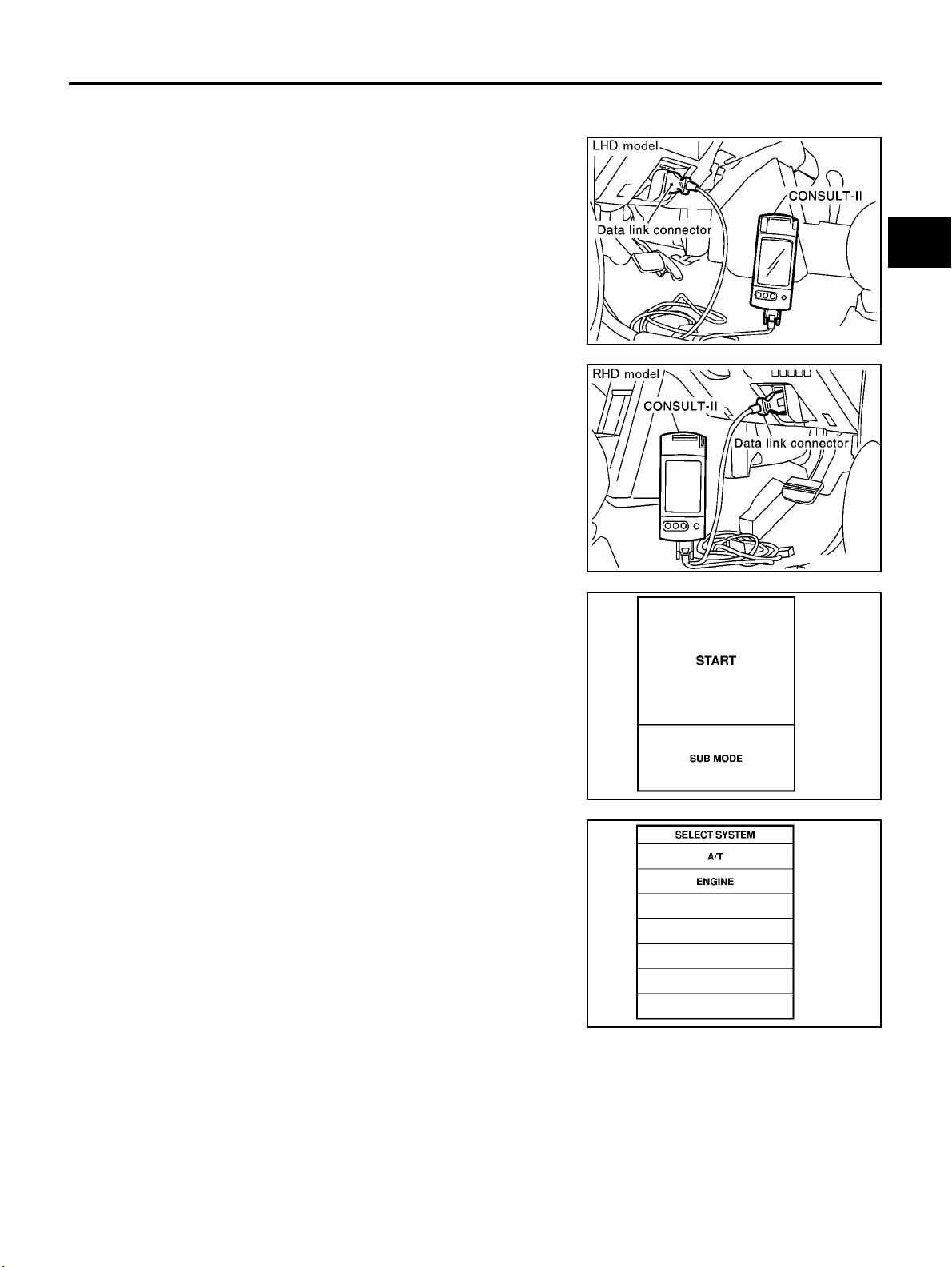
ON BOARD DIAGNOSTIC SYSTEM DESCRIPTION
DTC WORK SUPPORT MODE WITH CONSULT-II
CONSULT-II Setting Procedure
1. Turn ignition switch “OFF”.
[EURO-OBD]
A
B
AT
D
SCIA0691E
2. Connect CONSULT-II to data link connector which is located in
left or right side lower dash panel.
3. Turn ignition switch “ON”.
4. Touch “START”.
5. Touch “A/T”.
SCIA0692E
SAT586J
E
F
G
H
I
J
K
L
AT-47
M
SAT014K
Page 52
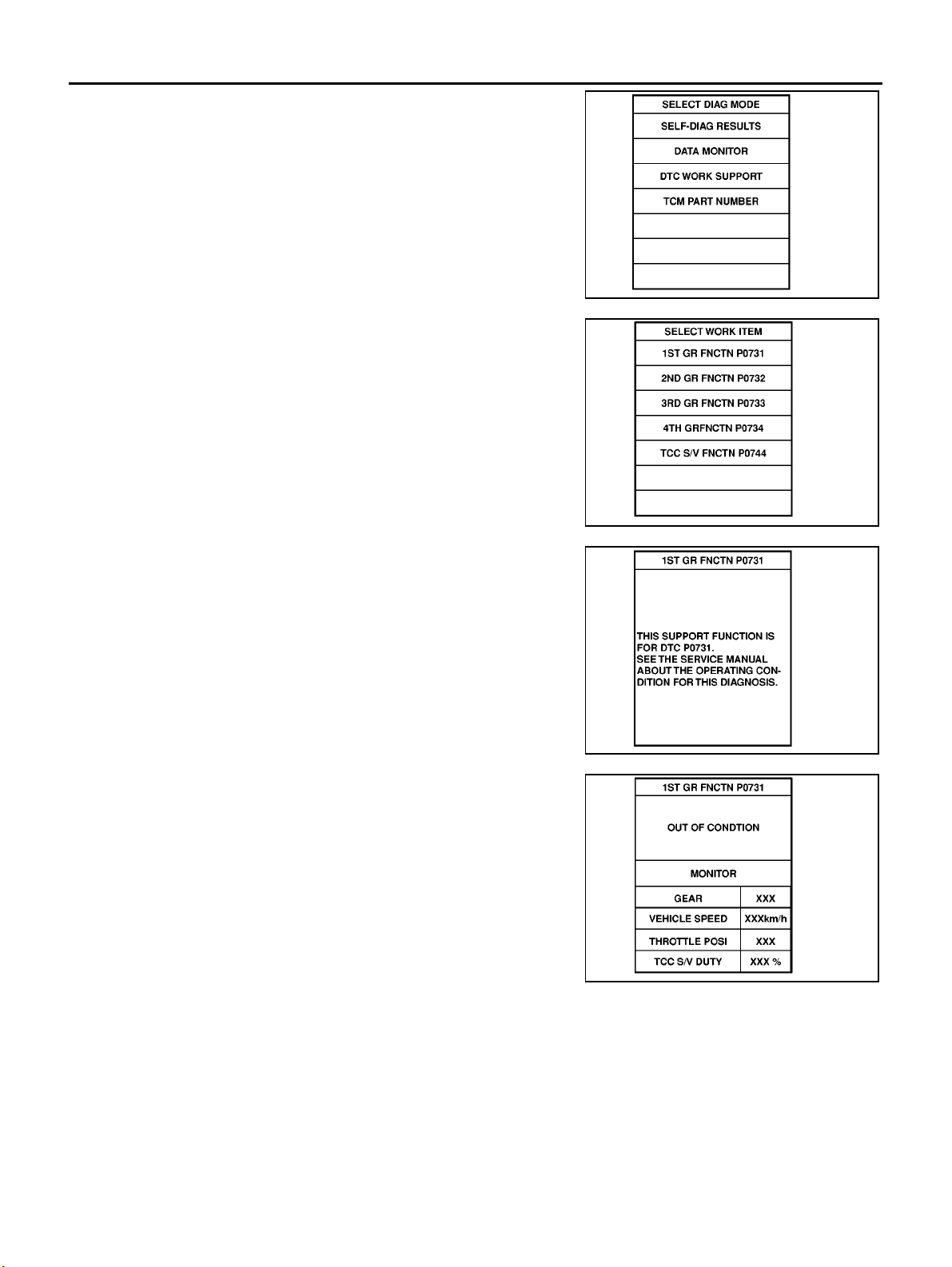
ON BOARD DIAGNOSTIC SYSTEM DESCRIPTION
6. Touch “DT C WORK SUPPORT”.
7. Touch selec t item menu (1ST, 2ND, etc.).
[EURO-OBD]
SAT971J
8. Touch “START”.
9. Perform driving test according to “DTC CO NFIRMATION PROCEDURE” in “TROUBLE DIAGNOSIS FOR DTC”.
SAT018K
SAT589J
SAT019K
AT-48
Page 53
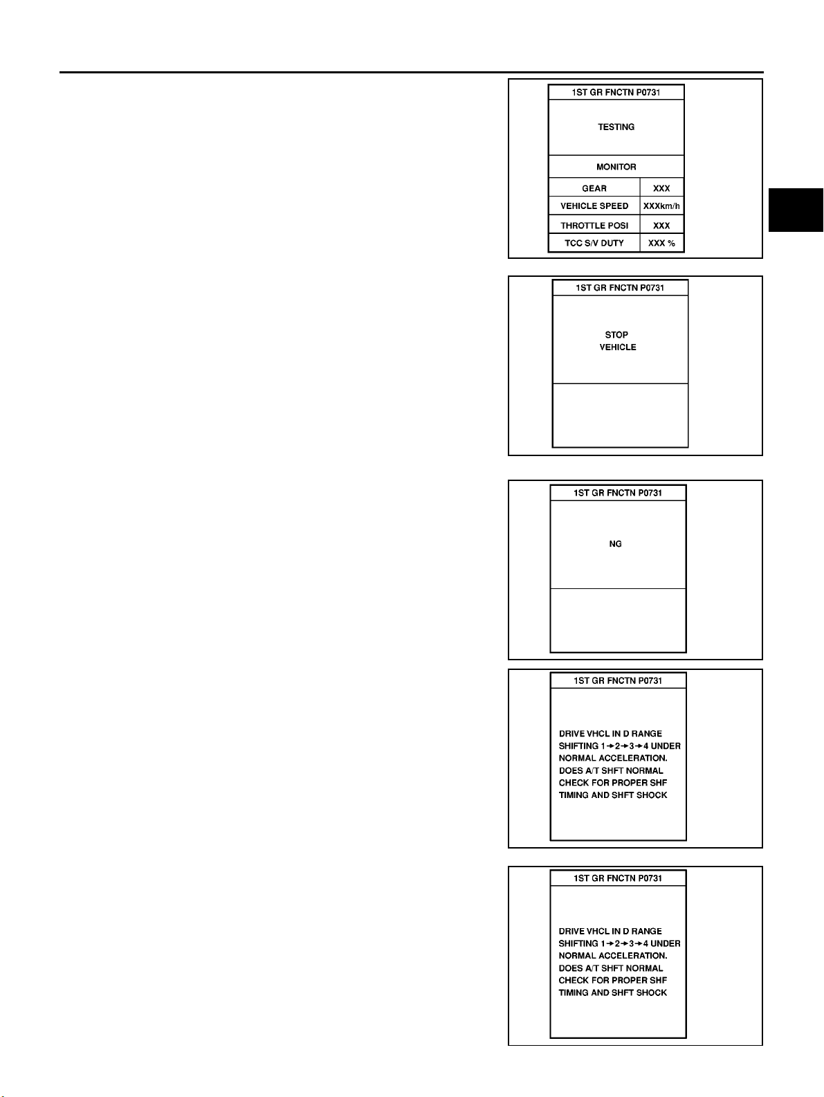
ON BOARD DIAGNOSTIC SYSTEM DESCRIPTION
● When testing conditions are satisfied, CONSULT-II screen
changes from “OUT OF CONDITION” to “TESTING”.
10. Stop vehicle. If “NG” appears on the screen, malfunction may
exist. Go to “DIAGNOSTIC PROCEDURE”.
[EURO-OBD]
A
B
AT
SAT591J
D
E
F
G
SAT592J
11. Perfor m test drive to chec k gear shift feelin g in ac cordanc e with
instructions displayed.
12. Touch “YES” or “NO”.
SAT593J
SAT594J
H
I
J
K
L
M
AT-49
SAT595J
Page 54
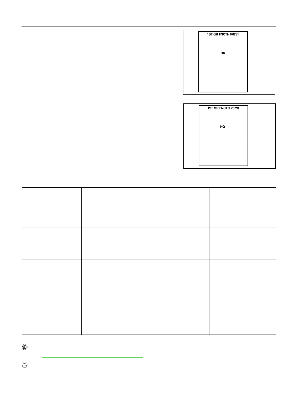
ON BOARD DIAGNOSTIC SYSTEM DESCRIPTION
13. CONSULT-II procedure ended.
[EURO-OBD]
SAT596J
If “NG” appears on the screen , a malfunction may exist. Go to “DIAGNOSTIC PROCEDURE”.
DTC WORK SUPPORT MODE
DTC work support item Description Check items (Possible cause)
1ST GR FNCTN P0731
2ND GR FNCTN P0732
3RD GR FNCTN P0733
4TH GR FNCTN P0734
Following items for “A/T 1st gear function (P0731)” can be confirmed.
● Self-diagnosis status (whether the diagnosis is being conducted
or not)
● Self-diagnosis result (OK or NG)
Following items for “A/T 2nd gear function (P0732)” can be confirmed.
● Self-diagnosis status (whether the diagnosis is being conducted
or not)
● Self-diagnosis result (OK or NG)
Following items for “A/T 3rd gear function (P0733)” can be confirmed.
● Self-diagnosis status (whether the diagnosis is being conducted
or not)
● Self-diagnosis result (OK or NG)
Following items for “A/T 4th gear function (P0734)” can be confirmed.
● Self-diagnosis status (whether the diagnosis is being conducted
or not)
● Self-diagnosis result (OK or NG)
● Shift solenoid valve A
● Shift solenoid valve B
● Each clutch
● Hydraulic control circuit
● Shift solenoid valve B
● Each clutch
● Hydraulic control circuit
● Shift solenoid valve A
● Each clutch
● Hydraulic control circuit
● Shift solenoid valve A
● Shift solenoid valve B
● Overrun clutch solenoid valve
● Line pressure solenoid valve
● Each clutch
● Hydraulic control circuit
SAT593J
Diagnostic Procedure Without CONSULT-II
EURO-OBD SELF-DIAGNOSTIC PROCEDURE (WITH GST)
Refer to EC-96, "Generic Scan Tool (GST) Function" .
EURO-OBD SELF-DIAGNOSTIC PROCEDURE (N O TOOLS)
Refer to EC-48, "Malfunction Indicator (MI)" .
AT-50
ECS004QN
Page 55
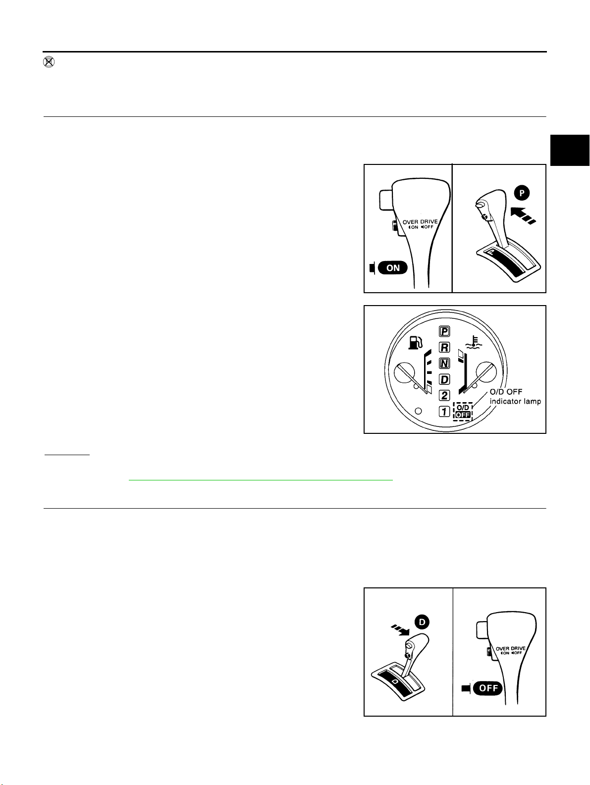
ON BOARD DIAGNOSTIC SYSTEM DESCRIPTION
TCM SELF-DIAGNOSTIC PROCEDURE (NO TOOLS)
[EURO-OBD]
A
1. CHECK O/D OFF INDICATOR LAMP
1. Start engine and warm it up to normal operating temperature.
2. Turn ignition switch to “OFF” position.
Wait 5 seconds.
3. Turn ignition switch to “ACC” position.
4. Set overdrive control switch to “ON” position.
5. Move selector lever to “P” position.
6. Turn ignition switch to “ON” position. (Do not start engine.)
7. Does O/D OFF indicator lamp come on for about 2 seconds?
B
AT
D
E
F
SAT774B
G
H
I
Yes or No
Yes >> GO TO 2
No >> Go to AT-23 2, "
1. O/D OFF Indicator Lamp Does Not Come On" .
2. JUDG EMENT PROCEDURE STEP 1
1. Turn ignition switch to “OFF” position.
2. Turn ignition switch to “ACC” position.
3. Move selector lever to “D” position.
4. Set overdrive control switch to “OFF” position.
5. Turn ignition switch to “ON” position. (Do not start engine.)
– Wait more than 2 seconds after turning ignition switch “ON”.
>> GO TO 3
SCIA0693E
SAT653E
J
K
L
M
AT-51
Page 56
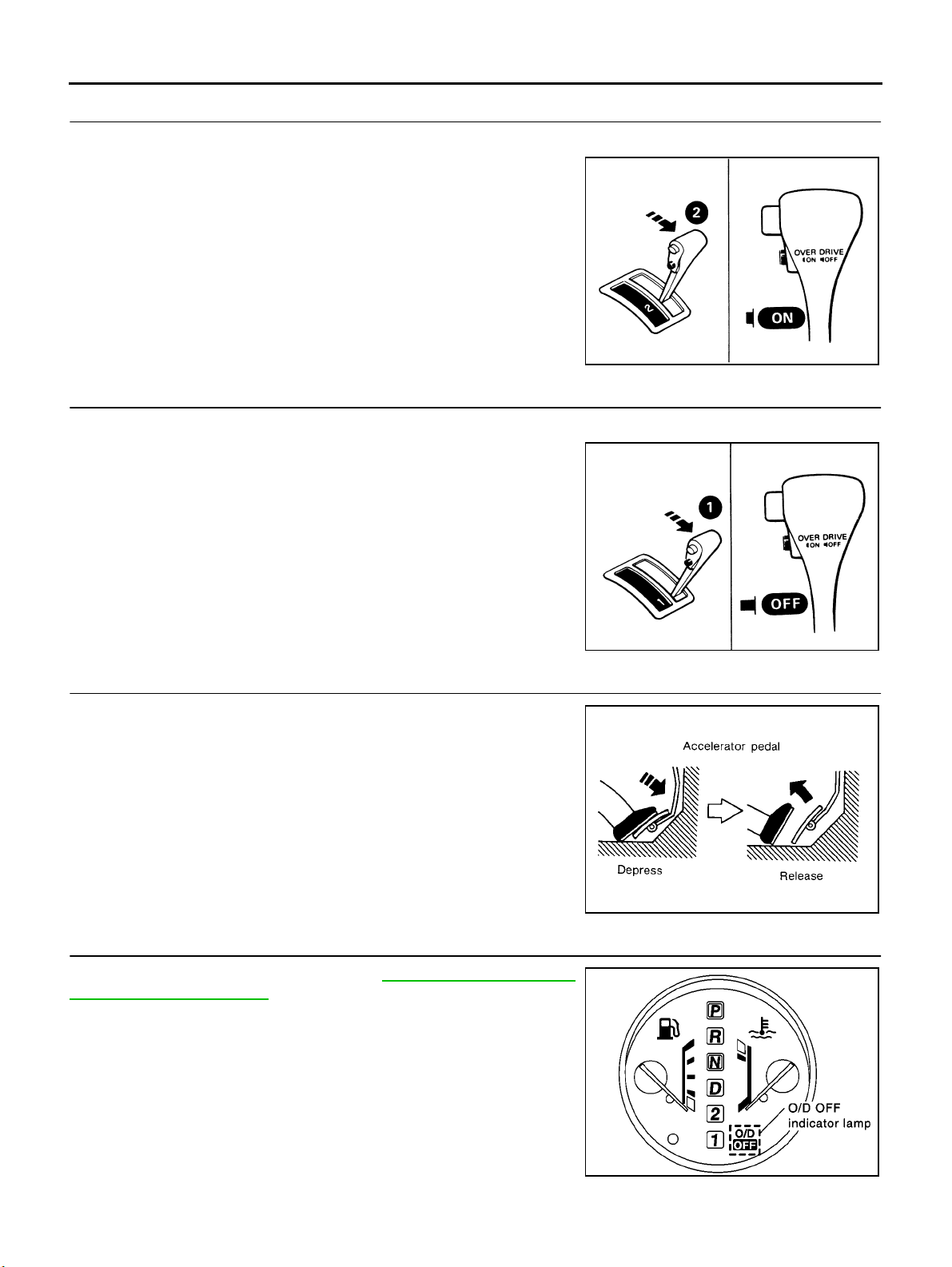
ON BOARD DIAGNOSTIC SYSTEM DESCRIPTION
3. JUDGEMENT PROCEDURE STEP 2
1. Move selector lever to “2” position.
2. Set overdrive control switch to “ON” position.
>> GO TO 4
4. JUDGEMENT PROCEDURE STEP 3
1. Move selector lever to “1” position.
2. Set overdrive control switch to “OFF” position.
>> GO TO 5
[EURO-OBD]
SAT780B
5. JUDGEMENT PROCEDURE STEP 4
1. Depress accelerator pedal fully and release it.
>> GO TO 6
6. CHECK SELF-DIAGNOSIS CODE
Check O/D OFF indicator lamp. Refer to AT-53, "
SELF-DIAGNOSIS CODE" .
>> DIAGNOSIS END
SAT781B
SAT981F
JUDGEMENT OF
AT-52
SCIA0693E
Page 57
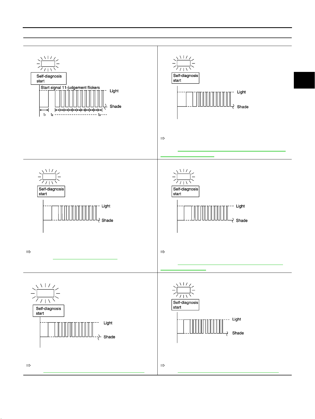
ON BOARD DIAGNOSTIC SYSTEM DESCRIPTION
JUDGEMENT OF SELF-DIAGNOSIS CODE
O/D OFF indicator lamp:
All judgement flickers are the same.
[EURO-OBD]
A
1st judgement flicker is longer than others.
B
AT
D
SCIA0694E SCIA0695E
All circuits that can be confirmed by self-diagnosis are OK.
2nd judgement flicker is longer than others.
SCIA0696E SCIA0697E
Vehicl e sp eed sensor circu it is shor t-c ircuit ed or disc onnected.
Go to VEHICLE SPEED SENSOR·MTR.
EURO-OBD: AT-22 1, "
4th judgement flicker is longer than others.
Component Inspection"
Revolution sensor circuit is short-circuited or disconnected.
Go to DTC P0720 VEHICLE SPEED SENSOR·A/T (REVOLU-
TION SENSOR).
Refer to AT-14 2, "
(REVOLUTION SENSOR)"
3rd judgement flicker is longer than others.
Throttle position sensor circuit is short-circuited or disconnected.
Go to DTC P1705 ACCELEPAT OR PEDAL POSI-
TION(APP)SENSOR
Refer to AT-20 3, "
TION (APP) SENSOR"
5th judgement flicker is longer than others.
DTC P0720 VEHICLE SPEED SENSOR·A/T
DTC P1705 ACCELERATOR PEDAL POSI-
E
F
G
H
I
J
K
L
SCIA0698E SCIA0699E
Shift solenoid valve A circuit is short-circuited or disconnected.
Go to DTC P0750 SHIFT SOLENOID VALVE A.
Refer to AT-19 3, "
DTC P0750 SHIFT SOLENOID VALVE A"
Shift solenoid valve B circuit is short-circuited or disconnected.
Go to DTC P0755 SHIFT SOLENOID VALVE B.
Refer to AT-19 8, "
DTC P0755 SHIFT SOLENOID VALVE B"
AT-53
M
Page 58
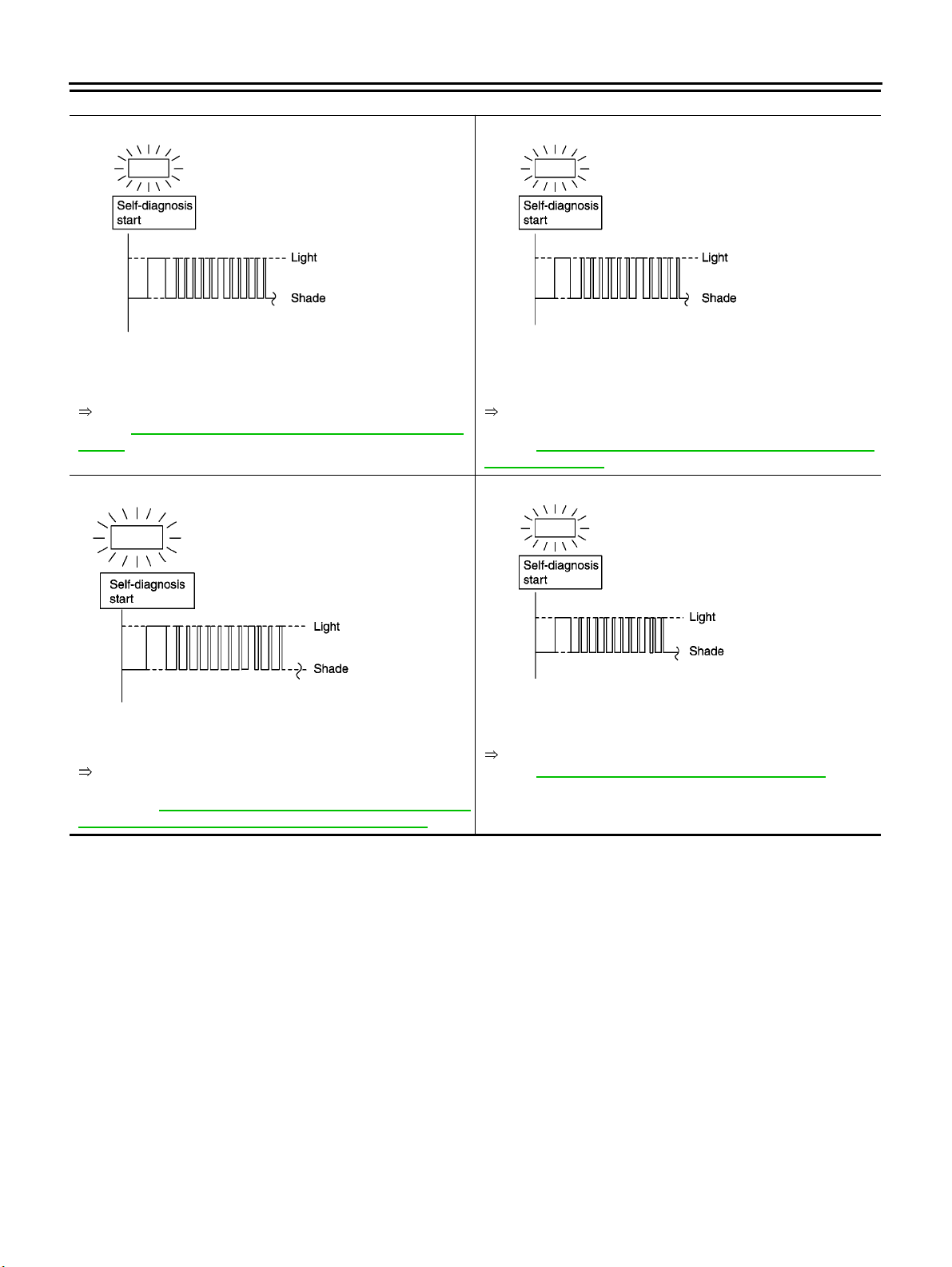
ON BOARD DIAGNOSTIC SYSTEM DESCRIPTION
6th judgement flicker is longer than others.
SCIA0700E SCIA0701E
[EURO-OBD]
O/D OFF indicator lamp:
7th judgement flicker is longer than others.
Overrun clutch solenoid valve circuit is short-circuited or disconnected.
Go to DTC P1760 OVERRUN CLUTCH SOLENOID VALVE.
Refer to AT-2 08, "
VALV E "
8th judgement flicker is longer than others.
A/T fluid temperature sensor is disconnected or TCM power
source circuit is damaged.
Go to DTC BATT/FLUID TEMP SEN A/T FLUID TEMP SEN-
SOR CIRCUIT AND TCM POWER SOURCE .
EURO-OBD: AT- 216, "
TEMP SENSOR CIRCUIT AND TCM POWER SOURCE)"
DTC P1760 OVERRUN CLUTCH SOLENOID
SCIA0702E SCIA0703E
DTC BATT/FLUID TEMP SEN (A/T FLUID
To r q u e conv e r t er cl u t c h s ole noid v a l ve cir c u i t is sh o r t- c ir c uite d o r
disconnected.
Go to DTC P0740 TORQUE CONVERTER CLUTCH SOLE-
NOID VALVE.
Refer to AT-1 8 1, "
SOLENOID VALVE"
9th judgement flicker is longer than others.
Engine speed signal circuit is short-circuited or disconnected.
Go to DTC P0725 ENGINE SPEED SIGNAL.
Refer to AT-1 4 7, "
DTC P0740 TORQUE CONVERTER CLUTCH
DTC P0725 ENGINE SPEED SIGNAL"
AT-54
Page 59
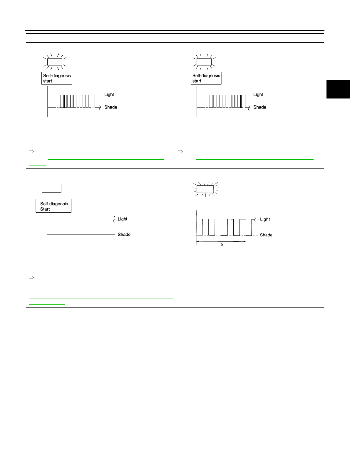
ON BOARD DIAGNOSTIC SYSTEM DESCRIPTION
[EURO-OBD]
O/D OFF indicator lamp:
10th judgement flicker is longer than others.
SCIA0704E SCIA0705E
Line pressure solenoid valve circuit is short-circuited or disconnected.
Go to DTC P0745 LINE PRESSURE SOLENOID VALVE.
Refer to AT-18 6, "
VALV E "
Lamp comes off.
DTC P0745 LINE PRESSURE SOLENOID
11th ju dgem ent fl icke r is longe r th an othe rs.
The ECM-AT communication line is open or shorted.
Go to DTC U1000 CAN COMMNICATION LINE.
Refer toEC-114, "
Flickers as shown below.
DTC U1000 CAN COMMUNICATION LINE"
A
B
AT
D
E
F
G
H
SCIA0706E SAT804H
PNP switch, overdrive control switch or throttle position switch circuit is disconnected or TCM is damaged.
Go to 21. TCM Self-diagnosis Does Not Activate (PNP and
OVERDRIVE CONTROL switches).
Refer to AT-26 0, "
(PNP & Overdrive C ontrol Switches, and Throttle Position Sensor
Circuit Checks)"
t1 =2.5seconds t2 =2.0seconds t3 =1.0second t4 =1.0second
21. TCM Self-diagnosis Does Not Activate
Battery power is low.
Battery has been disconnected for a long time.
Battery is connected conversely.
(When reconnecting TCM connectors.—This is not a problem).
I
J
K
L
M
AT-55
Page 60
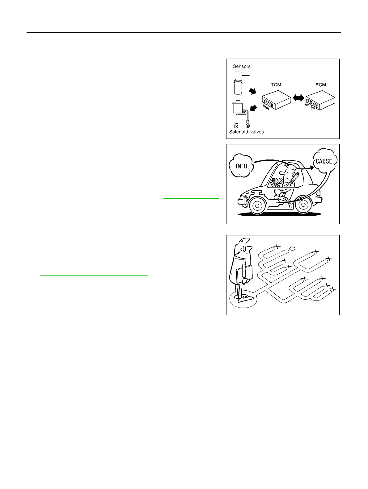
TROUBLE DIAGNOSIS — INTRODUCTION
[EURO-OBD]
TROUBLE DIAGNOSIS — INTRODUCTION
Introduction
The TCM receives a signal from the vehicle speed sensor, throttle
position sensor or PNP switch and provides shift control or lock-up
control via A/T solenoid valves.
The TCM also communicates with the EC M by means of a signal
sent from sensing elements used with the EURO-OBD related parts
of the A/T system for malfunction-diagnostic purposes. The TCM is
capable of diagnosing malfunctioning parts while the ECM can store
malfunctions in its memory.
Input and output signals must always be correct and stable in the
operation of the A/T system. The A/T system must be in good operating condition and be free of valve seizure, solenoid valve malfunction, etc.
It is much more difficult to diagnose a problem that occurs intermittently rather than continuously. Most intermittent problems are
caused by poor electric connections or improper wiring. In this case,
careful checking of suspected circuits may help prevent the replacement of good parts.
Avisualcheckonly,maynotfindthecauseoftheproblems.Aroad
test with CONSULT-II (or GST) or a circuit tester connected should
be performed. Follow the “Work Flow”. Refer to AT-61, "
Work Flow" .
PFP:00000
ECS0 04QO
SAT631IA
Before undertaking actual checks, take a few minutes to talk with a
customer who approaches with a driveability complaint. The customer can supply good information about such problems, especially
intermittent ones. Find out what symptoms are present and under
what conditions they occur. A “Diagnostic Worksheet” like the example (AT-5 7, "
DIAGNOSTIC WORKSHEET" )shouldbeused.
Start your diagnosis by looking for “conventional” problems first. This
will help troubleshoot driveability problems on an electronically controlled engine vehicle.
Also check related Service bulletins for information.
SAT632I
SEF234G
AT-56
Page 61
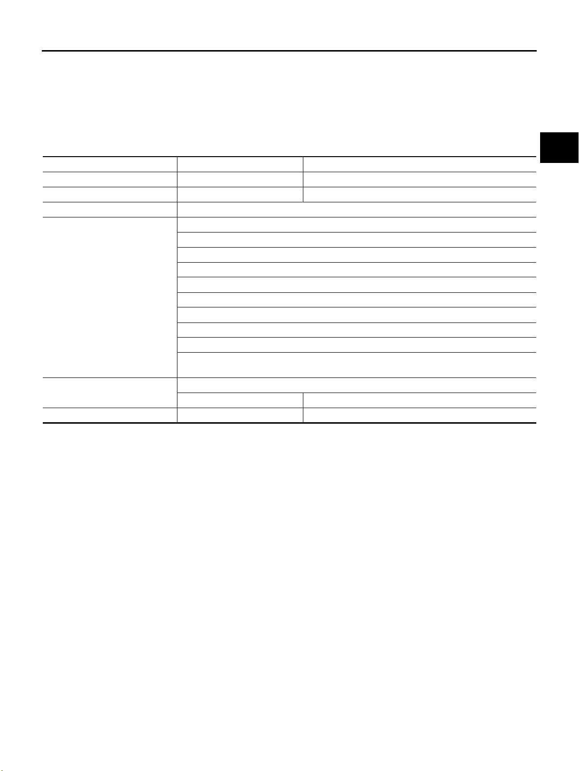
TROUBLE DIAGNOSIS — INTRODUCTION
DIAGNOSTIC WORKSHEET
Information from Customer
KEY POINTS
● WHAT ..... Vehicle & A/T model
● WHEN..... Date, Frequencies
● WHERE..... Road conditions
● HOW..... Operating conditions, Symptoms
Customer name MR/MS Model & Year VIN
Tran s. model Engine Mileage
Incident Date Manuf. Date In Service Date
Frequency ❏ Continuous ❏ Intermittent ( times a day)
Symptoms ❏ Vehicle does not move. (❏ Any position ❏ Particular position)
❏ No up-shift (❏ 1st → 2nd ❏ 2nd → 3rd ❏ 3rd → O/D)
❏ No down-shift (❏ O/D → 3rd ❏ 3rd → 2nd ❏ 2nd → 1st)
❏ Lockup malfunction
❏ Shift point too high or too low.
❏ Shift shock or slip (❏ N → D ❏ Lockup ❏ Any drive position)
❏ Noise or vibration
❏ No kickdown
❏ No pattern select
❏ Others
()
O/D OFF indicator lamp Blinks for about 8 seconds.
❏ Continuously lit ❏ Not lit
Malfunction indicator lamp (MIL) ❏ Continuously lit ❏ Not lit
[EURO-OBD]
A
B
AT
D
E
F
G
H
I
J
K
M
L
AT-57
Page 62
TROUBLE DIAGNOSIS — INTRODUCTION
[EURO-OBD]
Diagnostic Worksheet
1. ❏ Read the Fail-safe and listen to customer complaints. AT-57, "Infor-
mation from
Customer"
2. ❏ CHECK A/T FLUID AT-6 4 , "A/T
❏ Leakage (Follow specified procedure)
❏ Fluid condition
❏ Fluid level
3. ❏ Perform STALL TEST and LINE PRESSURE TEST. AT-6 5 , "
❏ Stall test — Mark po ssible dama ged components/o thers.
❏ Torque co n v e r t e r one-way cl u t c h
❏ Reverse clutch
❏ Forward clutch
❏ Overrun clutch
❏ Forward one-way clutch
❏ Line Pressure test — Suspected parts:
❏ Low & reverse brake
❏ Low one-way clutch
❏ Engine
❏ Line pressure is low
❏ Clutches and brakes except high clutch and
brake band are OK
Fluid Check"
Stall
Test", AT-6 8,
"Line Pressure Test"
AT-58
Page 63

TROUBLE DIAGNOSIS — INTRODUCTION
[EURO-OBD]
4. ❏ Perform all ROAD TEST and mark required procedures. AT-6 9 , "Road
Test"
4-1.Check before engine is started. AT-7 0 , "1.
❏ SELF-DIAGNOSTIC PROCEDURE/DIAGNOSTIC TROUBLE CODE (DTC) CONFIRMATION PROCEDURE. — Mark detected items.
❏ PNP switch, AT-130, "
❏ A/T fluid temperature sensor, AT-136, "
CUIT" .
❏ Vehicle speed sensor·A/T (Revolution sensor), AT-142 , "
SOR·A/T (REVOLUTION SENSOR)" .
❏ Engine speed signal, AT-147 , "
❏ Torque con ver ter cl u t c h s o l e noid val v e , AT-18 1, "
SOLENOID VALVE" .
❏ Line pressure solenoid valve, AT-1 86, "
❏ Shift solenoid valve A, AT-193, "
❏ Shift solenoid valve B, AT-198, "
❏ Accelerator pedal position (App) sensor, AT-203 , "
(APP) SENSOR" .
❏ Overrun clutch solenoid valve, AT- 208 , "
❏ PNP & overdrive control switches, and throttle position sensor, AT-2 60, "
Does Not Activate (PNP & Overdrive Control Switches, and Throttle Position Sensor Circuit Checks)"
.
❏ Batt/fluid temp sen (A/T fluid temperature sensor and TCM power source), AT-2 1 6, "
FLUID TEMP SEN (A/T FLUID TEMP SENSOR CIRCUIT AND TCM POWER SOURCE)" .
❏ Vehicle speed sensor·MTR, AT- 222, "
❏ CAN communication line, EC-114, "
❏ Control unit (RAM), control unit (ROM), AT-226 , "
(ROM)" .
❏ Control unit (EEP ROM), AT-228, "
❏ Battery
❏ Others
4-2.Check at idle AT-7 1 , "
❏ 1. O/D OFF Indicator Lamp Does Not Come On, AT-2 32, "1. O/D OFF Indicator Lamp Does Not Come
On" .
❏ 2. Engine Cannot Be Started In “P” And “N” Position, AT-233 , "
“N” Position" .
❏ 3. In “P” Position, Vehicle Moves Forward Or Backward When Pushed, AT-234, "
cle Moves Forward Or Backward When Pushed" .
❏ 4. In “N” Position, Vehicle Moves, AT-2 34, "
❏ 5. Large Shock. “N” → “R” Position, AT- 236 , "
❏ 6. Vehicle Does Not Creep Backward In “R” Position, AT-2 37, "
“R” Position" .
❏ 7. Vehicle Does Not Creep Forward In “D”, “2” Or “1” Position, AT-2 40, "
ward In “D”, “2” Or “1” Position" .
DTC P0705 PARK/NEUTRAL POSITION (PNP) SWITCH" .
DTC P0710 A/T FLUID TEMPERATURE SENSOR CIR-
DTC P0720 VEHICLE SPEED SEN-
DTC P0725 ENGINE SPEED SIGNAL" .
DTC P0740 TORQUE CONVERTER CLUTCH
DTC P0745 LINE PRESSURE SOLENOID VALVE" .
DTC P0750 SHIFT SOLENOID VALVE A" .
DTC P0755 SHIFT SOLENOID VALVE B" .
DTC P1705 ACCELERATOR PEDAL POSITION
DTC P1760 OVERRUN CLUTCH SOLENOID VALVE" .
21. TCM Self-diagnosis
DTC BATT/
DTC VEHICLE SPEED SENSOR MTR" .
DTC U1000 CAN COMMUNICATION LINE" .
DTC CONTROL UNIT (RAM), CONTROL UNIT
DTC CONTROL UNIT(EEPROM)" .
2. Engine Cannot Be Started In “P” and
3. In “P” Position, Vehi-
4. In “N” Position, Vehicle Moves" .
5. Large Shock. “N” → “R” Position" .
6. Vehicle Does Not Creep Backward In
7. Vehicle Does Not Creep For-
CHECK
BEFORE
ENGINE IS
STARTED"
2.
CHECK AT
IDLE"
A
B
AT
D
E
F
G
H
I
J
K
L
M
AT-59
Page 64
TROUBLE DIAGNOSIS — INTRODUCTION
[EURO-OBD]
4. 4-3.Cruise test AT-7 4 , "3.
Part-1
❏ 8. Vehicle Cannot Be Started From D
❏ 9. A/T Does Not Shift: D
1 → D2 Or Does Not Kickdown: D4 → D2 , AT-24 4, "9. A/T Does Not Shift: D1
1 , AT-242, "8. Vehicle Cannot Be Started From D1" .
→ D2 Or Does Not Kickdown: D4 → D2" .
❏ 10. A/T Does Not Shift: D
❏ 11. A/T Does Not Shi ft: D
❏ 12. A/T Does Not Perform Lock-up, AT-252, "
❏ 13. A/T Does Not Hold Lock-up Condition, AT-253 , "
❏ 14. Lock-up Is Not Released, AT-25 4, "
❏ 15. Engine Speed Does Not Return To Idle (Light Braking D
2 → D3 , AT-246, "10. A/T Does Not Shift: D2 → D3" .
3 → D4 , AT-249, "11. A/ T Does Not Shift: D3 → D4" .
12. A/T Does Not Perform Lock-up" .
13. A/T Does Not Hold Lock-up Condition" .
14. Lock-up Is Not Released" .
4 → D3 ), AT-2 55, "15. Engine Speed Does
Not Return To Idle (Light Braking D4 → D3 )" .
Part-2 AT-8 1 ,
❏ 16. Vehicle Does Not Start From D1 , AT-257, "16. Vehicle Does Not St art From D 1" .
❏ 9. A/T Does Not Shift: D
1 → D2 Or Does Not Kickdown: D4 → D2 , AT-24 4, "9. A/T Does Not Shift: D1
→ D2 Or Does Not Kickdown: D4 → D2" .
❏ 10. A/T Does Not Shift: D
❏ 11. A/T Does Not Shi ft: D
2 → D3 , AT-246, "10. A/T Does Not Shift: D2 → D3" .
3 → D4 , AT-249, "11. A/ T Does Not Shift: D3 → D4" .
Part-3 AT-8 3 ,
❏ 17. A/T Does Not Shift: D4 → D3 When Overdrive Control Switch “ON” → “OFF”, AT-2 58 , "17. A/T Does
Not Shift: D4 → D3 ,WhenOverdriveControlSwitch“ON” → “OFF”" .
❏ 15. Engine Speed Does Not Return To Idle (Engine Brake In D
3 ), AT-255 , "15. Engine Speed Does Not
Return To Idle (Light Braking D4 → D3 )" .
❏ 18. A/T Does Not Shift: D
3 → 22 ,WhenSelectorLever“D”→ “2” Position, AT-258 , "18. A/T Does Not
Shift: D3 → 22 ,WhenSelectorLever“D” → “2” Position" .
❏ 15. Engine Speed Does Not Re turn To Idle (Engine Brake In 2
2 ), AT-255 , "15. Engine Speed Does Not
Return To Idle (Light Braking D4 → D3 )" .
❏ 19. A/T Does Not Shift: 2
2 → 11 ,WhenSelectorLever“2”→ “1” Position, AT-259 , "19. A/T Does Not
Shift: 22 → 11 ,WhenSelectorLever“2” → “1” Position" .
❏ 20. Vehicle Does Not Decelerate By Engine Brake, AT- 259 , "
20. Vehicle Does Not Decelerate By Engine
Brake" .
❏ 21. TCM Self-diagnosis Does Not Activate (PNP & Overdrive control switches, and throttle position sensor circuit checks), AT-260, "
21. TCM Self-diagnosis Does Not Activate (PNP & Overdrive Control
Switches, and Throttle Position Sensor Circuit Checks)" .
❏ SELF-DIAGNOSTIC PROCEDURE/DIAGNOSTIC TROUBLE CODE (DTC) CONFIRMATION PROCEDURE — Mark detected items.
❏ PNP switch, AT-1 30, "
❏ A/T fluid temperature sensor, AT-1 36 , "
DTC P0705 PARK/NEUTRAL POSITION (PNP) SWITCH" .
DTC P0710 A/T FLUID TEMPERATURE SENSOR CIRCUIT" .
❏ Vehicle speed sensor·A/T (Revolution sensor), AT- 142, "
DTC P0720 VEHICLE SPEED SEN-
SOR·A/T (REVOLUTION SENSOR)" .
❏ Engine speed signal, AT-147 , "
❏ Torque co n verter cl u t c h so l enoid v a l v e , AT-1 81, "
DTC P0725 ENGINE SPEED SIGNAL" .
DTC P0740 TORQUE CONVERTER CLUTCH
SOLENOID VALVE" .
❏ Line pressure solenoid valve, AT-1 86, "
❏ Shift solenoid valve A, AT-193, "
❏ Shift solenoid valve B, AT-198, "
❏ Accelerator pedal position (App) sensor, AT-203, "
DTC P0745 LINE PRESSURE SOLENOID VALVE" .
DTC P0750 SHIFT SOLENOID VALVE A" .
DTC P0755 SHIFT SOLENOID VALVE B" .
DTC P1705 ACCELERATOR PEDAL POSITION
(APP) SENSOR" .
❏ Overrun clutch solenoid valve, AT- 208, "
❏ PNP & overdrive control switches, and throttle position sentor, AT-260 , "
DTC P1760 OVERRUN CLUTCH SOLENOID VALVE" .
21. TCM Self-diagnosis
Does Not Activate (PNP & Overdrive Control Switches, and Throttle Position Sensor Circuit Checks)"
.
❏ A/T fluid temperature sensor and TCM power source, AT-216, "
DTC BATT/FLUID TEMP SEN (A/T
FLUID TEMP SENSOR CIRCUIT AND TCM POWER SOURCE)" .
❏ Vehicle speed sensor·MTR, AT-222, "
❏ CAN communication line, EC-114, "
❏ Control unit (RAM), control unit (ROM), AT-226, "
DTC VEHICLE SPEED SENSOR MTR" .
DTC U1000 CAN COMMUNICATION LINE" .
DTC CONTROL UNIT (RAM), CONTROL UNIT
(ROM)" .
❏ Control unit (EEP ROM), AT-228, "
DTC CONTROL UNIT(EEPROM)" .
❏ Battery
❏ Others
CRUISE
TEST"
AT-7 8 ,
"Cruise Test
— Part 1"
"Cruise Test
— Part 2"
"Cruise Test
— Part 3"
AT-60
Page 65
TROUBLE DIAGNOSIS — INTRODUCTION
[EURO-OBD]
5. ❏ For self-diagnosis NG items, inspect each component. Repair or replace the damaged parts. AT-5 0 , "Diag-
nostic Procedure Without
CONSULT-II"
6. ❏ Perform all ROAD TEST and re-mark required procedures. AT-6 9 , "Road
Test"
7. ❏ Perform DTC CONFIRMATION PROCEDURE for following MIL indicating items and check out NG items.
Refer to "EC-XX", “Emission-related Diagnostic Information”.
❏ DTC (P0731) A/T 1st gear function, AT-151, "
❏ DTC (P0732) A/T 2nd gear function, AT-1 58, "
❏ DTC (P0733) A/T 3rd gear function, AT-165, "
❏ DTC (P0734) A/T 4th gear function, AT-172, "
8. ❏ Perform the Diagnostic Procedures for all remaining items marked NG. Repair or replace the damaged parts.
Refer to the Symptom Chart when you perform the procedures. (The chart also shows some other possible
symptoms and the component inspection orders.)
9. ❏ Erase DTC from TCM and ECM memories. AT-3 9 , "HOW
DTC P0731 A/T 1ST GEAR FUNCTION" .
DTC P0732 A/T 2ND GEAR FUNCTION" .
DTC P0733 A/T 3RD GEAR FUNCTION" .
DTC P0734 A/T 4TH GEAR FUNCTION" .
Work Flow
EC section
AT-8 6 ,
"Symptom
Chart"
TO ERASE
DTC"
ECS004QP
HOW TO PERFORM TROUBLE DIAGNOSES FOR QUICK AND ACCURATE REPAIR
Agoodunderstandingofthemalfunctionconditionscanmaketroubleshootingfasterandmoreaccurate.In
general, each customer feels differently about a problem. It is important to fully understand the symptoms or
conditions for a customer complaint.
Make good use of the two sheets provided, “INFORMATION FROM CUSTOMER” (AT-57, "
Customer" )and“DIAGNOSTICWORKSHEET”(AT-58 , "Diagnostic Worksheet" ), to perform the best trouble-
shooting possible.
Information from
A
B
AT
D
E
F
G
H
K
M
I
J
L
AT-61
Page 66
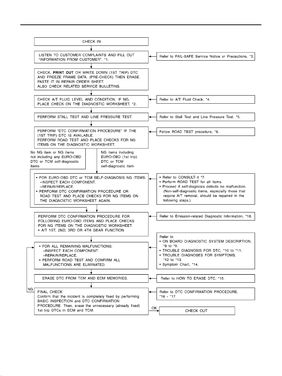
WORK FLOW CHART
TROUBLE DIAGNOSIS — INTRODUCTION
[EURO-OBD]
AT-62
SAT183K
Page 67

TROUBLE DIAGNOSIS — INTRODUCTION
[EURO-OBD]
*1: AT-5 7, "Information from Customer" *2: AT-5 8, "Diagnostic Worksheet" *3: AT-7, "Service Notice or Precau-
tions"
*4: AT-6 4, "A/T Fluid Check" *5: AT-6 5, "Stall T est" and AT-68 , "Line Pressure
Te s t "
*7: AT-4 1, "CONSULT-II" *8: AT- 3 7, "ON BOARD DIAGNOSTIC SYSTEM
DESCRIPTION"
*10: AT-1 30, "DTC P0705 PARK/NEU-
TRAL POSITION (PNP) SWITCH"
*13: AT-2 59, "20. Vehicle Does Not Decel-
erate By Engine Brake"
*16: AT-1 31, "DIAGNOSTIC TROUBLE
CODE (DTC) CONFIRMATION PROCEDURE"
*11: AT- 222 , "DTC VEHICLE SPEED SENSOR
MTR" and AT- 226 , "DTC CONTROL UNIT
(RAM), CONTROL UNIT (ROM)" to AT-2 28,
"DTC CONTROL UNIT(EEPROM)"
*14: AT-8 6, "Symptom Chart" *15: AT-3 9, "HOW TO ERASE DTC"
*17: AT-2 22, "DTC VEHICLE SPEED SENSOR
MTR" and AT- 226 , "DTC CONTROL UNIT
(RAM), CONTROL UNIT (ROM)" to AT-2 28,
"DTC CONTROL UNIT(EEPROM)"
*6: AT-6 9, "Road Test"
*9: AT-5 0, "Diagnostic Procedure
Without CONSULT-II"
*12: AT-232 , "1. O/D OFF Indicator
Lamp Does Not Come On"
*18: EC-XX
A
B
AT
D
E
F
G
H
K
M
I
J
L
AT-63
Page 68
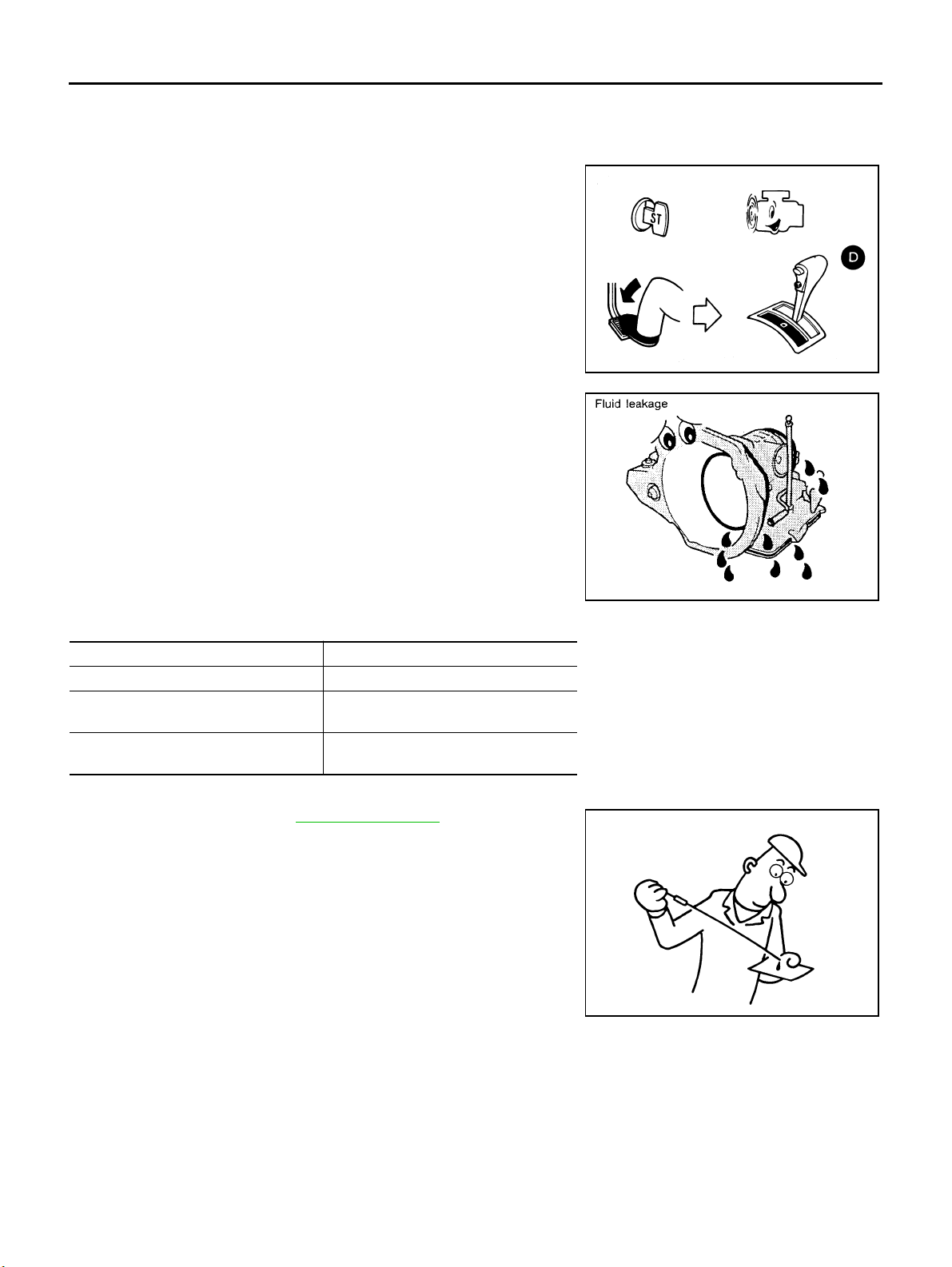
TROUBLE DIAGNOSIS — BASIC INSPECTION
[EURO-OBD]
TROUBLE DIAGNOSIS — BASIC INSPECTION
A/T Fluid Check
FLUID LEA KAGE CHECK
1. Clean area suspected of leaking. — for example, mating surface
of converter housing and transmission case.
2. Start engine, apply foot brake, place selector lever in “D” position and wait a few minutes.
3. Stop engine.
4. Check for fresh leak age.
PFP:00000
ECS0 04QQ
SAT767B
FLUID CONDITION CHECK
Fluid color Suspected problem
Dark or black with burned odor Wear of frictional material
Milky pink Water contamination — Road water
entering through filler tube or breather
Var nis hed fluid , li gh t to da r k brow n and
tacky
Oxidation — Over or under filling, —
Overheating
FLUID LEVEL CHECK
Refer to “Checking A/T Fluid”, AT-13, " A/T FLUID" .
SAT288G
SAT638A
AT-64
Page 69
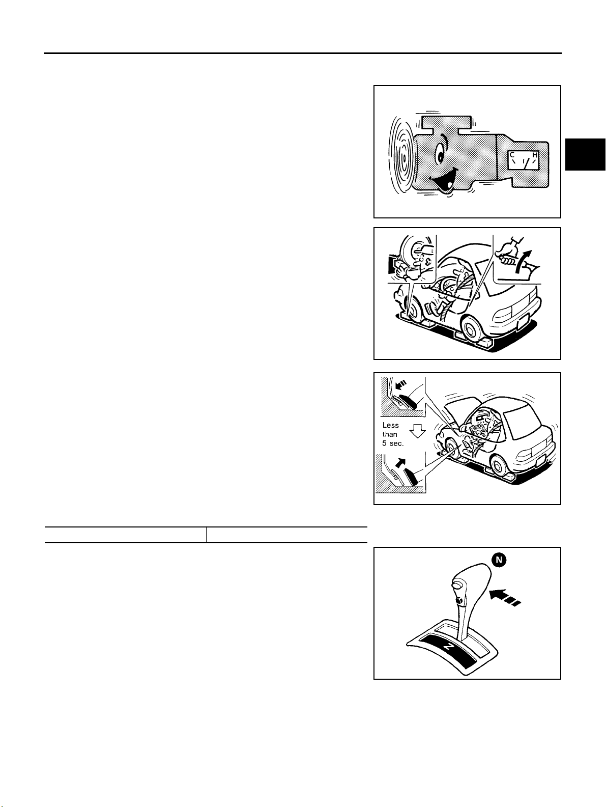
TROUBLE DIAGNOSIS — BASIC INSPECTION
[EURO-OBD]
Stall Test
STALL TEST PROCEDURE
1. Check A/T fluid and engine oil levels. If necessary, add.
2. Drive vehicle for approx. 10 minutes or until fluid and oil reach
operating temperature.
ATF operating tempera ture:
50 - 80°C(122-176°F)
3. Set parking brake and block wheels.
4. Install a tachometer where it can be seen by driver during test.
● It is good practice to mark the point of specified engine
rpm on indicator.
ECS004QR
SAT647B
SAT513G
A
B
AT
D
E
F
G
H
5. Start engine, apply foot brake, and place selector lever in D
position.
6. Accelerate to wide open throttle gradually while applying foot
brake.
7. Quickly note the engine stall revolution and immediately release
throttle.
● During test, never hold throttle wide open for less than 5
seconds.
Stall revolution:
QR20DE 2,450 - 2,950 rpm
8. Move selector lever to “N” position.
9. Cool off ATF.
● Run engine at idle for at least one minute.
10. Repeat steps 5 through 9 with selector lever in “2”, “1” and “R”
positions.
I
J
K
SAT514G
L
M
AT-65
SAT771B
Page 70

TROUBLE DIAGNOSIS — BASIC INSPECTION
[EURO-OBD]
JUDGEMENT OF STALL TEST
The test result and possible damaged components relating to each result are shown in the illustrations on next
page.
In order to pinpoint the possible damaged components, follow the WORK FL OW shown in AT-284, "Work
Flow" (EXCEPT FOR EURO-OBD) or AT-61, "Work Flow" (EURO-OBD).
NOTE:
Stall revolution is too high in “D”, “2” or “1” position:
● Slippage occurs in 1st gear but not in 2nd and 3rd gears. ..... Low one-way clutch sl ippage
● Slippage occurs in the following gears:
1st through 3rd gears i n “D” position and engine brake functions with overdrive control switch set to
“OFF”.
1st and 2nd gears in “ 2” position and engine brake functions with accelerator pedal released (fully closed
throttle). ..... Forward clutch or forward one-way clutch slippage
Stall revolution is too high in R position:
● Engine brake does not function in “1” position. ..... Low & reverse brake slippage
● Engine brake functions in “1” position. ..... Reverse clutch slippage
Stall revolution within specifications:
● Vehi cle does no t a chieve speed of mor e than 80 k m/h (50 MPH). ..... One-w ay clutch s eizu re i n torque
converter housing
CAUTION:
Be careful since automatic fluid temperature increases abnormally.
● Slippage occurs in 3rd and 4th gears in “ D” position. ..... High clutch slippage
● Slippage occurs in 2nd and 4th gear in “D” position. ..... Brake band slippage
● Engine brake does not function in 2nd and 3rd gears i n “D” position, 2nd gear in “2” position, and 1st gear
in “1” position with overdrive control switch set to “OFF”.
Stall revolution less than specifications:
● Poor acceleration during starts. ..... One-way clutch seizure in t orque c onverter
AT-66
Page 71
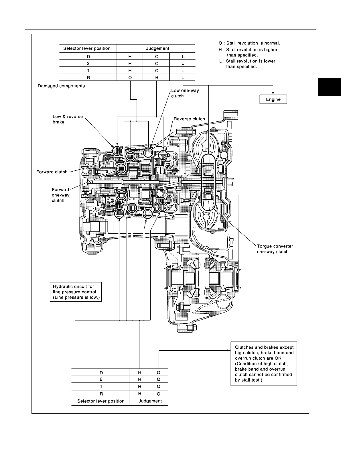
TROUBLE DIAGNOSIS — BASIC INSPECTION
[EURO-OBD]
A
B
AT
D
E
F
G
H
K
M
I
J
L
AT-67
SCIA0707E
Page 72
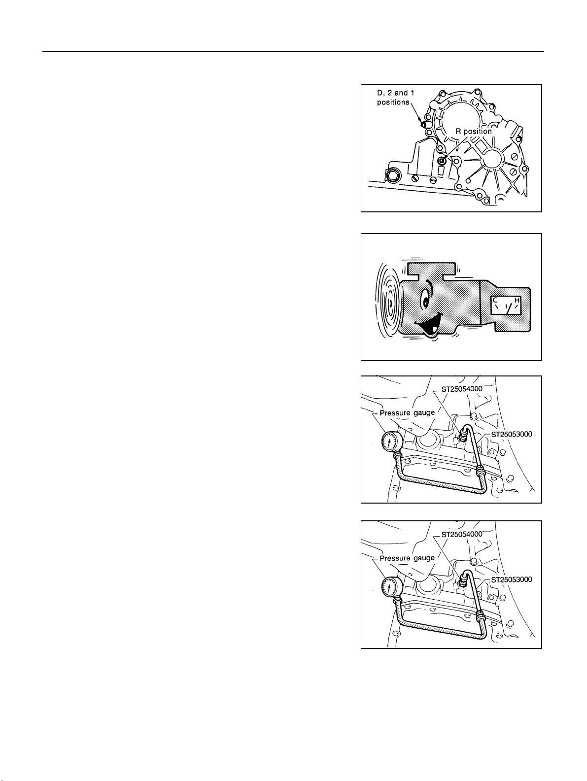
TROUBLE DIAGNOSIS — BASIC INSPECTION
[EURO-OBD]
Line Pressure Test
LINE PRESSURE TEST PORTS
Location of line pressure test ports are shown in the illustration.
● Always replace pressure plugs as they are self-se aling
bolts.
LINE PRESSURE TEST PRO CEDURE
1. Check A/T fluid and engine oil levels. If ne cessary, add fluid or
oil.
2. Drive vehicle fo r approx. 10 minutes or until engine oil and ATF
reach operating temperature.
ATF operatin g temper ature: 50 - 80°C(122-176°F)
ECS004QS
SCIA0709E
3. Install pressure gauge to corresponding line pressure port.
4. Set parking brake and block wheels.
● Continue to depress brake pedal fully while line pressure
test is being performed at stall speed.
SAT647B
UAT008
AT-68
UAT008
Page 73
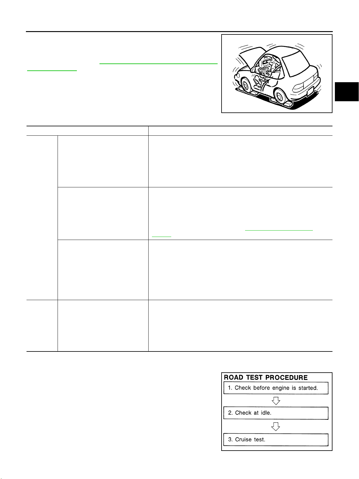
TROUBLE DIAGNOSIS — BASIC INSPECTION
5. Start engine and measure line pressure at idle and stall speed.
● When measuring line pressure at stall speed, follow the
stall test procedure.
Line pressure: Refer to AT-563, "
CATIONS (SDS)" .
JUDGEMENT OF LINE PRESSURE TEST
Judgement Suspected parts
Line pressure is low in all positions.
Line pressure is low in particular position.
At idle
Line pressure is high.
Line pressure is low.
At stall
speed
SERVICE DATA AND SPECIFI-
● Oil pump wear
● Control piston damage
● Pressure regulator valve or plug sticking
● Spring for pressure regulator valve damaged
● Fluid pressure leakage between oil strainer and pressure regulator valve
● Clogged strainer
● Fluid pressure leakage between manual valve and particular clutch
● For example, line pressure is:
− Low in “R” and “1” positions, but
− Normal in “D” and “2” positions.
Therefore, fluid leakage exists at or around low and reverse brake circuit.
Refer to “CLUTCH AND BAND CHART”, AT-19, " CLUTCH AND BAND
CHART" .
● Maladjustment of throttle position sensor
● A/T fluid temperature sensor damaged
● Line pressure solenoid valve sticking
● Short circuit of line pressure solenoid valve circuit
● Pressure modifier valve sticking
● Pressure regulator valve or plug sticking
● Open in dropping resistor circuit
● Maladjustment of throttle position sensor
● Line pressure solenoid valve sticking
● Short circuit of line pressure solenoid valve circuit
● Pressure regulator valve or plug sticking
● Pressure modifier valve sticking
● Pilot valve sticking
[EURO-OBD]
A
B
AT
SAT493G
D
E
F
G
H
I
J
K
L
M
Road Test
DESCRIPTION
● The purpose of the test is to determine overall performance of A/
Tandanalyzecausesofproblems.
● The road test consists of the following three parts:
1. Check before engine is started
2. Check at idle
AT-69
ECS004QT
SAT786A
Page 74
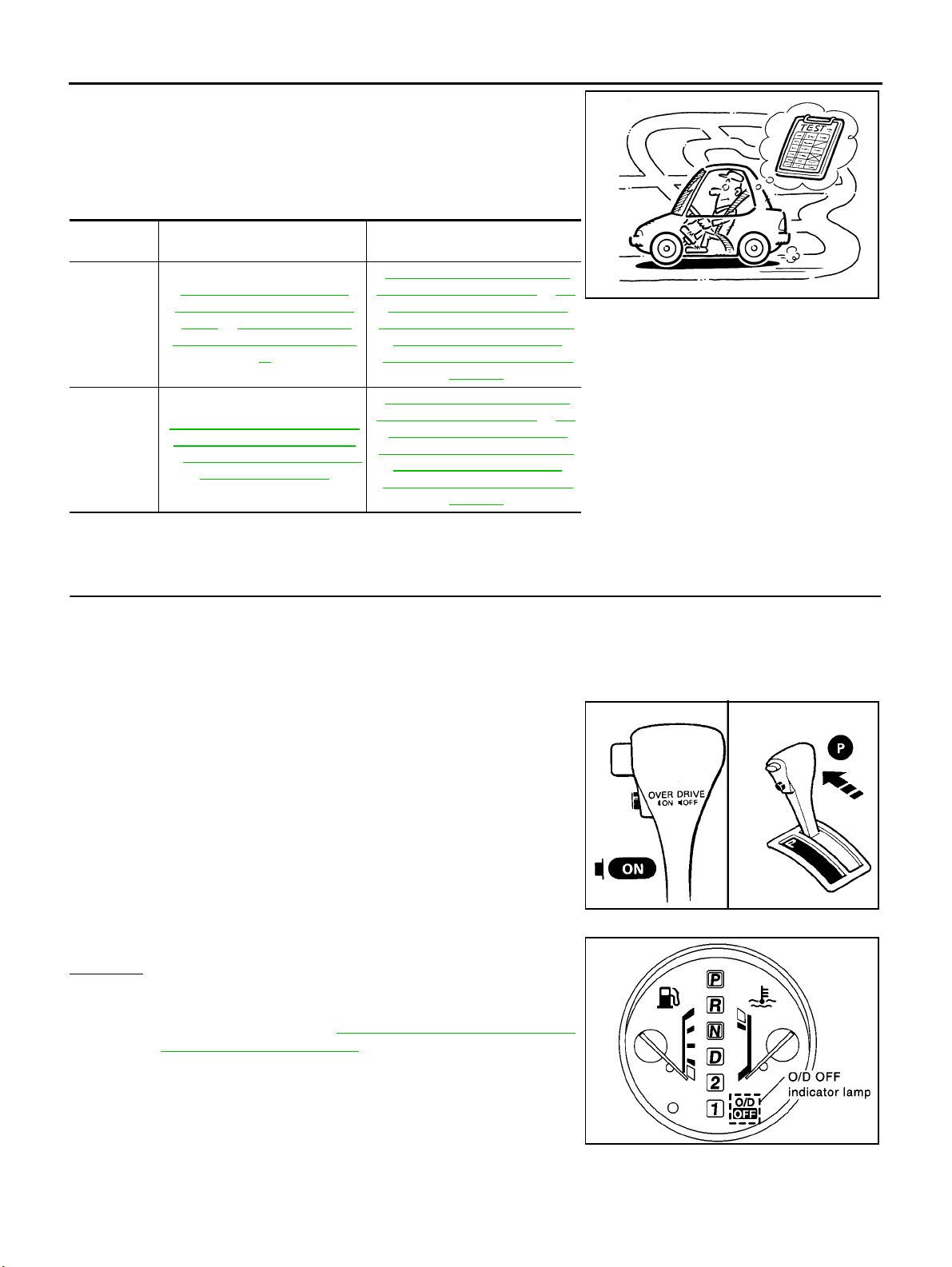
TROUBLE DIAGNOSIS — BASIC INSPECTION
3. Cruise test
● Before road test, familiarize yourself with all test procedures and
items to check.
● Conduct tests on all items until speci fied symptom i s fo und.
Troubleshoot items which check out No Good after road test.
Refer to the following items.
[EURO-OBD]
Except for
Euro-OBD
EURO-OBD
ON BOARD DIAGNOSITC SYS-
TEM DESCRIPTION
AT-26 7, "
NOSTIC SYSTEM DESCRIP-
TION" to AT-5 0, "Diagnostic
Procedure Without CONSULT-
AT-3 7, "
TIC SYSTEM DESCRIPTION"
to AT-5 0, "Diagnostic Procedure
ON BOARD DIAG-
II"
ON BOARD DIAGNOS-
Without CONSULT-II"
TROUBLE DIAGNOSES FOR
SYMPTOMS
AT-2 32, " 1. O/D OFF Indicator
Lamp Does Not Come On" to AT-
260, "21. TCM Self-diagnosis
Does Not Activate (PNP & Over-
drive Control Switches, and
Throttle Position Sensor Circuit
Checks)"
AT-2 32, " 1. O/D OFF Indicator
Lamp Does Not Come On" to AT-
260, "21. TCM Self-diagnosis
Does Not Activate (PNP & Over-
drive Control Switches, and
Throttle Position Sensor Circuit
Checks)"
1. CHECK BEFORE ENGINE IS STARTED
1. CHECK O/D OFF INDICATOR LAMP
1. Park vehicle on flat surface.
2. Turn ignition switch to “OFF” posit ion.
3. Move selector lever to “P ” position.
4. Set overdrive control switch to "ON" position.
5. Turn ignition switch to “ON” positio n. (Do not start engine.)
SAT496G
6. Does O/D O FF indicator lamp come on for about 2 seconds?
Yes o r No
Yes >> G O TO 2
No >> Stop ROAD TEST. Go to “1. O/D OFF Indicator Lamp
Does Not Come On”, AT- 2 3 2, "
1. O/D OFF Indicator
Lamp Does Not Come On" .
AT-70
SAT774B
SCIA0693E
Page 75
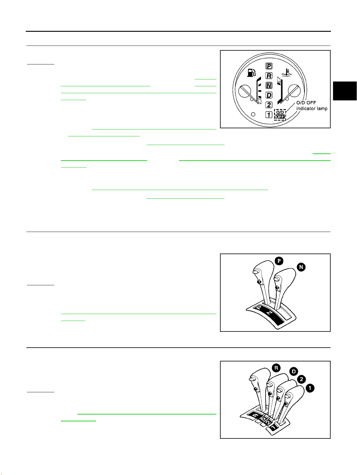
TROUBLE DIAGNOSIS — BASIC INSPECTION
[EURO-OBD]
2. CHECK O/D OFF INDICATOR LAMP
Does O/D OFF indicator lamp flicker for about 8 seconds?
Yes or No
Yes ( Exc e p t for Euro-OB D )>>Per f o r m self-di a g n os is a n d check
NG items on the DIAGNOSTIC WORKSHEET, AT- 280,
"DIAGNOSTIC WORKSHEET" .RefertoAT-273 ,
"SELF-DIAGNOSTIC PR OCED UR E (WITHOUT C O NSULT-II)" .
No (Except for Euro-OBD)>>1.Turn ignition switch to “OFF” posi-
tion.
2. Perform self-diagnosis and note NG items.
Refer to AT-27 3, "
(WITHOUT CONSULT-II)" .
3. Go to “2. CHECK AT IDLE”, AT-71, "
Yes ( EUR O -OBD ) > >Pe r f o rm self-diag n o s i s and ch e c k NG i t e m s on the DIAGNO S T I C WORKSH E E T, AT- 57,
"DIAGNOSTIC WORKSHEET" .RefertoAT-51 , " TCM SELF-DIAGNOSTIC PROCEDURE (NO
TOOLS)" .
No (EURO-OBD)>>1.Turn ignition switch to “OFF” position.
2. Perform self-diagnosis and note NG items.
Refer to AT-5 1, "
3. Go to “2. CHECK AT IDLE”, AT-71, "
SELF-DIAGNOSTIC PROCEDURE
2. CHECK AT IDLE" .
TCM SELF-DIAGNOSTIC PROCEDURE (NO TOOLS)" .
2. CHECK AT IDLE" .
2. CHECK AT IDLE
SCIA0693E
A
B
AT
D
E
F
G
H
1. CHECK ENGINE START
1. Park vehicle on flat surface.
2. Turn ignition switch to “OFF” position.
3. Move selector lever to “P” or “N” position.
4. Turn ignition switch to “START” position.
5. Is engine started?
Yes or No
Yes >> GO TO 2
No >> Mark the box on the DIAGNOSTIC WORKSHEET.Go to
"2 Engine Cannot Be Started In “P” and “N” Position”,
AT-2 3 3, "
Position" .ContinueROADTEST.
2. Engine Cannot Be Started In “P” and “N”
2. CHECK ENGINE START
1. Turn ignition switch to “OFF” position.
2. Move selector lever to “D”, “1”, “2” or “R” position.
3. Turn ignition switch to “START” position.
4. Is engine started?
Yes or No
Yes >> Mark the bo x on the D I A G NO ST I C WOR K S H E ET. Go
To " 2. E n gi ne C a nn o t B e Sta rte d I n “ P” a nd “ N” P os ition”, AT-233, "2. Engine Cannot Be Started In “P” and
“N” Position" .ContinueROADTEST.
No >> GO TO 3
SAT769B
SAT770B
I
J
K
L
M
AT-71
Page 76
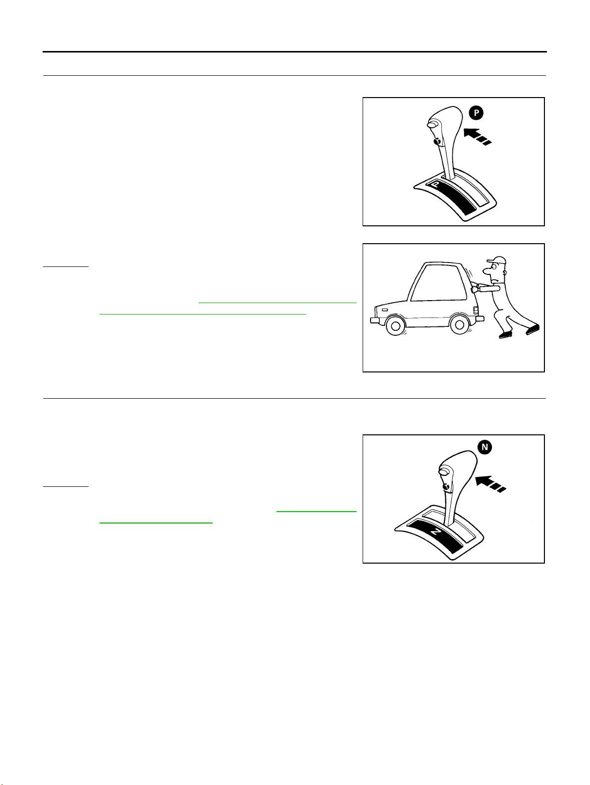
TROUBLE DIAGNOSIS — BASIC INSPECTION
3. CHECK VEHICLE MOVE
1. Turn ignition switch to “OFF” posit ion.
2. Move selector lever to “P ” position.
3. Release parking brake.
4. Push vehicle forward or backward.
5. Does vehicle move when it is pushed forward or backward?
Yes o r No
Yes >> M a r k th e box o n t h e D I A G N OS T I C W O R K SH E E T. Go
To " 3. In “ P” P o si t io n, Vehic l e Mo v e s For w ar d Or B a ck ward When Pushed”, AT-234, "
Moves Forward Or Backward When Pushed" .Continue
ROAD TEST.
No >> GO TO 4
3. In “P” Position, Vehicle
[EURO-OBD]
SAT768B
4. CHECK VEHICLE MOVE
1. Apply parking brake.
2. Move selector lever to “N” position.
3. Turn ignition switch to “START” position and start engine.
4. Release parking brake.
5. Does vehicle move forward or backward?
Yes o r No
Yes >> M a r k th e box o n t h e D I A G N OS T I C W O R K SH E E T. Go
To "4 . In “N ” Po s it io n, Vehi c le M o ve s”, AT-234, "
Position, Vehicle Moves" .ContinueROADTEST.
No >> GO TO 5
4. In “N”
SAT796A
SAT771B
AT-72
Page 77
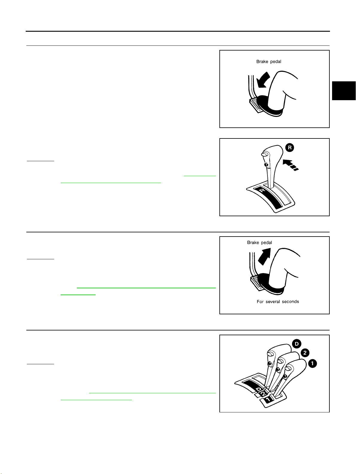
TROUBLE DIAGNOSIS — BASIC INSPECTION
[EURO-OBD]
5. CHECK SHIFT SHOCK
1. Apply foot brake.
2. Move selector lever to “R” position.
3. Is there large shock when changing from “N” to “R” position?
Yes or No
Yes >> Mark the bo x on the D I A G NO ST I C WOR K S H E ET. Go
To " 5. L arg e S ho c k “ N” → “R” Position”, AT-236, "
Large Shock. “N” → “R” Position" .ContinueROAD
TEST .
No >> GO TO 6
5.
SAT797A
SAT772B
A
B
AT
D
E
F
G
H
6. CHECK VEHICLE MOVE
1. Release foot brake for several seconds.
2. Does vehicle creep backward when foot brake is released?
Yes or No
Yes >> GO TO 7
No >> Mark the box on the DIAGNOSTIC WORKSHEET. Go
To " 6. Ve h icl e D oe s N ot C re e p B ac k wa r d I n “ R” P os i tion”, AT-237, "
“R” Position" .ContinueROADTEST.
6. Vehicle Does N ot Creep Backward In
7. CHECK VEHICLE MOVE
1. Move selector lever to “D”, “2” and “1” positions and check if
vehicle creeps forward.
2. Does vehicle creep forward in all three positions?
Yes or No
Yes >> Go To "3. C RU I S E TEST", $ $$ $ $ .
No >> Mark the box on the DIAGNOSTIC WORKSHEET. Go
To " 7 . Ve hic le Do es N ot C r ee p F orw ard I n “ D” , “ 2” Or “ 1”
Position”, AT-240, "
In “D”, “2” Or “1” Position" .ContinueROADTEST.
7. Vehicle Does Not Creep Forward
I
J
K
L
SAT799A
M
AT-73
SAT773B
Page 78
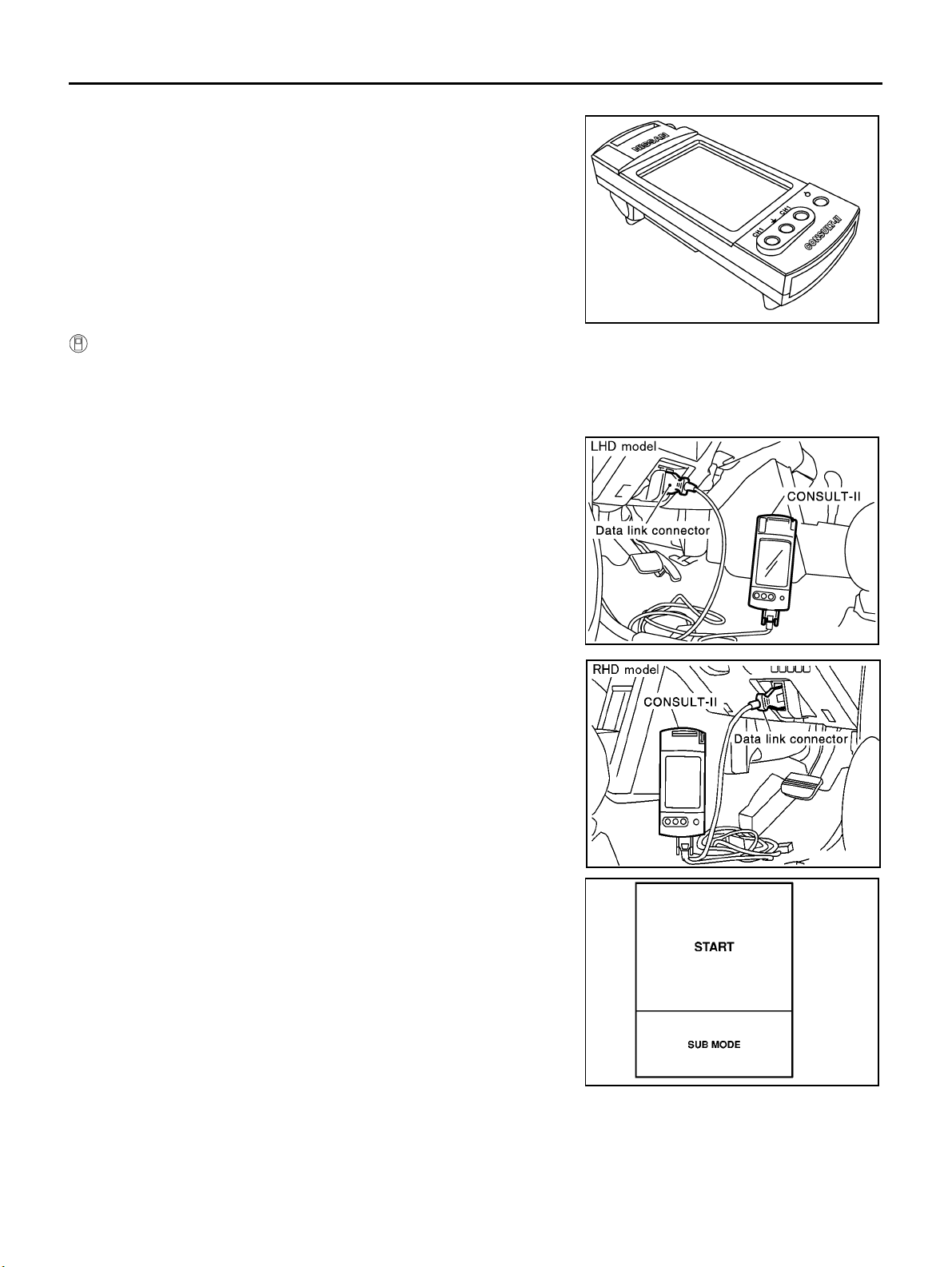
TROUBLE DIAGNOSIS — BASIC INSPECTION
3. CRUISE TEST
● Check all items listed in Parts 1 through 3.
With CONSULT-II
● Using CONSULT-II, conduct a cruise test and record the result.
● Print the result and ensure that shi fts and lock-ups take place as per Shift Schedule.
CONSULT-II Setting Procedure
1. Turn ignition switch “OFF”.
2. Connect CONSULT-II to data link connector, which is located in
left side lower dash panel.
[EURO-OBD]
SAT601J
3. Turn ignition switch “ON”.
4. Touch “START”.
SCIA0691E
SCIA0692E
SAT586J
AT-74
Page 79
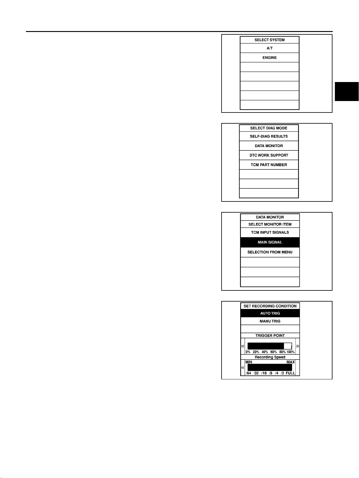
TROUBLE DIAGNOSIS — BASIC INSPECTION
5. Touch “A/T”.
6. Touch “DATA MONITOR”.
[EURO-OBD]
A
B
AT
SAT014K
D
E
F
G
SAT971J
7. Touch “MAIN SIGNALS” or “TCM INPUT SIGNALS”.
8. Select “Numerical Display”, “Barchart Display” or “Line Graph
Display”.
9. Touch “SETTING” to recording condition (“AUTO TRIG” or
“MANU TRIG”) and touch “BACK”.
10. Touch “Start”.
SAT175K
SAT973J
H
I
J
K
L
M
AT-75
Page 80
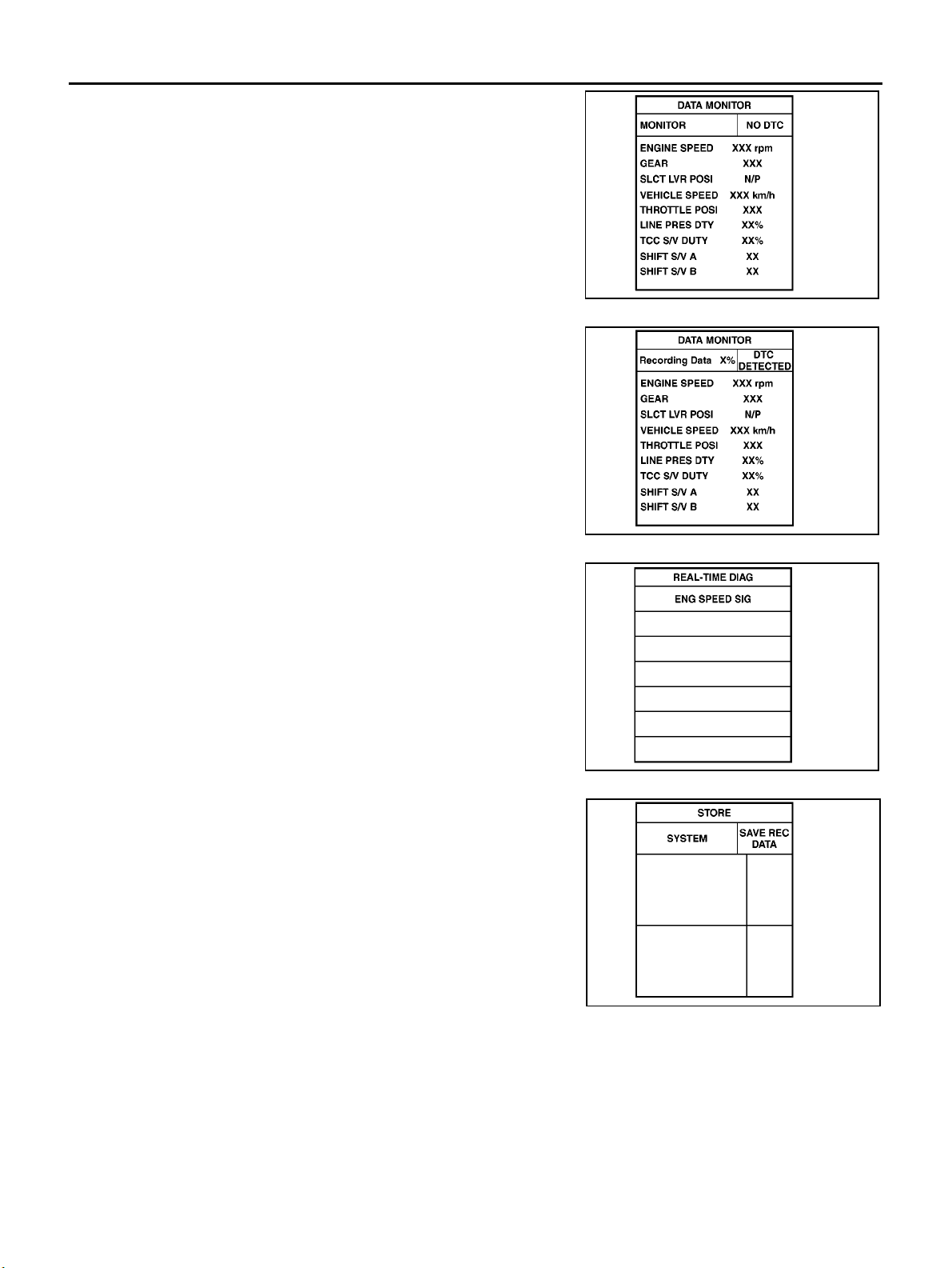
TROUBLE DIAGNOSIS — BASIC INSPECTION
11. When performing cruise tes t, t o uch “RECORD”.
12. After finishing cruise test part 1, touch “STOP”.
[EURO-OBD]
SAT134K
13. Touch “STORE” and touch “BACK”.
SAT135K
SAT987J
AT-76
SAT974J
Page 81
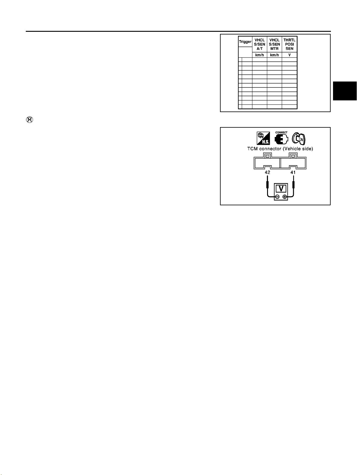
TROUBLE DIAGNOSIS — BASIC INSPECTION
14. Touch “DISPLAY”.
15. Touch “PRINT”.
16. Check the monitor data printed out.
17. Continue cruise test part 2 and 3.
Without CONSULT-II
● Throttle position sensor can be checked by voltage across termi-
nals 41 and 42 of TCM.
[EURO-OBD]
A
B
AT
SAT975J
D
E
F
G
SCIA0710E
H
I
J
K
L
M
AT-77
Page 82
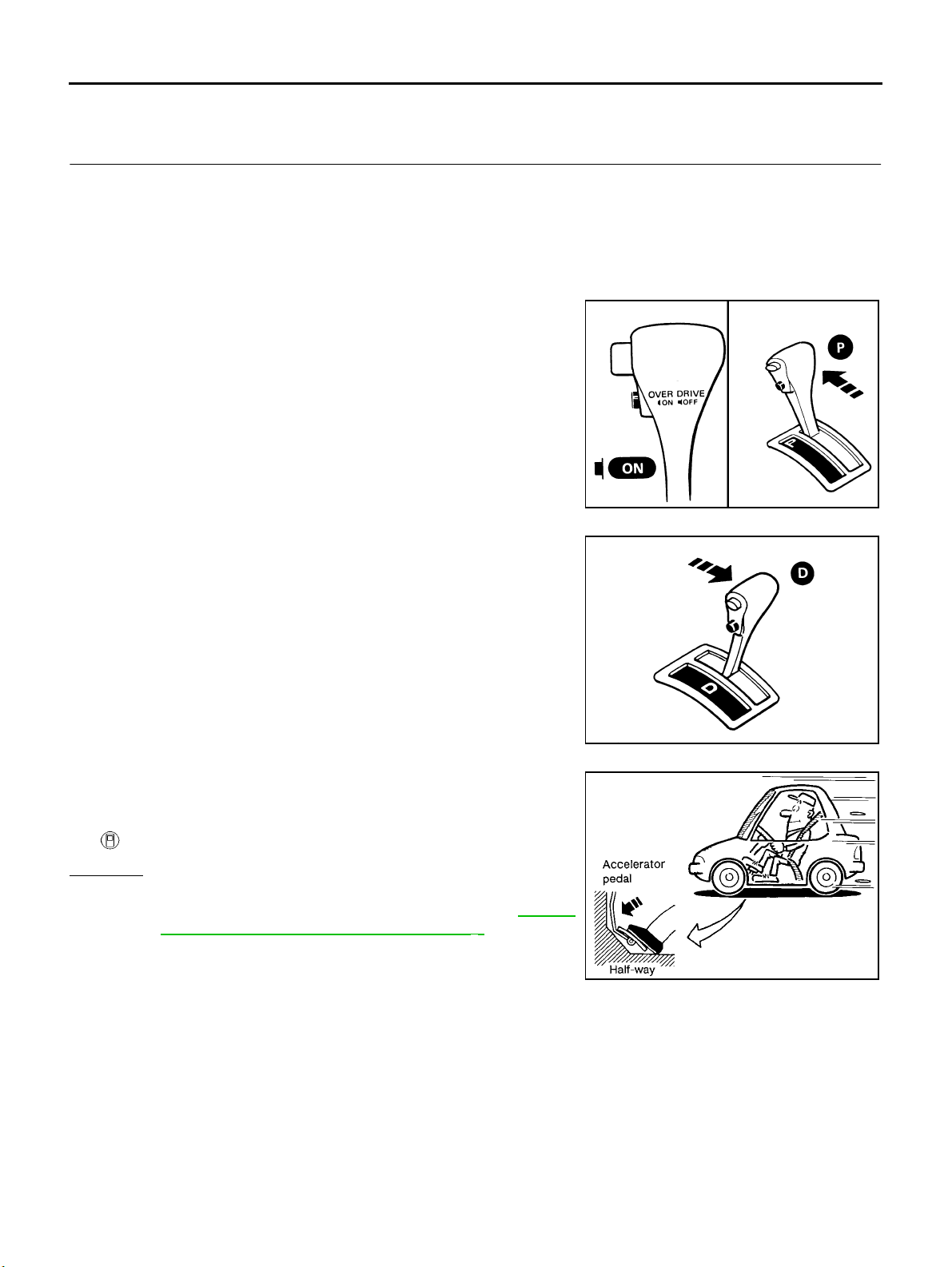
TROUBLE DIAGNOSIS — BASIC INSPECTION
Cruise Test — Part 1
1. CHECK STARTING GEAR (D1 )POSITION
1. Drive vehicle for approx. 10 minutes to warm engine oi l and ATF up to operating
temperature.
ATF operatin g temper ature : 50 - 80°C(122-176°F)
2. Park vehicle on flat surface.
3. Set overdrive control switch to “ON” position.
4. Move selector lever to “P ” position.
5. Start engine.
[EURO-OBD]
SAT774B
6. Move selector lever to “D” position.
7. Accelerate vehicle by constantly depressing accelerator pedal
halfway.
8. Does vehicle start from D
Read gear position.
Yes o r No
Yes >> G O TO 2
No >> Go To "8. Vehicle Cannot Be Started From D
"8. Vehicle Cannot Be Started From D1" .Continue
ROAD TEST.
1 ?
1 ”, AT-242,
SAT775B
SAT495G
AT-78
Page 83
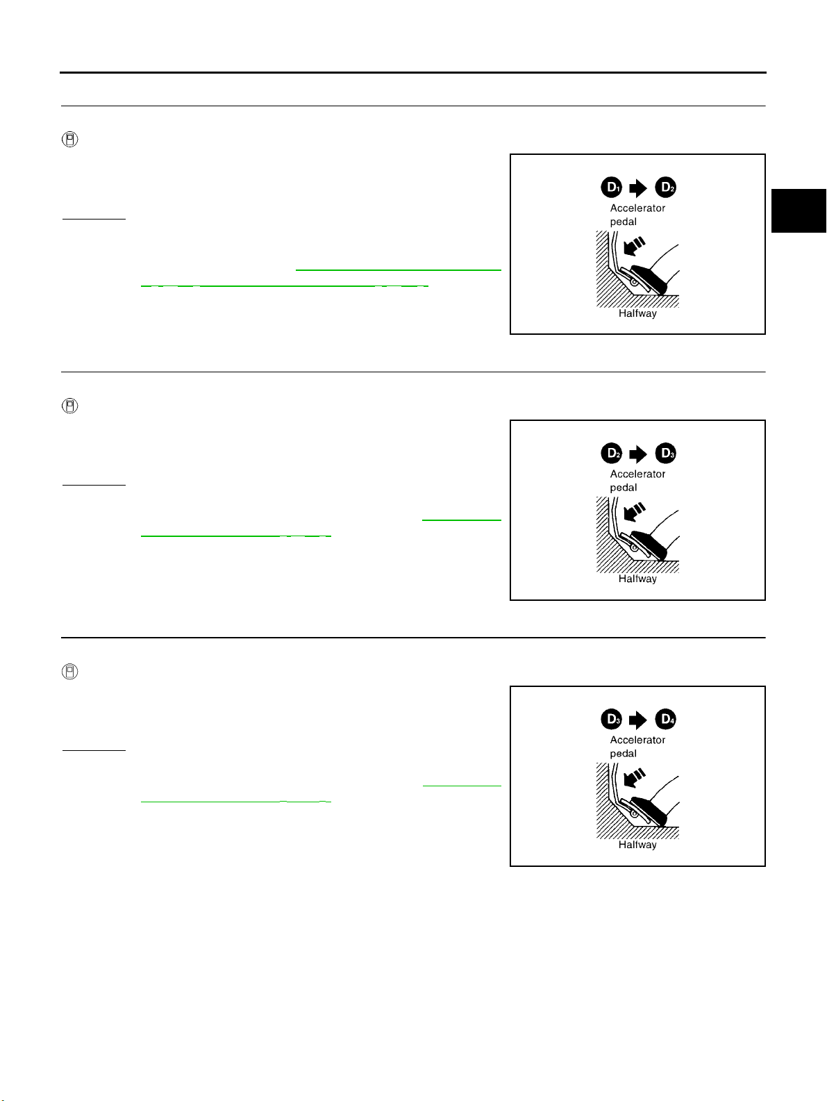
TROUBLE DIAGNOSIS — BASIC INSPECTION
[EURO-OBD]
2. CHECK SHIFT UP (D1 TO D2 )
Does A/T shift from D
Read gear position, throttle opening and vehicle speed.
Specified speed when shifting from D
Yes or No
Yes >> GO TO 3
No >> Go To "9. A/T Does Not Shift: D
Kickdown: D
D1 → D2 Or Does Not Kickdown: D4 → D2" .Continue
ROAD TEST.
1 to D2 at the specified speed?
1 to D 2 :
Refer to Shift schedule, $$$$$.
1 → D2 Or Does Not
4 → D2 ”, AT-244, "9. A/T Does Not Shift:
3. CHECK SHIFT UP (D2 TO D3 )
Does A/T shift from D
Read gear position, throttle position and vehicle speed.
Specified speed when shifting from D2 to D3 :
Yes or No
Yes >> GO TO 4
No >> Go To "10. A/T Does Not Shift: D
A/T Does Not Shift: D2 → D3" .ContinueROADTEST.
2 to D3 at the specified speed?
Refer to Shift schedule, $$$$$.
2 → D3 ”, AT-246, "10.
SAT954I
A
B
AT
D
E
F
G
H
I
4. CHECK SHIFT UP (D3 TO D4 )
Does A/T shift from D
Read gear position, throttle position and vehicle speed.
Specified speed when shifting from D3 to D4 :
Yes or No
Yes >> GO TO 5
No >> Go To "11. A/T Does Not Shift: D
A/T Does Not Shift: D3 → D4" .ContinueROADTEST.
3 to D4 at the specified speed?
Refer to Shift schedule, $$$$$.
3 → D4 ”, AT-249, "11.
SAT955I
SAT956I
J
K
L
M
AT-79
Page 84
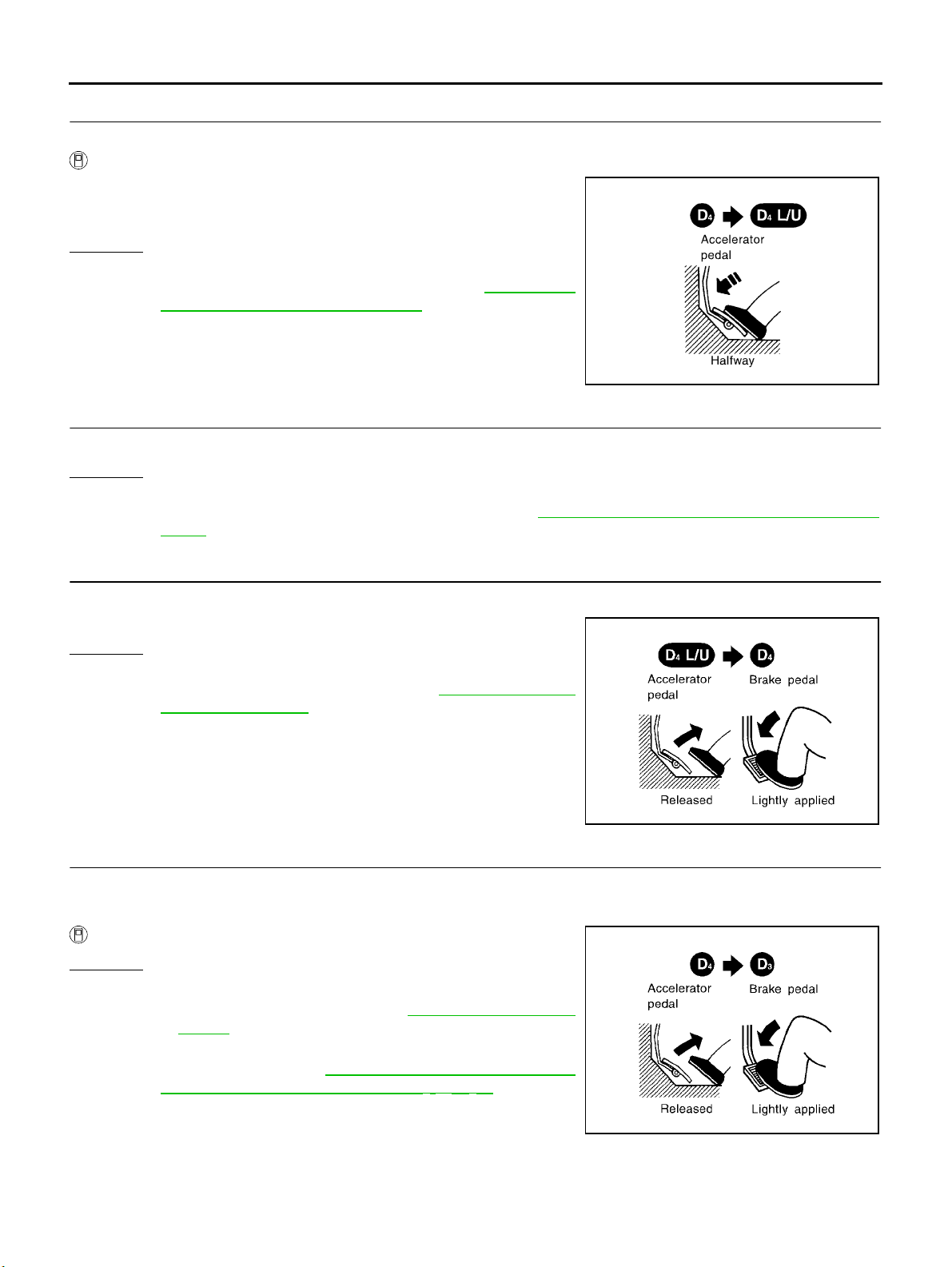
TROUBLE DIAGNOSIS — BASIC INSPECTION
5. CHECK LOCK-UP (D4 TO D4 L/U)
Does A/T perform lock-up at the specified speed?
Read vehicle speed, throttle position when lock-up duty becomes 94%.
Specified speed when lock-up occurs:
Refer to Shift schedule, $$$$$.
Yes o r No
Yes >> G O TO 6
No >> Go To "12. A/T Does Not Perfo rm Lock-up”, AT-2 5 2 , "
A/T Does Not Perform Lo ck-up" .ContinueROAD
TEST.
12.
6. CHECK HOLD LOCK-UP
Does A/T hold lock-up condition for more than 30 seconds?
Yes o r No
Yes >> G O TO 7
No >> Go To "13. A/T Does Not Hold Lock-up Condition”, AT-25 3 , "
dition" .
[EURO-OBD]
SAT957I
13. A/T Does Not Hol d Lock-up Con-
7. CHECK SHIFT DOWN (D4 L/U TO D4 )
1. Release accelerator pedal.
2. Is lock-up released when accelerator pedal is relea sed?
Yes o r No
Yes >> G O TO 8
No >> Go To "14. Lock-up Is Not Released”, AT-254, "
up Is Not Released" .ContinueROADTEST.
14. Lock-
8. CHECK SHIFT DOWN (D4 TO D3 )
1. Decelerate vehicle by applying foot brake lightly.
2. Does engine speed return to idle smoothly when A/T is shifted from D
Read gear position and engine speed.
Yes o r No
Yes >> 1 . Stop v e h ic l e .
2. Go To “Cruise test — Part 2”, AT-81 , "Cruise Test —
Part 2" .
No >> Go To "15. Engine Speed Does Not Return To Idle (Light
Braking D
Not Return To Idle (Light Braking D4 → D3 )" .Continue
ROAD TEST.
4 → D3 )”, AT-255, "15. Engine Speed Does
SAT958I
4 to D3 ?
SAT959I
AT-80
Page 85
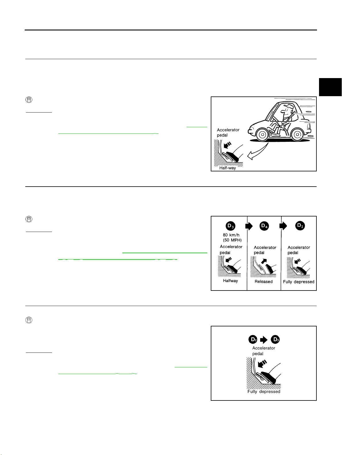
TROUBLE DIAGNOSIS — BASIC INSPECTION
Cruise Test — Part 2
1. CHECK STARTING GEAR (D1 )POSITION
[EURO-OBD]
A
1. Confirm overdrive control switch is in “ON” position.
2. Confirm selector lever is in “D” position.
3. Accelerate vehicle by half throttle again.
4. Does vehicle start from D
Read gear position.
Yes or No
Yes >> GO TO 2
No >> Go To "16. Vehicle Does Not Start From D
"16. Vehicle Does Not Start From D1" .ContinueROAD
TEST .
1 ?
1 ”, AT-257,
2. CHECK SHIFT UP AND SHIFT DOWN (D3 TO D4 TO D2 )
1. Accelerate vehicle to 80 km/h (50 MPH) as shown in illustration.
2. Release accelerator pedal and then quickly depress it fully.
3. Does A/T shift from D
Read gear position and throttle position.
Yes or No
Yes >> GO TO 3
No >> Go To "9. A/T Does Not Shift: D
Kickdown: D
D1 → D2 Or Does Not Kickdown: D4 → D2" .Continue
ROAD TEST.
4 to D2 as soon as accelerator pedal is depressed fully?
1 → D2 Or Does Not
4 → D2 ”, AT-244, "9. A/T Does Not Shift:
B
AT
D
E
F
SAT495G
G
H
I
J
K
3. CHECK SHIFT UP (D2 TO D3 )
Does A/T shift from D
Read gear position, throttle position and vehicle speed.
Specified speed when shifting from D2 to D3 :
Yes or No
Yes >> GO TO 4
No >> Go To "10. A/T Does Not Shift: D
A/T Does Not Shift: D2 → D3" .ContinueROADTEST.
2 to D3 at the specified speed?
Refer to Shift Schedule, $$$$$.
2 → D3 ”, AT-246, "10.
AT-81
SAT404H
L
M
SAT960I
Page 86
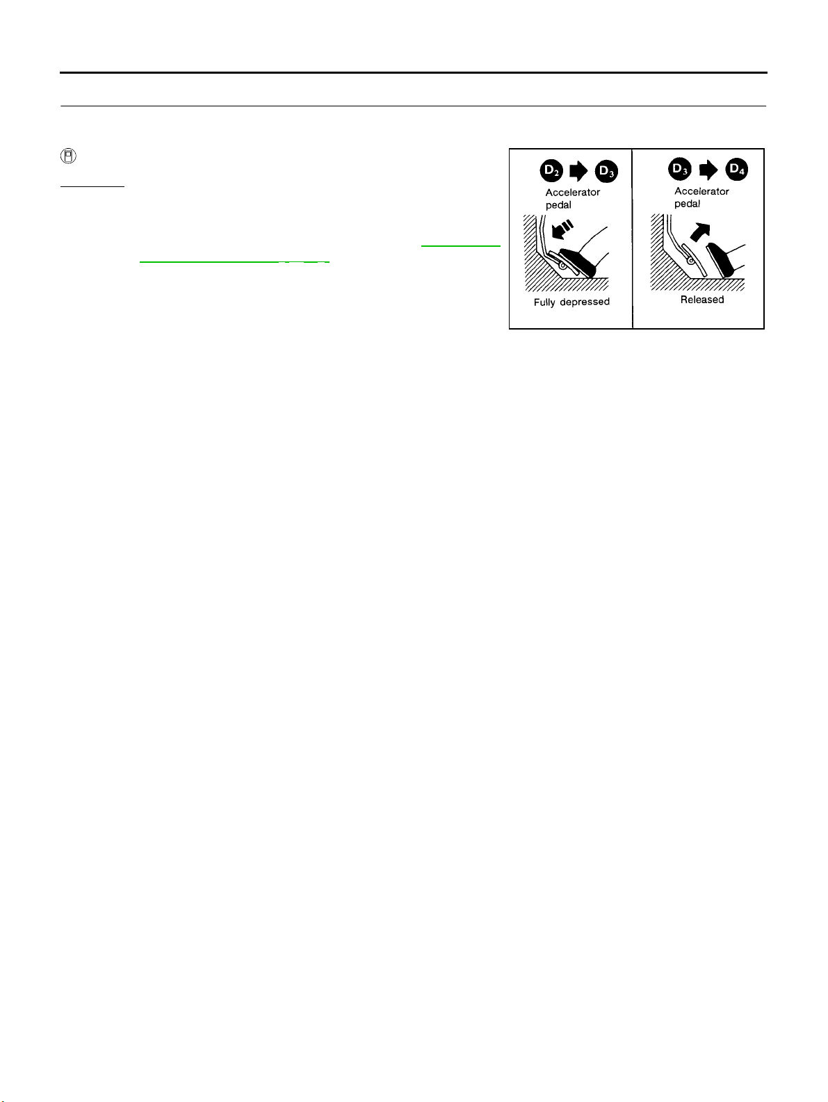
TROUBLE DIAGNOSIS — BASIC INSPECTION
4. CHECK SHIFT UP (D3 TO D4 )ANDENGINEBRAKE
[EURO-OBD]
Release accelerator pedal after shifting from D
Does A/T shift from D
Read gear position, throttle position and vehicle speed.
Yes o r No
Yes >> 1 . Stop v e h ic l e .
2. Go To “Cruise test — Part 3”, $$$$$.
No >> Go To "11. A/T Does Not Shift: D
A/T Does Not Shift: D3 → D4" .ContinueROADTEST.
3 to D4 and does vehicle decelerate by engine brake?
2 to D3 .
3 → D4 ”, AT-249, "11.
SAT405H
AT-82
Page 87
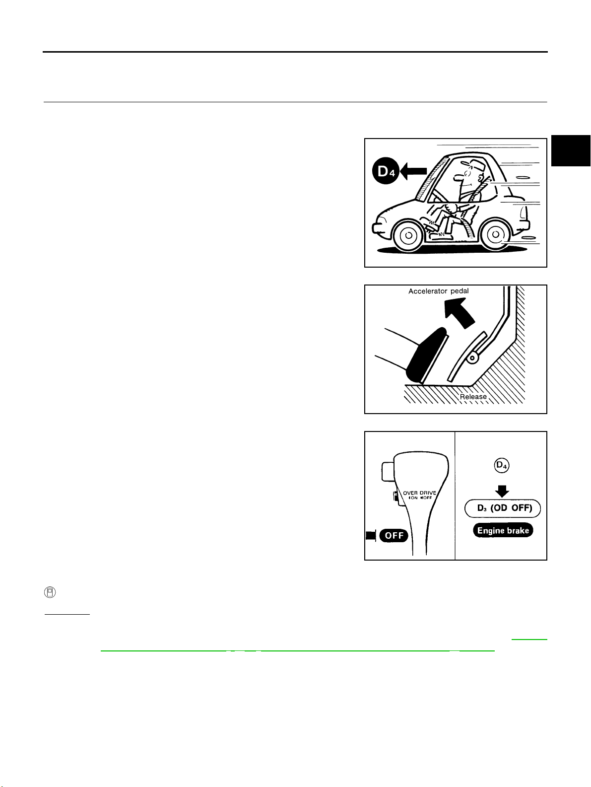
TROUBLE DIAGNOSIS — BASIC INSPECTION
Cruise Test — Part 3
1. CHECK SHIFT DOWN (D4 TO D3 )
[EURO-OBD]
A
1. Confirm overdrive control switch is in “ON” position.
2. Confirm selector lever is in “D” position.
3. Accelerate vehicle using half-throttle to D
4 .
4. Release accelerator pedal.
B
AT
D
E
SAT812A
F
G
H
I
5. Set overdrive control switch to “OFF” position while driving in D4
.
6. Does A/T shift from D
4 to D3 (O/D OFF)?
Read gear position and vehicle speed.
Yes or No
Yes >> GO TO 2
No >> Go To "17. A/T Does Not Shift: D
4 → D3 ,WhenOverdriveControlSwitch“ON”→ “OFF”, AT-258,
"17. A/T Does Not Sh ift: D4 → D3 ,WhenOverdriveControlSwitch“ON” → “OFF”" .Continue
ROAD TEST.
SAT813A
SAT776BA
J
K
L
M
AT-83
Page 88
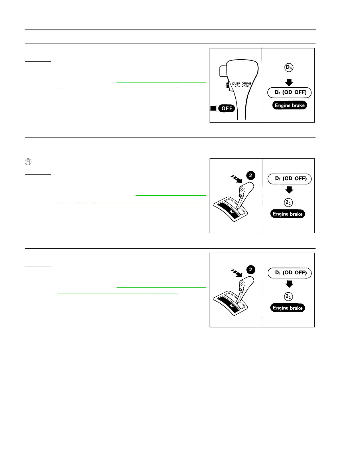
TROUBLE DIAGNOSIS — BASIC INSPECTION
2. CHECK ENGINE BRAKE
Does vehicle decelerate by engine brake?
Yes o r No
Yes >> G O TO 3
No >> Go To "15. Engine Speed Does Not Return To Idle (Light
Braking D
Not Return To Idle (Light Braking D4 → D3 )" .Continue
ROAD TEST.
4 → D3 )”, AT-255, "15. Engine Speed Does
3. CHECK SHIFT DOWN (D3 TO D2 )
[EURO-OBD]
SAT776BA
1. Move selector lever from “D” to “2” position while driving in D
2. Does A/T shift from D
Read gear position.
Yes o r No
Yes >> G O TO 4
No >> Go To "18. A/T Does Not Shift: D
tor Lever “D” → “2” Position”, AT- 2 5 8, "
Shift: D3 → 22 ,WhenSelectorLever“D” → “2” Position"
.ContinueROADTEST.
3 (O/D OFF) to 22 ?
3 → D2 ,WhenSelec-
18. A/T Does Not
4. CHECK ENGINE BRAKE
Does vehicle decelerate by engine brake?
Yes o r No
Yes >> G O TO 5
No >> Go To "15. Engine Speed Does Not Return To Idle (Light
Braking D
Not Return To Idle (Light Braking D4 → D3 )" .Continue
ROAD TEST.
4 → D3 )”, AT-255, "15. Engine Speed Does
3 (O/D OFF).
SAT791GA
AT-84
SAT791GA
Page 89
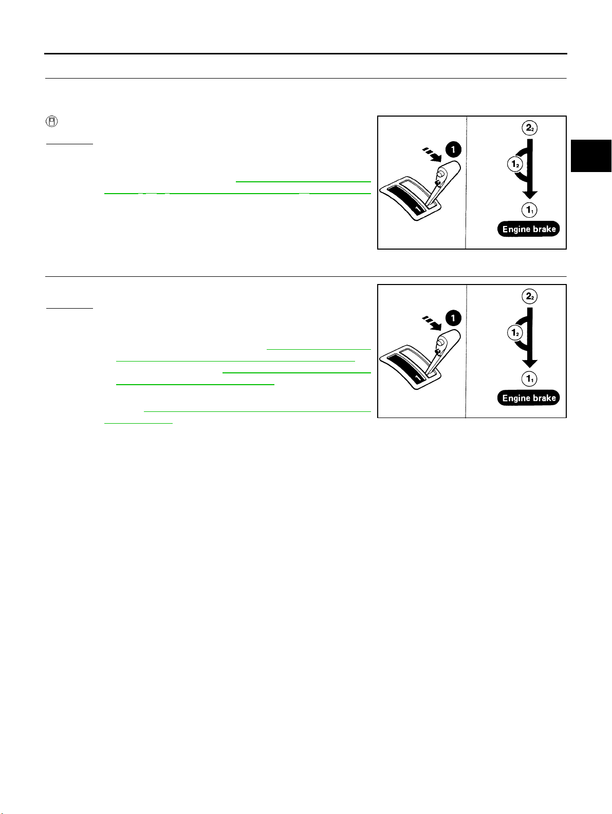
TROUBLE DIAGNOSIS — BASIC INSPECTION
[EURO-OBD]
5. CHECK SHIFT DOWN
1. Move selector lever from “2” to “1” position while driving in 2
2. Does A/T shift from 22 to 11 position?
Read gear position.
Yes or No
Yes >> GO TO 6
No >> Go To "19. A/T Does Not Shift: 2
lever “2” → “1” Position”, AT-259 , "
Shift: 22 → 11 ,WhenSelectorLever“2” → “1” Position"
.ContinueROADTEST.
2 → 11 ,WhenSelector
19. A/T Does Not
6. CHECK ENGINE BRAKE
Does vehicle decelerate by engine brake?
Yes or No
Yes >> 1. Stop ve hi c l e .
2. Perform self-diagnosis.
Except for Euro-OBD: Refer to AT-273 , "
NOSTIC PROCEDURE (WITHOUT CONSULT-II)" ,
EURO-OBD: Refer to AT-5 1, "
TIC PROCEDURE (NO TOOLS)" .
No >> Go To "20. Vehicle Does Not Decelerate By Engine
Brake”, AT-2 59, "
Engine Brake" .ContinueROADTEST.
20. Vehicle Does Not Decelerate By
TCM SELF-DIAGNOS-
SELF-DIAG-
2 .
SAT778B
SAT778B
A
B
AT
D
E
F
G
H
I
K
M
J
L
AT-85
Page 90

TROUBLE DIAGNOSIS — GENERAL DESCRIPTION
[EURO-OBD]
TROUBLE DIAGNOSIS — GENERAL DESCRIPTION
Symptom Chart
Numbers are arranged in order of inspection.
Perform inspections starting with number one and w ork up.
Symptom Condition Diagnostic Item
1. Ignition switch and starter
Engine cannot start in “P” and “N”
positions.
AT-2 3 3, "
Started In “P” and “N” Position"
Engine starts in position other than
“N” and “P” positions.
AT-2 3 3, "
Started In “P” and “N” Position"
2. Engine Cannot Be
2. Engine Cannot Be
ON vehicle
ON vehicle
2. Control cable adjustment
3. PNP switch adjustment
1. Control cable adjustment
2. PNP switch adjustment
PFP:00000
Reference Page
Except for
Euro-OBD
PG-2, "
ROUTING", SC-21,
"STARTING SYSTEM"
AT-4 56,
"Control
Cable
Adjustment"
AT-4 56,
"Park/Neutral Position
(PNP)
Switch
Adjustment"
AT-4 56,
"Control
Cable
Adjustment"
AT-4 56,
"Park/Neutral Position
(PNP)
Switch
Adjustment"
EURO-OBD
POWER SUPPLY
←
←
←
←
ECS004QU
AT-86
Page 91

TROUBLE DIAGNOSIS — GENERAL DESCRIPTION
[EURO-OBD]
Symptom Condition Diagnostic Item
Transaxle noise in “P” and “N” positions.
Vehicle moves when changing into
“P” position, or parking gear does
not disengage when shifted out of
“P” position.
AT-23 4, "
Moves Forward Or Backward When
Pushed"
3. In “P” Position, Vehicle
1. Fluid level
2. Line pressure test
3. Throttle position sensor (Accelerator
pedal position (App) sensor) Ajustment
ON vehicle
4. Vehicle speed sensor·A/T (Revolution
sensor) and vehicle speed sensor·MTR
5. Engine speed signal
6. Oil pump
OFF vehicle
7. Torque converter
ON vehicle 1. Control cable adjustment
OFF vehicle 2. Parking components
Reference Page
Except for
Euro-OBD
AT-6 4 ,
"FLUID
LEVEL
CHECK"
Line
AT-6 8 , "
Pressure
Test"
EC-154, "
SENSOR"
AT-3 9 2,
"VEHICLE
SPEED
SENSOR·A/
T(REVOLUTION
SENSOR)",
AT-3 9 7,
"DTC VEHICLE
SPEED
SENSOR
MTR"
AT-4 3 2,
"ENGINE
SPEED
SIGNAL"
AT-4 8 5, "
Pump"
AT-4 6 5,
"Locations
of Adjusting
Shims, Needle Bearings, Thrust
Washers
and Snap
Rings"
AT-4 5 6,
"Control
Cable
Adjustment"
AT-4 6 1,
"Components", AT482,
"REPAIR
FOR COMPONENT
PARTS"
DTC P0121 APP
Oil
EURO-OBD
←
←
AT-1 4 2,
"DTC P0720
VEHICLE
SPEED
SENSOR·A/
T(REVOLUTION
SENSOR)",
AT-2 2 2,
"DTC VEHICLE SPEED
SENSOR
MTR"
AT-1 4 7,
"DTC P0725
ENGINE
SPEED
SIGNAL"
←
←
←
←
A
B
AT
D
E
F
G
H
I
J
K
L
M
AT-87
Page 92
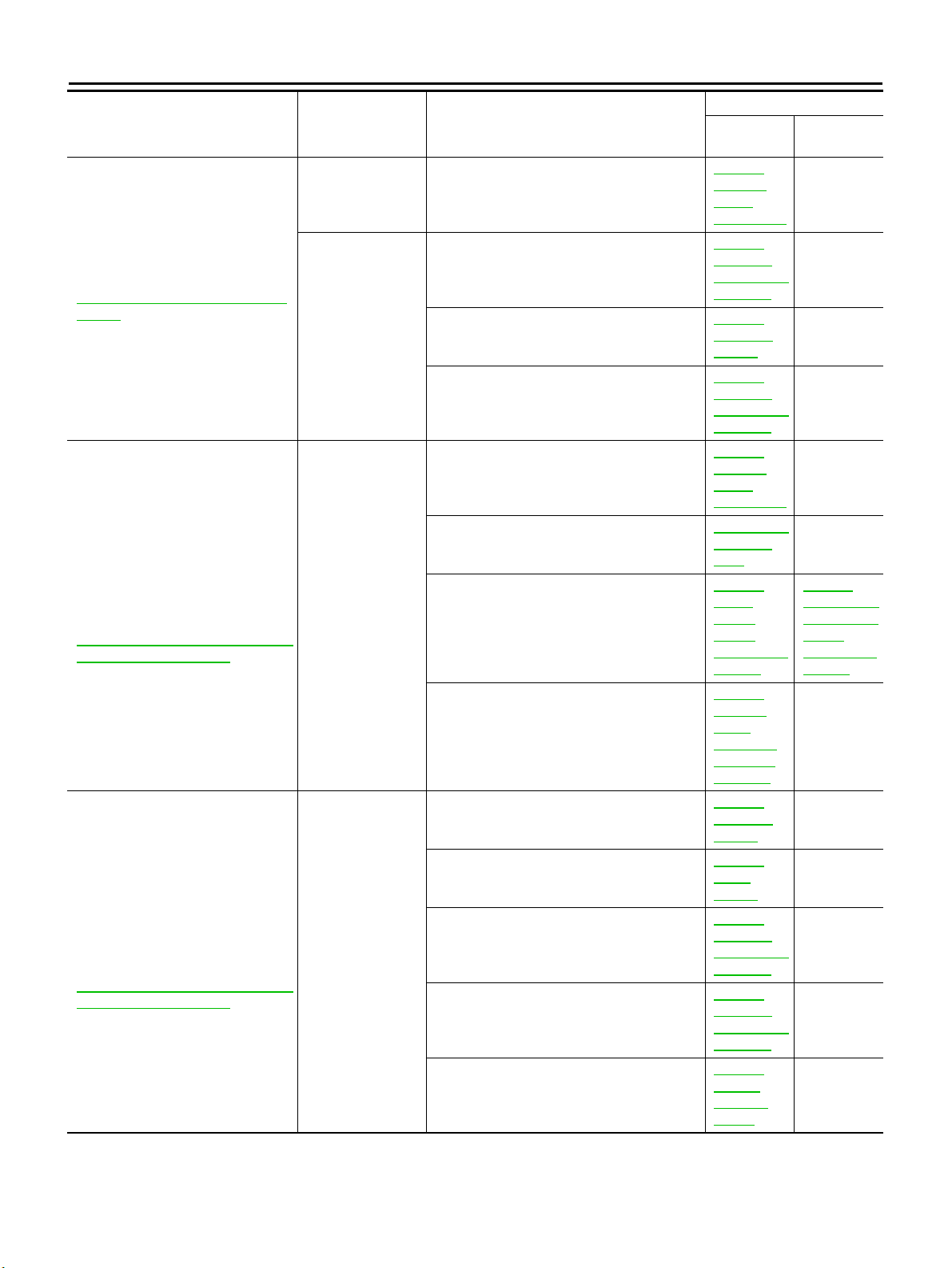
TROUBLE DIAGNOSIS — GENERAL DESCRIPTION
Symptom Condition Diagnostic Item
Vehicle runs in “N” position.
AT-2 3 4, "
Moves"
Vehicle will not run in “R” position
(but runs in “D”, “2” and “1” positions). Clutch slips.
Very poor a cceleration.
AT-2 3 7, "
Backward In “R” Position"
Vehicle will not run in “R” position
(but runs in “D”, “2” and “1” positions). Clutch slips.
Very poor a cceleration.
AT-2 3 7, "
Backward In “R” Position"
4. In “N” Position, Vehicle
6. Vehicle Does Not Creep
6. Vehicle Does Not Creep
ON vehicle 1. Control cable adjustment
2. Forward clutch
OFF vehicle
ON vehicle
OFF vehicle
3. Reverse clutch
4. Overrun clutch
1. Control cable adjustment
2. Line pressure test
3. Line pressure solenoid valve
4. Control valve assembly
5. Reverse clutch
6. High clutch
7. Forward clutch
8. Overrun clutch
9. Low & reverse brake
[EURO-OBD]
Reference Page
Except for
Euro-OBD
AT-4 56,
"Control
Cable
Adjustment"
AT-5 12,
"Forward
and Overrun
Clutches"
AT-5 04,
"Reverse
Clutch"
AT-5 12,
"Forward
and Overrun
Clutches"
AT-4 56,
"Control
Cable
Adjustment"
Line
AT-6 8, "
Pressure
Te s t "
AT-4 36,
"LINE
PRESSURE
SOLENOID
VALV E "
AT-4 54,
"Control
Val ve
Assembly
and Accumulators"
AT-5 04,
"Reverse
Clutch"
AT-5 07,
"High
Clutch"
AT-5 12,
"Forward
and Overrun
Clutches"
AT-5 12,
"Forward
and Overrun
Clutches"
AT-5 18,
"Low &
Reverse
Brake"
EURO-OBD
←
←
←
←
←
←
AT-1 86,
"DTC P0745
LINE PRESSURE
SOLENOID
VALV E"
←
←
←
←
←
←
AT-88
Page 93

TROUBLE DIAGNOSIS — GENERAL DESCRIPTION
[EURO-OBD]
Symptom Condition Diagnostic Item
Vehicle braked when sh iftin g into
“R” position.
ON vehicle
OFF vehicle
1. Fluid level
2. Control cable adjustment
3. Line pressure test
4. Line pressure solenoid valve
5. Control valve assembly
6. High clutch
7. Brake band
8. Forward clutch
9. Overrun clutch
Reference Page
Except for
Euro-OBD
AT-6 4 , "
A/T
Fluid
Check"
AT-4 5 6,
"Control
Cable
Adjustment"
Line
AT-6 8 , "
Pressure
Test"
AT-4 3 6,
"LINE
PRESSURE
SOLENOID
VALV E"
AT-4 5 4,
"Control
Valve
Assembly
and Accumulators"
AT-5 0 7,
"High
Clutch"
AT-5 3 0,
"Band
Servo Piston Assembly"
AT-5 1 2,
"Forward
and O verrun
Clutches"
AT-5 1 2,
"Forward
and O verrun
Clutches"
EURO-OBD
←
←
←
AT-1 8 6,
"DTC P0745
LINE PRESSURE
SOLENOID
VALV E"
←
←
←
←
←
A
B
AT
D
E
F
G
H
I
J
K
L
AT-89
M
Page 94
TROUBLE DIAGNOSIS — GENERAL DESCRIPTION
Symptom Condition Diagnostic Item
Sharp shock in shifting from “N” to
“D” position.
1. Engine idling rpm
2. Throttle position sensor Accelerator pedal
position (App) sensor Adjustment
3. Line pressure test
4. A/T fluid temp sen circ and TCM pow sour
ON vehicle
5. Engine speed signal
6. Line pressure solenoid valve
7. Control valve assembly
8. Accumulator N-D
OFF vehicle 9. Forward clutch
[EURO-OBD]
Reference Page
Except for
Euro-OBD
EC-XX, “Idle
Speed and
Ignition Timing”
EC-154, "
SENSOR"
AT-6 8, "
Pressure
Te s t "
AT-4 26,
"BATT/
FLUID
TEMP SEN
(A/T FLUID
TEMP SENSOR CIRCUIT AND
TCM
POWER
SOURCE)"
AT-4 32,
"ENGINE
SPEED
SIGNAL"
AT-4 36,
"LINE
PRESSURE
SOLENOID
VALV E "
AT-4 54,
"Control
Val ve
Assembly
and Accumulators"
AT-4 54,
"Control
Val ve
Assembly
and Accumulators"
AT-5 12,
"Forward
and Overrun
Clutches"
DTC P0121 APP
Line
EURO-OBD
←
←
AT-2 16,
"DTC BATT/
FLUID
TEMP SEN
(A/T FLUID
TEMP SENSOR CIRCUIT AND
TCM
POWER
SOURCE)"
AT-1 47,
"DTC P0725
ENGINE
SPEED
SIGNAL"
AT-1 86,
"DTC P0745
LINE PRESSURE
SOLENOID
VALV E"
←
←
←
AT-90
Page 95

TROUBLE DIAGNOSIS — GENERAL DESCRIPTION
[EURO-OBD]
Symptom Condition Diagnostic Item
Vehicle will not run in “D” and “2”
positions (but runs in “1” and “R”
positions).
Vehicle wi ll not run in “D”, “1”, “2”
positions (but runs in “R” position).
Clutch slips. Very poor acceleration.
AT-24 0, "
Forward In “D”, “2” Or “1” Position"
7. Vehicle Does Not C reep
ON vehicle 1. Control cable adjustment
OFF vehicle 2. Low one-way clutch
1. Fluid level
2. Line pressure test
3. Line pressure solenoid valve
ON vehicle
4. Control valve assembly
5. Accumulator N-D
Reference Page
Except for
Euro-OBD
AT-4 5 6,
"Control
Cable
Adjustment"
AT-4 6 1,
"OVERHAUL", AT465, "Locations of
Adjusting
Shims, Needle Bearings, Thrust
Washers
and Snap
Rings"
AT-6 4 ,
"FLUID
LEVEL
CHECK"
Line
AT-6 8 , "
Pressure
Test"
AT-4 3 6,
"LINE
PRESSURE
SOLENOID
VALV E"
AT-4 5 4,
"Control
Valve
Assembly
and Accumulators"
AT-4 5 4,
"Control
Valve
Assembly
and Accumulators"
EURO-OBD
←
←
←
←
AT-1 8 6,
"DTC P0745
LINE PRESSURE
SOLENOID
VALV E"
←
←
A
B
AT
D
E
F
G
H
I
J
K
L
M
AT-91
Page 96
TROUBLE DIAGNOSIS — GENERAL DESCRIPTION
Symptom Condition Diagnostic Item
Vehicle will not run in “ D”, “1 ”, “2”
positions (but runs in “R” position).
Clutch slips. Very poor acceleration.
AT-2 4 0, "
Forward In “D”, “2” Or “1” Position"
7. Vehicle Does Not Creep
OFF vehicle
6. Reverse clutch
7. High clutch
8. Forward clutch
9. Forward one-way clutch
10. Low one-way clutch
[EURO-OBD]
Reference Page
Except for
Euro-OBD
AT-5 04,
"Reverse
Clutch"
AT-5 07,
"High
Clutch"
AT-5 12,
"Forward
and Overrun
Clutches"
AT-4 61,
"OVERHAUL"
AT-4 61,
"OVERHAUL", AT465, " Locations of
Adjusting
Shims, Needle Bearings, Thrust
Washers
and Snap
Rings"
EURO-OBD
←
←
←
←
←
AT-92
Page 97
TROUBLE DIAGNOSIS — GENERAL DESCRIPTION
[EURO-OBD]
Symptom Condition Diagnostic Item
Clutches or brakes slip somewhat in
starting.
ON vehicle
OFF vehicle
1. Fluid level
2. Control cable adjustment
3. Throttle position sensor (Accelerator
pedal position (App) sensor) Adjustment
4. Line pressure test
5. Line pressure solenoid valve
6. Control valve assembly
7. Accumulator N-D
8. Forward clutch
9. Reverse clutch
10. Low & reverse brake
11. O il p u mp
12. Torque converter
Reference Page
Except for
Euro-OBD
AT-6 4 ,
"FLUID
LEVEL
CHECK"
AT-4 5 6,
"Control
Cable
Adjustment"
EC-154, "
SENSOR"
AT-6 8 , "
Pressure
Test"
AT-4 3 6,
"LINE
PRESSURE
SOLENOID
VALV E"
AT-4 5 4,
"Control
Valve
Assembly
and Accumulators"
AT-4 5 4,
"Control
Valve
Assembly
and Accumulators"
AT-5 1 2,
"Forward
and O verrun
Clutches"
AT-5 0 4,
"Reverse
Clutch"
AT-5 1 8,
"Low &
Reverse
Brake"
AT-4 8 5, "
Pump"
AT-4 6 5,
"Locations
of Adjusting
Shims, Needle Bearings, Thrust
Washers
and Snap
Rings"
DTC P0121 APP
Line
Oil
EURO-OBD
←
←
←
AT-1 8 6,
"DTC P0745
LINE PRESSURE
SOLENOID
VALV E"
←
←
←
←
←
←
←
A
B
AT
D
E
F
G
H
I
J
K
L
M
AT-93
Page 98

TROUBLE DIAGNOSIS — GENERAL DESCRIPTION
Symptom Condition Diagnostic Item
Excessive creep. ON vehicle 1. Engine idling rpm
1. Fluid level
2. Line pressure test
ON vehicle
No creep at all.
AT-2 3 7, "
Backward In “R” Position" and AT240, "7. Vehicle Does Not Creep
Forward In “D”, “2” Or “1” Position"
6. Vehicle Does Not Creep
OFF vehicle
3. Control valve assembly
4. Forward clutch
5. Oil pump
6. Torque converter
[EURO-OBD]
Reference Page
Except for
Euro-OBD
"EC-XX",
“Idle Speed
and Ignition
Timing ”
AT-6 4,
"FLUID
LEVEL
CHECK"
AT-4 36,
"LINE
PRESSURE
SOLENOID
VALV E "
AT-4 54,
"Control
Val ve
Assembly
and Accumulators"
AT-5 12,
"Forward
and Overrun
Clutches"
AT-4 85, "
Pump"
AT-4 65,
"Locations
of Adjusting
Shims, Needle Bearings, Thrust
Washers
and Snap
Rings"
Oil
EURO-OBD
←
←
←
←
←
←
←
AT-94
Page 99

TROUBLE DIAGNOSIS — GENERAL DESCRIPTION
[EURO-OBD]
Symptom Condition Diagnostic Item
Failure to change gear from “D1 ”to
“D
2 ”.
1. PNP switch adjustment
2. Control cable adjustment
3. Shift solenoid valve A
ON vehicle
4. Control valve assembly
5. Vehicle speed sensor·A/T (Revolution
sensor) and vehicle speed sensor·MTR
OFF vehicle 6. Brake band
Reference Page
Except for
Euro-OBD
AT-4 5 6,
"Park/Neutral Position
(PNP)
Switch
Adjustment"
AT-4 5 6,
"Control
Cable
Adjustment"
AT-4 0 6,
"SHIFT
SOLENOID
VALV E A"
AT-4 5 4,
"Control
Valve
Assembly
and Accumulators"
AT-3 9 2,
"VEHICLE
SPEED
SENSOR·A/
T(REVOLUTION
SENSOR)",
AT-3 9 7,
"DTC VEHICLE
SPEED
SENSOR
MTR"
AT-5 3 0,
"Band
Servo Piston Assembly"
EURO-OBD
←
←
AT-1 9 3,
"DTC P0750
SHIFT
SOLENOID
VALV E A"
←
AT-1 4 2,
"DTC P0720
VEHICLE
SPEED
SENSOR·A/
T(REVOLUTION
SENSOR)",
AT-2 2 2,
"DTC VEHICLE SPEED
SENSOR
MTR"
←
A
B
AT
D
E
F
G
H
I
J
K
L
AT-95
M
Page 100

TROUBLE DIAGNOSIS — GENERAL DESCRIPTION
Symptom Condition Diagnostic Item
Failure to change gear from “D2 ”to
“D
3 ”.
ON vehicle
OFF vehicle
1. PNP switch adjustment
2. Control cable adjustment
3. Shift solenoid valve B
4. Control valve assembly
5. Vehicle speed sensor·A/T (Revolution
sensor) and vehicle speed sensor·MTR
6. High clutch
7. Brake band
[EURO-OBD]
Reference Page
Except for
Euro-OBD
AT-4 56,
"Park/Neutral Position
(PNP)
Switch
Adjustment"
AT-4 56,
"Control
Cable
Adjustment"
AT-4 11,
"SHIFT
SOLENOID
VALV E B"
AT-4 54,
"Control
Val ve
Assembly
and Accumulators"
AT-3 92,
"VEHICLE
SPEED
SENSOR·A/
T(REVOLUTION
SENSOR)",
AT-3 97,
"DTC VEHICLE
SPEED
SENSOR
MTR"
AT-5 07,
"High
Clutch"
AT-5 30,
"Band
Servo Piston Assembly"
EURO-OBD
←
←
AT-1 98,
"DTC P0755
SHIFT
SOLENOID
VALV E B"
←
AT-1 42,
"DTC P0720
VEHICLE
SPEED
SENSOR·A/
T(REVOLUTION
SENSOR)",
AT-2 22,
"DTC VEHICLE SPEED
SENSOR
MTR"
←
←
AT-96
 Loading...