


 Loading...
C TRANSMISSION/TRANSAXLE
SECTION
MANUAL TRANSAXLE
CONTENTS
A
B
MT
D
E
PRECAUTIONS ......................................................... |
3 |
Caution .................................................................... |
3 |
PREPARATION .......................................................... |
4 |
Special Service Tools .............................................. |
4 |
Commercial Service Tools ....................................... |
6 |
NOISE, VIBRATION, AND HARSHNESS (NVH) |
|
TROUBLESHOOTING ............................................... |
7 |
NVH Troubleshooting Chart .................................... |
7 |
MANUAL TRANSAXLE ........................................ |
7 |
DESCRIPTION ........................................................... |
8 |
Cross-Sectional View .............................................. |
8 |
DOUBLE-CONE SYNCHRONIZER ..................... |
9 |
REVERSE GEAR NOISE PREVENTION FUNC- |
|
TION (SYNCHRONIZING METHOD) .................. |
9 |
M/T OIL .................................................................... |
10 |
Changing M/T Oil .................................................. |
10 |
DRAINING .......................................................... |
10 |
FILLING .............................................................. |
10 |
Checking M/T Oil ................................................... |
10 |
OIL LEAKAGE AND OIL LEVEL ........................ |
10 |
SIDE OIL SEAL ........................................................ |
11 |
Removal and Installation ........................................ |
11 |
REMOVAL ........................................................... |
11 |
INSTALLATION ................................................... |
11 |
POSITION SWITCH ................................................. |
12 |
Checking ............................................................... |
12 |
BACK-UP LAMP SWITCH ................................. |
12 |
PARK/NEUTRAL POSITION SWITCH .............. |
12 |
CONTROL LINKAGE .............................................. |
13 |
Removal and Installation of Control Device and |
|
Cable ..................................................................... |
13 |
AIR BREATHER HOSE ........................................... |
14 |
Removal and Installation ....................................... |
14 |
TRANSAXLE ASSEMBLY ....................................... |
15 |
Removal and Installation ....................................... |
15 |
REMOVAL .......................................................... |
15 |
INSTALLATION .................................................. |
16 |
Component Parts (RS5F51A) ............................... |
17 |
CASE AND HOUSING COMPONENTS ............. |
17 |
GEAR COMPONENTS ...................................... |
18 |
SHIFT CONTROL COMPONENTS .................... |
20 |
FINAL DRIVE COMPONENTS .......................... |
21 |
Component Parts (RS6F51A) ................................ |
22 |
CASE AND HOUSING COMPONENTS ............. |
22 |
GEAR COMPONENTS ...................................... |
23 |
SHIFT CONTROL COMPONENTS .................... |
25 |
FINAL DRIVE COMPONENTS .......................... |
26 |
Disassembly and Assembly (RS5F51A) ................ |
26 |
DISASSEMBLY .................................................. |
26 |
ASSEMBLY ........................................................ |
30 |
Disassembly and Assembly (RS6F51A) ................ |
35 |
DISASSEMBLY .................................................. |
35 |
ASSEMBLY ........................................................ |
39 |
Adjustment (RS5F51A) .......................................... |
45 |
INPUT SHAFT END PLAY ................................. |
45 |
MAINSHAFT END PLAY .................................... |
46 |
DIFFERENTIAL SIDE BEARING PRELOAD ..... |
47 |
REVERSE IDLER GEAR END PLAY ................. |
48 |
Adjustment (RS6F51A) .......................................... |
49 |
INPUT SHAFT END PLAY ................................. |
49 |
MAINSHAFT END PLAY .................................... |
50 |
DIFFERENTIAL SIDE BEARING PRELOAD ..... |
51 |
REVERSE IDLER GEAR END PLAY ................. |
52 |
INPUT SHAFT AND GEARS ................................... |
54 |
Assembly and Disassembly (RS5F51A) ................ |
54 |
DISASSEMBLY .................................................. |
54 |
INSPECTION AFTER DISASSEMBLY ............... |
55 |
ASSEMBLY ........................................................ |
57 |
Assembly and Disassembly (RS6F51A) ................ |
61 |
DISASSEMBLY .................................................. |
61 |
INSPECTION AFTER DISASSEMBLY ............... |
62 |
ASSEMBLY ........................................................ |
64 |
MAINSHAFT AND GEARS ...................................... |
68 |
Assembly and Disassembly (RS5F51A) ................ |
68 |
DISASSEMBLY .................................................. |
68 |
INSPECTION AFTER DISASSEMBLY ............... |
69 |
F
G
H
I
J
K
L
M
MT-1

ASSEMBLY ......................................................... |
71 |
Assembly and Disassembly (RS6F51A) ................ |
76 |
DISASSEMBLY .................................................. |
76 |
INSPECTION AFTER DISASSEMBLY ............... |
77 |
ASSEMBLY ......................................................... |
79 |
REVERSE IDLER SHAFT AND GEARS ................. |
84 |
Assembly and Disassembly (RS5F51A) ................ |
84 |
DISASSEMBLY .................................................. |
84 |
INSPECTION AFTER DISASSEMBLY ............... |
84 |
ASSEMBLY ......................................................... |
85 |
Assembly and Disassembly (RS6F51A) ................ |
85 |
DISASSEMBLY .................................................. |
85 |
INSPECTION AFTER DISASSEMBLY ............... |
85 |
ASSEMBLY ......................................................... |
86 |
FINAL DRIVE ........................................................... |
87 |
Assembly and Disassembly (RS5F51A) ................ |
87 |
PRE-INSPECTION ............................................. |
87 |
DISASSEMBLY .................................................. |
87 |
INSPECTION AFTER DISASSEMBLY ............... |
88 |
ASSEMBLY ......................................................... |
88 |
Assembly and Disassembly (RS6F51A) ................ |
90 |
PRE-INSPECTION ............................................. |
90 |
DISASSEMBLY .................................................. |
91 |
INSPECTION AFTER DISASSEMBLY ............... |
92 |
ASSEMBLY ......................................................... |
92 |
SHIFT CONTROL ..................................................... |
95 |
Inspection (RS5F51A) ........................................... |
95 |
SHIFT FORK ...................................................... |
95 |
Inspection (RS6F51A) ........................................... |
96 |
SHIFT FORK ...................................................... |
96 |
SERVICE DATA AND SPECIFICATIONS (SDS) .....97 |
|
General Specifications ........................................... |
97 |
TRANSAXLE ....................................................... |
97 |
FINAL GEAR ....................................................... |
98 |
Gear End Play ........................................................ |
98 |
Clearance Between Baulk Ring and Gear ............. |
98 |
3RD,4TH,5TH,6TH & REVERSE BAULK RING... |
98 |
1ST AND 2ND DOUBLE BAULK RING .............. |
98 |
Available Snap Rings ............................................. |
99 |
INPUT SHAFT SPACER ..................................... |
99 |
6TH BUSHING .................................................... |
99 |
5TH MAIN GEAR ................................................ |
99 |
Available C-Rings .................................................. |
99 |
MAINSHAFT C-RING ......................................... |
99 |
Available Thrust Washer ...................................... |
100 |
INPUT SHAFT THRUST WASHER .................. |
100 |
DIFFERENTIALSIDEGEARTHRUSTWASHER |
|
.100 |
|
Available Adjusting Shims .................................... |
100 |
MAINSHAFT ADJUSTING SHIM ...................... |
100 |
INPUT SHAFT REAR BEARING ADJUSTING |
|
SHIM ................................................................. |
101 |
MAINSHAFT REAR BEARING ADJUSTING |
|
SHIM ................................................................. |
101 |
REVERSE IDLER GEAR ADJUSTING SHIM ... |
101 |
6TH MAIN GEAR ADJUSTING SHIM ............... |
101 |
Available Shims ................................................... |
102 |
BEARING PRELOAD ........................................ |
102 |
DIFFERENTIAL SIDE BEARING ADJUSTING |
|
SHIM(S) ............................................................ |
102 |
MT-2

|
PRECAUTIONS |
|
|
PRECAUTIONS |
PFP:00001 |
Caution |
ECS008BM |
● Do not reuse transaxle oil, once it has been drained.
● Check oil level or replace oil with vehicle on level ground.
● During removal or installation, keep inside of transaxle clear of dust or dirt.
● Check for the correct installation status prior to removal or disassembly. If mating marks are required, be certain they do not interfere with the function of the parts they are applied to.
● In principle, tighten bolts or nuts gradually in several steps working diagonally from inside to outside. If tightening sequence is specified, observe it.
● Be careful not to damage sliding surfaces and mating surfaces.
A
B
MT
D
E
F
G
H
I
J
K
L
M
MT-3

PREPARATION
PREPARATION
Special Service Tools
PFP:00002
ECS008BN
Tool name |
|
Description |
Tool number |
|
|
|
|
|
|
|
|
Puller |
|
● Side bearing outer race removal |
KV381054S0 |
|
● Mainshaft front bearing removal |
|
ZZA0601D |
|
|
|
|
|
|
● Input shaft oil seal installation |
|
|
● Reverse main gear installation |
Drift |
|
● 1st bushing installation |
ST35321000 |
|
● 1st-2nd synchronizer hub installation |
a: 49 mm (1.93 in) dia. |
|
|
|
● 2nd bushing installation |
|
b: 41 mm (1.61 in) dia. |
|
|
|
|
● 3rd main gear installation |
|
ZZA1000D |
● Differential side bearing removal |
|
|
|
|
|
|
|
|
● Differential oil seal installation |
Drift |
|
● Differential side bearing outer race |
ST30720000 |
|
|
|
installation |
|
a: 77 mm (3.03 in) dia. |
|
|
|
● Mainshaft rear bearing installation |
|
b: 55.5 mm (2.185 in) dia. |
|
|
|
|
|
|
|
● Differential side bearing installation |
|
ZZA0811D |
|
|
|
|
|
|
● Mainshaft front bearing installation |
Drift |
|
● 6th bushing installation (RS6F51A) |
ST33200000 |
|
● 4th main gear installation |
a: 60 mm (2.36 in) dia. |
|
|
|
● 5th main gear installation |
|
b: 44.5 mm (1.752 in) dia. |
|
|
|
|
● 6th main gear installation (RS6F51A) |
|
ZZA1002D |
|
|
|
|
Drift |
|
● Differential side bearing outer race |
KV40105320 |
|
|
|
installation |
|
a: 88 mm (3.46 in) dia. |
|
|
|
|
|
|
ZZA0898D |
|
|
|
|
Drift |
|
● Bore plug installation |
ST33061000 |
|
|
a: 38 mm (1.50 in) dia. |
|
● Differential side bearing removal |
b: 28.5 mm (1.122 in) dia. |
|
|
|
ZZA1000D |
|
|
|
|
MT-4

PREPARATION
Tool name |
Description |
|
Tool number |
||
|
||
|
|
|
|
● Welch plug installation |
|
|
● Input shaft rear bearing removal |
|
|
● Input shaft bearing spacer and 5th stopper |
|
|
removal (RS5F51A) |
|
Drift |
● 5th bushing, thrust washer, 4th input gear, |
|
4th gear bushing, 3rd-4th synchronizer hub |
||
ST33052000 |
and 3rd input gear removal |
|
a: 22 mm (0.87 in) dia. |
● Input shaft front bearing installation |
|
b: 28 mm (1.10 in) dia. |
||
● 6th input gear and 6th bushing removal |
||
|
||
ZZA1023D |
(RS6F51A) |
|
|
● Mainshaft rear bearing removal |
|
|
● 4th main gear and 5th main gear removal |
|
|
● 6th main gear removal (RS6F51A) |
|
|
|
|
Drift |
● 5th input gear and synchronizer hub |
|
removal |
||
KV40105020 |
||
a: 39.7 mm (1.563 in) dia. |
● 3rd main gear, 2nd main gear, 2nd bushing, |
|
b: 35 mm (1.38 in) dia. |
1st-2nd synchronizer hub, 1st main gear, |
|
c: 15 mm (0.59 in) |
reverse main gear and 1st bushing removal |
|
|
||
ZZA1133D |
|
|
|
|
|
|
● 3rd-4th synchronizer hub installation |
|
|
● 4th bushing installation |
|
Press stand |
● 5th bushing installation |
|
● 5th synchronizer hub installation |
||
KV40105710 |
||
(RS5F51A) |
||
a: 46 mm (1.81 in) dia. |
||
● 5th-6th synchronizer hub installation |
||
b: 41 mm (1.61 in) |
||
|
(RS6F51A) |
|
ZZA1058D |
● 2nd bushing installation |
|
|
||
|
● 3rd main gear installation |
|
|
|
|
Press stand |
● Reverse main gear installation |
|
ST38220000 |
● 1st bushing installation |
|
a: 63 mm (2.48 in) dia. |
||
● 1st-2nd synchronizer hub installation |
||
b: 65 mm (2.56 in) |
||
ZZA1058D |
|
|
|
|
|
Drift |
● 5th stopper and input shaft bearing spacer |
|
ST30032000 |
||
a: 80 mm (3.15 in) dia. |
installation (RS5F51A) |
|
b: 38 mm (1.50 in) dia. |
● Input shaft front bearing installation |
|
c: 31 mm (1.22 in) dia. |
|
|
ZZA0978D |
|
|
|
|
|
Drift |
● Input shaft rear bearing installation |
|
● 4th main gear installation |
||
ST30901000 |
||
|
||
a: 79 mm (3.11 in) dia. |
● 5th main gear installation |
|
b: 45 mm (1.77 in) dia. |
● 6th main gear installation (RS6F51A) |
|
c: 35.2 mm (1.386 in) dia. |
||
● Mainshaft rear bearing installation |
||
|
||
ZZA0978D |
|
|
|
|
A
B
MT
D
E
F
G
H
I
J
K
L
M
MT-5

PREPARATION
Tool name |
|
Description |
Tool number |
|
|
|
|
|
|
|
|
Puller |
|
● Measuring wear of 1st and 2nd baulk ring |
ST30031000 |
|
|
|
|
|
|
ZZA0537D |
|
|
|
|
Drift |
|
|
KV40101630 |
|
● Reverse main gear installation |
a: 68 mm (2.68 in) dia. |
|
|
|
|
|
b: 60 mm (2.36 in) dia. |
|
|
|
ZZA1003D |
|
|
|
|
Drift |
|
● 1st bushing installation |
KV38102510 |
|
● 1st-2nd synchronizer hub installation |
a: 71 mm (2.80 in) dia. |
|
|
|
● Differential side bearing installation |
|
b: 65 mm (2.56 in) dia. |
|
|
|
ZZA0838D |
|
|
|
|
Drift |
|
|
KV40104830 |
|
● Differential side bearing installation |
a: 70 mm (2.76 in) dia. |
|
|
|
|
|
b: 63.5 mm (2.500 in) dia. |
|
|
|
ZZA0936D |
|
|
|
|
Commercial Service Tools |
|
ECS008BO |
|
|
|
Tool name |
|
Description |
|
|
|
Puller |
|
Each bearing gear and bushing removal |
|
ZZA0537D |
|
|
|
|
Puller |
|
Each bearing gear and bushing removal |
|
NT077 |
|
|
|
|
Pin punch |
|
Each retaining pin removal and installation |
Tip diameter: 4.5 mm (0.177 in) dia. |
|
|
|
|
|
|
ZZA0815D |
|
|
|
|
MT-6

NOISE, VIBRATION, AND HARSHNESS (NVH) TROUBLESHOOTING
NOISE, VIBRATION, AND HARSHNESS (NVH) TROUBLESHOOTING |
PFP:00003 |
NVH Troubleshooting Chart |
ECS008BP |
Use the chart below to help you find the cause of the symptom. The numbers indicate the order of the inspection. If necessary, repair or replace these parts.
MANUAL TRANSAXLE
|
|
|
|
|
|
(RS6F51A) |
(RS6F51A) |
(RS6F51A) |
|
|
(RS6F51A) |
(RS6F51A) |
(RS6F51A) |
(RS6F51A) |
(RS6F51A) |
(RS6F51A) |
|||||||||
|
|
|
|
|
|
|
|
|
|
|
|
|
|
|
|
|
|
|
|
|
|
|
|
||
|
|
|
-MA35 |
|
|
(RS5F51A),MT-22 |
|
(RS5F51A),MT-22 |
|
(RS5F51A),MT-22 |
|
|
|
(RS5F51A),MT-25 |
|
(RS5F51A),MT-25 |
|
(RS5F51A),MT-23 |
|
(RS5F51A),MT-23 |
|
(RS5F51A),MT-23 |
|
(RS5F51A),MT-23 |
|
Reference page |
|
|
|
|
|
|
-MT13 |
|
|||||||||||||||||
|
|
|
|
|
|
|
|
|
|
|
|
|
|
|
|
|
|
|
|
|
|
|
|
||
|
|
|
|
|
|
|
|
|
|
|
|
|
|
|
|
|
|
|
|
|
|
|
|
|
|
|
|
|
|
|
|
|
|
|
|
|
|
|
|
|
|
|
|
|
|
|
|
|
|
|
|
|
|
|
|
|
|
MT-17 |
|
MT-17 |
|
MT-17 |
|
|
|
MT-20 |
|
MT-20 |
|
MT-18 |
|
MT-18 |
|
MT-18 |
|
MT-18 |
|
|
|
|
|
|
|
|
|
|
|
|
|
|
|
|
|
|
|
|
|
|
|
|
|
|
|
|
|
|
|
|
|
|
|
|
|
|
|
|
|
CHECK BALL (Worn or damaged) |
|
|
|
|
|
|
|
|
|
|
|
SUSPECTED PARTS |
|
|
|
|
|
|
|
|
|
|
|
|
CHECK PLUG RETURN SPRING AND |
|
|
|
|
|
|
|
|
|
|
||
(Possible cause) |
|
|
|
|
|
|
|
|
|
|
SHIFT CONTROL LINKAGE (Worn) |
|
|
|
|
|
|
|
|
|
|
||||
|
|
OIL (Oil level is low.) |
OIL (Wrong oil.) |
OIL (Oil level is high.) |
GASKET (Damaged) |
OIL SEAL (Worn or damaged) |
O-RING (Worn or damaged) |
SHIFT FORK (Worn) |
GEAR (Worn or damaged) |
BEARING (Worn or damaged) |
BAULK RING (Worn or damaged) |
INSERT SPRING (Damaged) |
|||||||||||||
|
|
|
|
|
|
|
|
|
|
|
|
|
|
|
|
|
|
|
|
|
|
|
|||
|
Noise |
1 |
2 |
|
|
|
|
|
|
|
|
|
|
|
|
|
3 |
3 |
|
|
|
|
|||
|
|
|
|
|
|
|
|
|
|
|
|
|
|
|
|
|
|
|
|
|
|
||||
Symptoms |
Oil leakage |
|
3 |
1 |
2 |
2 |
2 |
|
|
|
|
|
|
|
|
|
|
|
|
|
|
||||
|
|
|
|
|
|
|
|
|
|
|
|
|
|
|
|
|
|
|
|
|
|
|
|
|
|
Hard to shift or will not shift |
|
1 |
1 |
|
|
|
|
|
|
2 |
|
|
|
|
|
|
|
|
3 |
3 |
|||||
|
|
|
|
|
|
|
|
|
|
|
|
|
|
|
|
||||||||||
|
|
|
|
|
|
|
|
|
|
|
|
|
|
|
|
|
|
|
|
|
|
||||
|
Jumps out of gear |
|
|
|
|
|
|
|
|
|
|
1 |
2 |
3 |
3 |
|
|
|
|
|
|
||||
|
|
|
|
|
|
|
|
|
|
|
|
|
|
|
|
|
|
|
|
|
|
|
|
|
|
A
B
MT
D
E
F
G
H
I
J
K
L
M
MT-7

DESCRIPTION
DESCRIPTION
Cross-Sectional View
PFP:00000
ECS008BQ
SCIA0749E
MT-8

DESCRIPTION
DOUBLE-CONE SYNCHRONIZER
Double-cone synchronizer is adopted for 1st and 2nd gears to reduce operating force of the shift lever.
SCIA0750E
REVERSE GEAR NOISE PREVENTION FUNCTION (SYNCHRONIZING METHOD)
The gear can be matched smoothly in a structure by setting synchronizer hub, coupling sleeve, baulk ring and insert spring to reverse gear, and letting gear be synchronized.
SCIA0751E
A
B
MT
D
E
F
G
H
I
J
K
L
M
MT-9

M/T OIL
M/T OIL
Changing M/T Oil
DRAINING
PFP:KLD20
ECS008BR
1.Start the engine and let it run to warm up the transaxle.
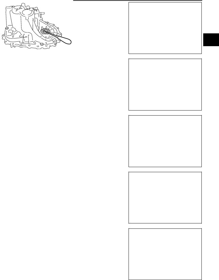
2.Stop the engine. Remove drain plug and drain oil.
3.Set a gasket on the drain plug and install it to the transaxle.
Drain plug:
 : 30 - 39 N·m (3.1 - 3.9 kg-m, 23 - 28 ft-lb)
CAUTION:
Do not reuse gasket.
FILLING
1.Remove filler plug. Fill with new oil until oil level reaches the specified limit near filler plug mounting hole.
Oil grade |
: API GL-4 |
Capacity (reference) |
: Approx. 2.3 (4 lmp pt) |
2.After refilling oil, check oil level. Assemble gasket to filler plug, then install it to transaxle body.
Filler plug:
 : 30 - 39 N·m (3.1 - 3.9 kg-m, 23 - 28 ft-lb)
CAUTION:
Do not reuse gasket.
Checking M/T Oil
OIL LEAKAGE AND OIL LEVEL
●Check that oil is not leaking from transaxle or around it.
●Check oil level from filler plug mounting hole as shown in the figure.
CAUTION:
Never start engine while checking oil level.
●Set a new gasket on the filler plug and install it on the transaxle.
Filler plug:
 : 30 - 39 N·m (3.1 - 3.9 kg-m, 23 - 28 ft-lb)
CAUTION:
Do not reuse gasket.
ECS008BS
SCIA0361E
MT-10
|
SIDE OIL SEAL |
|
|
SIDE OIL SEAL |
PFP:32113 |
Removal and Installation |
ECS008BT |
REMOVAL |
|
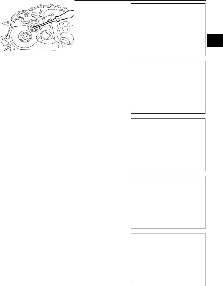
●Clutch housing side oil seal used on 4WD vehicles is attached to the transfer. Be sure to replace it when transfer is removed.
1.Remove the drive shaft from the transaxle.
2.Remove oil seal with flat tip screwdriver.
CAUTION:
Be careful not to damage the case surface when removing the oil seal.
SCIA0824E
A
B
MT
D
E
F
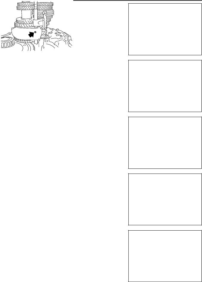
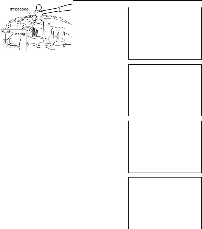
INSTALLATION
1.Using a drift (special service tool), drive the oil seal straight until it protrudes from the case end equal to dimension A shown in the figure.
Dimension "A":
Within 0.5 mm (0.020 in) of flush with the case.
Drift to be used: |
|
Transaxle case side: |
ST30720000 |
Clutch housing side: |
ST30720000 |
CAUTION:
●When installing oil seals, apply multi-purpose grease to oil seal lips.
●Oil seals are not reusable. Never reuse them.
2.Install all parts in reverse order of removal and check oil level after installation.
G
H
I
SCIA0352E
J
K
L
M
MT-11

POSITION SWITCH
POSITION SWITCH
Checking
BACK-UP LAMP SWITCH
PFP:32005
ECS008BU
● Check continuity.
Gear position |
Continuity |
|
|
Reverse |
Yes |
|
|
Except reverse |
No |
|
|
SCIA0708E
PARK/NEUTRAL POSITION SWITCH
● Check continuity.
Gear position |
Continuity |
|
|
Neutral |
Yes |
|
|
Except neutral |
No |
|
|
MT-12
CONTROL LINKAGE
CONTROL LINKAGE |
PFP:34103 |
|||
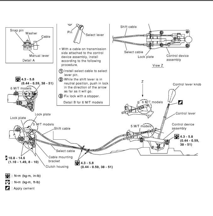
Removal and Installation of Control Device and Cable |
|
|
A |
|
ECS008BV |
||||
Refer to the figure for removal and installation procedure. |
|
|
|
|
|
|
|
|
B |
|
|
|
|
|
|
|
|
|
|
|
|
|
|
MT |
|
|
|
|
|
|
|
|
|
D |
|
|
|
|
E |
|
|
|
|
F |
|
|
|
|
G |
|
|
|
|
H |
|
|
|
|
I |
|
|
|
|
J |
|
|
|
|
K |
|
|
|
|
L |
|
|
|
|
M |
|
|
SCIA0711E |
|
|
CAUTION: |
|
|
|
|
●Keep in mind that the select side lock plate for securing the control cable is different from the one on the shift side.
●After assembly, make sure selector lever automatically returns to Neutral when it is moved to 1st, 2nd, or Reverse.
MT-13
AIR BREATHER HOSE |
|
|
|
AIR BREATHER HOSE |
PFP:31098 |
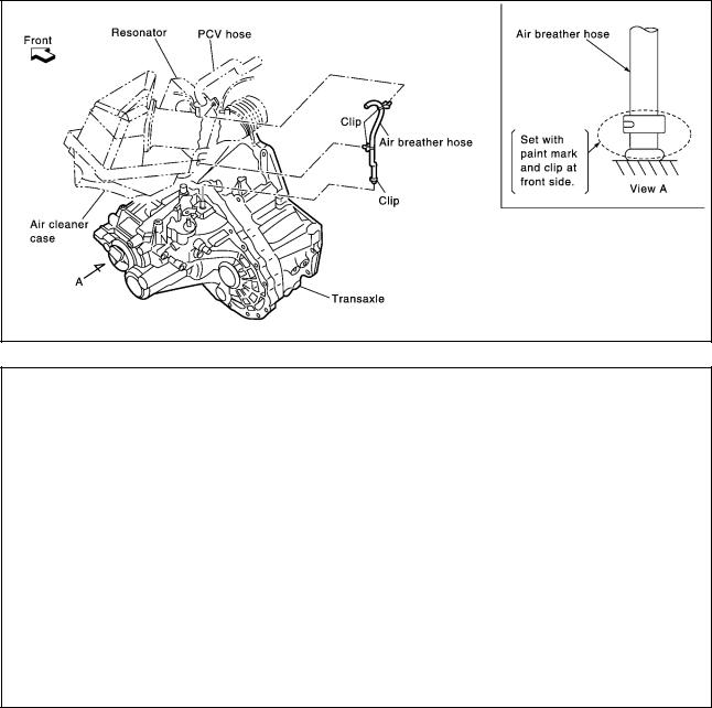
Removal and Installation |
ECS008BW |
Refer to the figure for air breather hose removal and installation information. |
|
QR engine models |
|
SCIA0354E
YD engine models
SCIA0747E
CAUTION:
●Make sure there are no pinched or restricted areas on the air breather hose caused by bending or winding when installing it.
●Be sure to insert hose into the transaxle tube until overlap area reaches the spool.
MT-14
TRANSAXLE ASSEMBLY
TRANSAXLE ASSEMBLY
Removal and Installation
PFP:32010
A
ECS008BX
B
MT
D
E
F
G
H
I
SCIA0845E
REMOVAL
1.Remove air cleaner, air duct, and battery.
2.Remove the air breather hose.
3.Remove clutch operating cylinder.
CAUTION:
Do not depress clutch pedal during removal procedure.
4.Disconnect control cable from transaxle.
5.Drain gear oil from transaxle.
6.Disconnect PNP switch, back-up lamp switch, and ground harness connectors.
7.Remove exhaust front tube and the drive shaft.
8.Remove transfer.
●Refer to TF-11, "Removal and Installation from Vehicle" .
9.Remove starter motor.
10.Place a jack onto the transaxle.
CAUTION:
When setting jack, be careful not to bring it into contact with the switch.
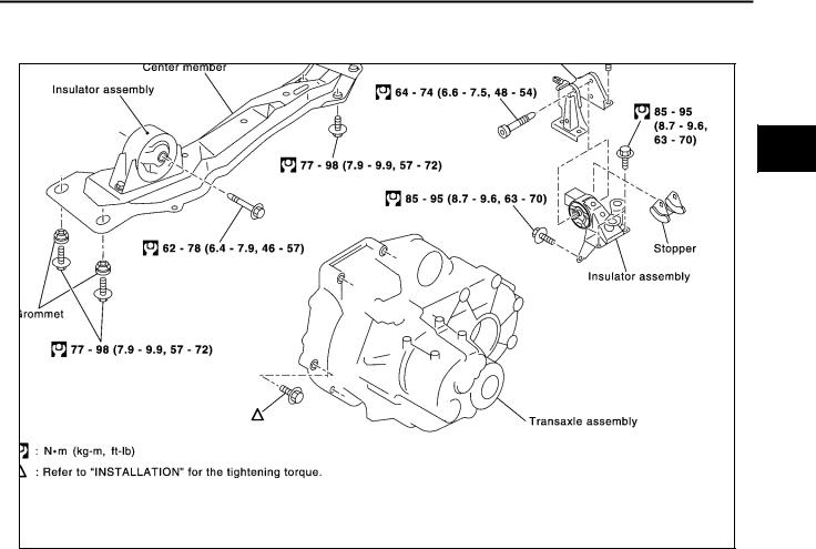
11.Remove center member, engine insulator and engine mount bracket.
●Refer to EM-69, "ENGINE ASSEMBLY" (QR engine models) or EM-193, "ENGINE ASSEMBLY" (YD engine models).
12.Remove suspension members.
●Refer to FSU-12, "FRONT SUSPENSION MEMBER" .
13.Support engine by placing a jack under oil pan.
14.Remove bolts securing transaxle to engine.
J
K
L
M
MT-15

TRANSAXLE ASSEMBLY
15. Remove transaxle from vehicle.
MTD0062D
INSTALLATION
Paying attention to the following items, install in the reverse order of removal.
●When installing the transaxle to the engine, tighten to the specified torque.
CAUTION:
When installing transaxle, be careful not to bring transaxle input shaft into contact with the clutch cover.
QR engine models:
Bolt No. |
1 |
|
2 |
|
3* |
4 |
5 |
6 |
|
|
|
|
|
|
|
|
|
Quantity |
2 |
|
1 |
|
1 |
2 |
2 |
2 |
|
|
|
|
|
|
|
|
|
“ ” mm (in) |
40 |
|
75 |
|
45 |
40 |
30 |
40 |
(1.57) |
(2.95) |
|
(1.77) |
(1.57) |
(1.18) |
(1.57) |
||
|
|
|||||||
|
|
|
|
|
|
|
|
|
Tightening torque |
|
|
69.6 - 79.4 |
|
39.2 - 46.1 |
30.4 - 40.2 |
||
|
|
|
(3.1 - 4.1, |
|||||
N·m (kg - m, ftlb) |
|
(7.1 - 8.1, 52 - 58) |
(4.0 - 4.7, 29 - 34) |
|||||
|
23 - 29) |
|||||||
|
|
|
|
|
|
|
|
|
|
|
|
|
|
|
|
|
|
*: Tightening the bolt for 4WD models.
SCIA0353E
YD engine models:
Bolt No. |
1 |
2 |
3 |
4 |
5 |
|
6 |
|
|
|
|
|
|
|
|
Quantity |
2 |
2 |
1 |
1 |
3 |
|
1 |
|
|
|
|
|
|
|
|
“ ” mm (in) |
55 |
70 |
120 |
45 |
40 |
|
35 |
(2.17) |
(2.76) |
(4.72) |
(1.77) |
(1.57) |
|
(1.38) |
|
|
|
||||||
|
|
|
|
|
|
|
|
Tightening torque |
|
40 - 49 |
|
|
31 - 36 |
||
N·m (kg - m, ftlb) |
|
(4.0 - 5.0, 29 - 36) |
|
(3.1 - 3.7, 23 - 26) |
|||
|
|
|
|
|
|
|
|
●After installation, check oil level, and look for leaks and loose mechanisms.
SCIA0748E
MT-16
TRANSAXLE ASSEMBLY
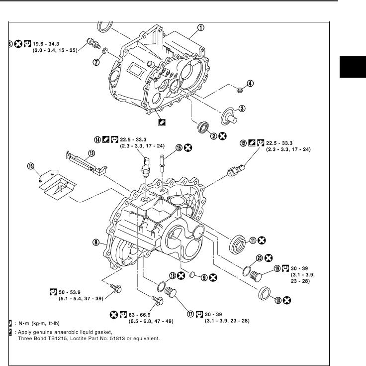
Component Parts (RS5F51A) |
ECS008BY |
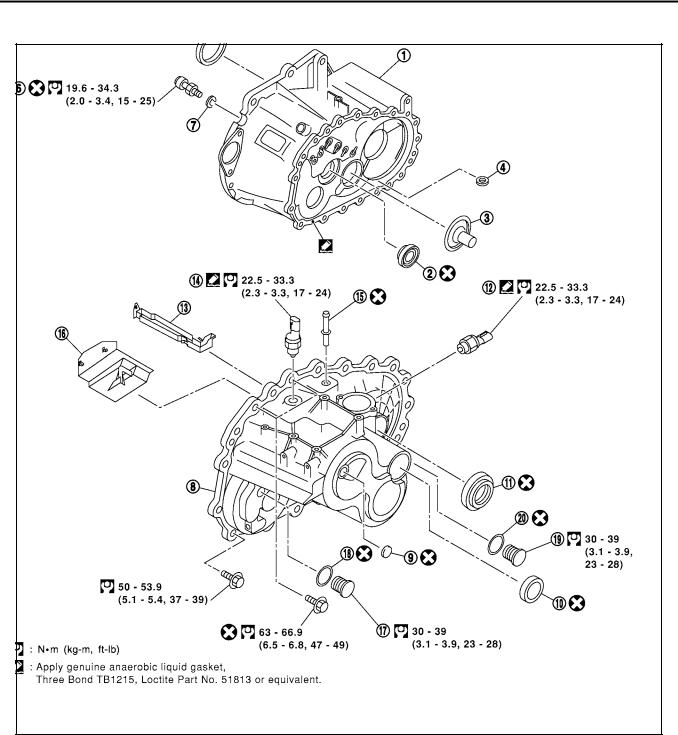
CASE AND HOUSING COMPONENTS |
A |
B
MT
D
E
F
G
H
I
J
K
L
M
SCIA1112E
1. |
Clutch housing |
2. |
Input shaft oil seal |
3. |
Oil channel |
4. |
Magnet |
5. |
Differential oil seal |
6. |
Ball pin |
7. |
Washer |
8. |
Transaxle case |
9. |
Welch plug |
10. |
Bore plug |
11. |
Differential oil seal |
12. |
Park/Neutral position switch |
13. |
Oil gutter |
14. |
Back-up lamp switch |
15. |
Air breather tube |
16. |
Baffle plate |
17. |
Filler plug |
18. |
Gasket |
19. |
Drain plug |
20. |
Gasket |
|
|
MT-17
TRANSAXLE ASSEMBLY
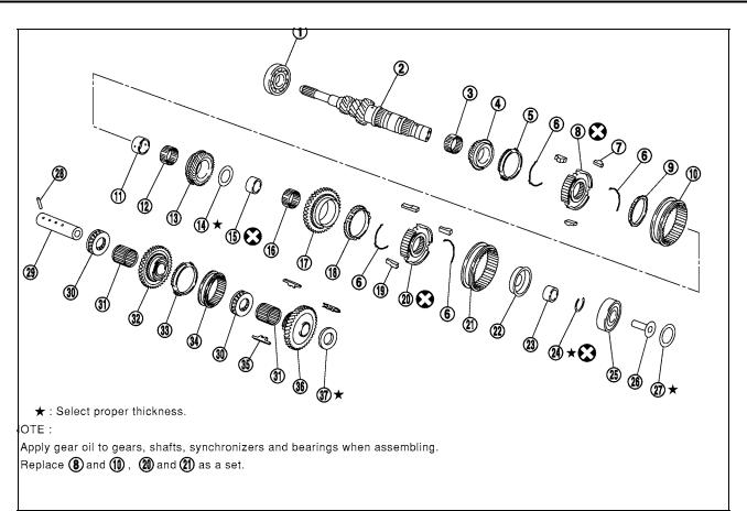
GEAR COMPONENTS
SCIA0385E
1. |
Input shaft front bearing |
2. |
Input shaft |
3. |
Needle bearing |
4. |
3rd input gear |
5. |
3rd baulk ring |
6. |
Spread spring |
7. |
3rd & 4th shifting insert |
8. |
3rd & 4th synchronizer hub |
9. |
4th baulk ring |
10. |
3rd & 4th coupling sleeve |
11. |
Bushing |
12. |
Needle bearing |
13. |
4th input gear |
14. |
Thrust washer |
15. |
Bushing |
16. |
Needle bearing |
17. |
5th input gear |
18. |
5th baulk ring |
19. |
5th shifting insert |
20. |
5th synchronizer hub |
21. |
5th coupling sleeve |
22. |
5th stopper |
23. |
Input shaft bearing spacer |
24. |
Snap ring |
25. |
Input shaft rear bearing |
26. |
Oil channel |
27. |
Input shaft rear bearing adjusting |
|
|
|
|
|
shim |
28. |
Retaining pin |
29. |
Reverse idler shaft |
30. |
Thrust needle bearing |
31. |
Needle bearing |
32. |
Reverse idler gear (Front) |
33. |
Reverse baulk ring |
34. |
Reverse coupling sleeve |
35. |
Insert spring |
36. |
Reverse idler gear (Rear) |
37. |
Reverse idler gear adjusting shim |
|
|
|
|
MT-18
TRANSAXLE ASSEMBLY
|
|
|
|
|
SCIA0386E |
1. |
Mainshaft front bearing |
2. |
Mainshaft bearing retainer |
3. |
Mainshaft |
4. |
Reverse main gear |
5. |
1st main gear |
6. |
Bushing |
7. |
Needle bearing |
8. |
1st inner baulk ring |
9. |
1st gear synchronizer cone |
10. |
1st outer baulk ring |
11. |
Spread spring |
12. |
1st & 2nd shifting insert |
13. |
1st & 2nd synchronizer hub |
14. |
2nd outer baulk ring |
15. |
2nd gear synchronizer cone |
16. |
2nd inner baulk ring |
17. |
1st &2nd coupling sleeve |
18. |
Bushing |
19. |
Needle bearing |
20. |
2nd main gear |
21. |
3rd main gear |
22. |
3rd &4th mainshaft spacer |
23. |
4th main adjusting shim |
24. |
4th main gear |
25. |
5th main gear |
26. |
Snap ring |
27. |
Mainshaft rear bearing |
28. |
Mainshaft C ring |
29. |
C ring holder |
30. |
Snap ring |
31. |
Snap ring |
32. |
Mainshaft rear bearing adjusting shim |
|
|
A
B
MT
D
E
F
G
H
I
J
K
L
M
MT-19
TRANSAXLE ASSEMBLY
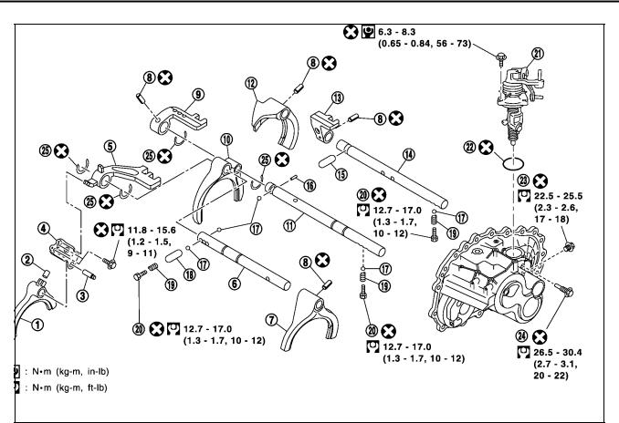
SHIFT CONTROL COMPONENTS
SCIA0387E
1. |
Reverse shift fork |
2. |
Shifter cap |
3. |
Reverse fork rod |
4. |
Reverse lever assembly |
5. |
5th & reverse bracket |
6. |
5th & reverse fork rod |
7. |
5th shift fork |
8. |
Retaining pin |
9. |
3rd & 4th bracket |
10. |
3rd & 4th shift fork |
11. |
3rd & 4th fork rod |
12. |
1st & 2nd shift fork |
13. |
1st & 2nd bracket |
14. |
1st & 2nd fork rod |
15. |
Shift check sleeve |
16. |
Inter lock pin |
17. |
Check ball |
18. |
Shift check sleeve |
19. |
Check spring |
20. |
Check plug |
21. |
Control assembly |
22. |
O ring |
23. |
Shift check |
24. |
Stopper bolt |
25. |
Stopper ring |
|
|
|
|
MT-20
TRANSAXLE ASSEMBLY
FINAL DRIVE COMPONENTS
|
|
|
|
|
SCIA0388E |
1. |
Differential side bearing outer race |
2. |
Differential side bearing |
3. |
Differential case |
4. |
Final gear |
5. |
Differential side bearing |
6. |
Differential side bearing outer race |
7. |
Differential side bearing adjusting |
8. |
Pinion mate shaft |
9. |
Side gear |
|
shim |
|
|
|
|
10. |
Side gear thrust washer |
11. |
Pinion mate gear |
12. |
Pinion mate gear washer |
13. |
Retaining pin |
|
|
|
|
A
B
MT
D
E
F
G
H
I
J
K
L
M
MT-21
TRANSAXLE ASSEMBLY
Component Parts (RS6F51A) |
ECS008BZ |
CASE AND HOUSING COMPONENTS
SCIA1112E
1. |
Clutch housing |
2. |
Input shaft oil seal |
3. |
Oil channel |
4. |
Magnet |
5. |
Differential oil seal |
6. |
Ball pin |
7. |
Washer |
8. |
Transaxle case |
9. |
Welch plug |
10. |
Bore plug |
11. |
Differential oil seal |
12. |
Park/Neutral position switch |
13. |
Oil gutter |
14. |
Back-up lamp switch |
15. |
Air breather tube |
16. |
Baffle plate |
17. |
Filler plug |
18. |
Gasket |
19. |
Drain plug |
20. |
Gasket |
|
|
MT-22
TRANSAXLE ASSEMBLY
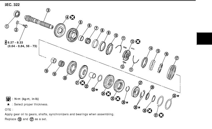
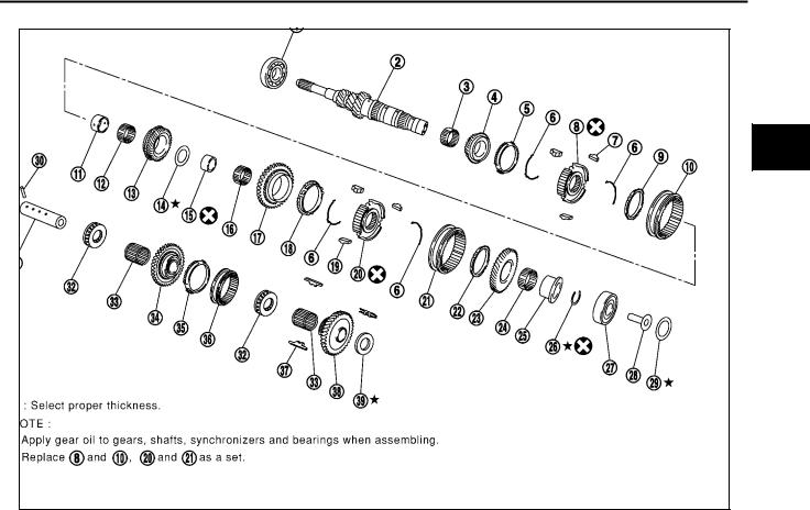
GEAR COMPONENTS
SCIA0956E
1. |
Input shaft front bearing |
2. |
Input shaft |
3. |
Needle bearing |
4. |
3rd input gear |
5. |
3rd baulk ring |
6. |
Spread spring |
7. |
3rd & 4th shifting insert |
8. |
3rd & 4th synchronizer hub |
9. |
4th baulk ring |
10. |
3rd & 4th coupling sleeve |
11. |
Bushing |
12. |
Needle bearing |
13. |
4th input gear |
14. |
Thrust washer |
15. |
Bushing |
16. |
Needle bearing |
17. |
5th input gear |
18. |
5th baulk ring |
19. |
5th & 6th shifting insert |
20. |
5th & 6th synchronizer hub |
21. |
5th & 6th coupling sleeve |
22. |
6th baulk ring |
23. |
6th input gear |
24. |
Needle bearing |
25. |
Bushing |
26. |
Snap ring |
27. |
Input shaft rear bearing |
28. |
Oil channel |
29. |
Input shaft rear bearing adjusting |
30. |
Retaining pin |
|
|
|
shim |
|
|
31. |
Reverse idler shaft |
32. |
Thrust needle bearing |
33. |
Needle bearing |
34. |
Reverse idler gear (Front) |
35. |
Reverse baulk ring |
36. |
Reverse coupling sleeve |
37. |
Insert spring |
38. |
Reverse idler gear (Rear) |
39. |
Reverse idler gear adjusting shim |
A
B
MT
D
E
F
G
H
I
J
K
L
M
MT-23
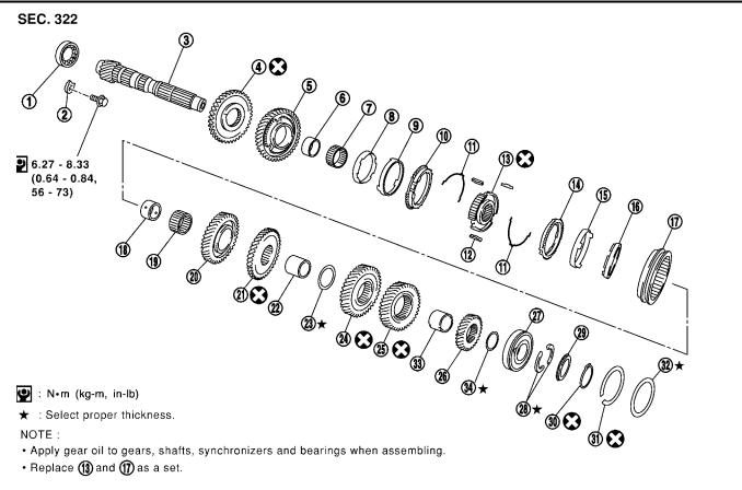
TRANSAXLE ASSEMBLY
|
|
|
|
|
SCIA0957E |
1. |
Mainshaft front bearing |
2. |
Mainshaft bearing retainer |
3. |
Mainshaft |
4. |
Reverse main gear |
5. |
1st main gear |
6. |
Bushing |
7. |
Needle bearing |
8. |
1st inner baulk ring |
9. |
1st gear synchronizer cone |
10. |
1st outer baulk ring |
11. |
Spread spring |
12. |
1st & 2nd shifting insert |
13. |
1st & 2nd synchronizer hub |
14. |
2nd outer baulk ring |
15. |
2nd gear synchronizer cone |
16. |
2nd inner baulk ring |
17. |
1st & 2nd coupling sleeve |
18. |
Bushing |
19. |
Needle bearing |
20. |
2nd main gear |
21. |
3rd main gear |
22. |
3rd & 4th mainshaft spacer |
23. |
4th main adjusting shim |
24. |
4th main gear |
25. |
5th main gear |
26. |
6th main gear |
27. |
Mainshaft rear bearing |
28. |
Mainshaft C ring |
29. |
C ring holder |
30. |
Snap ring |
31. |
Snap ring |
32. |
Mainshaft rear bearing adjusting shim |
33. |
5th & 6th mainshaft spacer |
34. |
6th main adjusting shim |
|
|
|
|
MT-24
TRANSAXLE ASSEMBLY
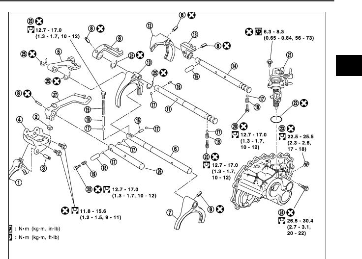
SHIFT CONTROL COMPONENTS
A
B
MT
D
E
F
G
H
I
J
|
|
|
|
|
|
SCIA0958E |
|
1. |
Reverse shift fork |
2. |
Shifter cap |
3. |
Reverse fork rod |
|
|
4. |
Reverse lever assembly |
5. |
5th & 6th bracket |
6. |
5th & 6th fork rod |
|
K |
7. |
5th & 6th shift fork |
8. |
Retaining pin |
9. |
3rd & 4th bracket |
|
|
10. |
3rd & 4th shift fork |
11. |
3rd & 4th fork rod |
12. |
1st & 2nd shift fork |
|
|
13. |
1st & 2nd fork rod bracket |
14. |
1st & 2nd fork rod |
15. |
Shift check sleeve |
|
L |
16. |
Inter lock pin |
17. |
Check ball |
18. |
Shift check sleeve |
|
|
19. |
Check spring |
20. |
Check plug |
21. |
Control assembly |
|
|
22. |
O ring |
23. |
Shift check |
24. |
Stopper bolt |
|
M |
25. |
Stopper ring |
26. |
Reverse bracket fork rod |
27. |
Reverse bracket |
|
|
MT-25
TRANSAXLE ASSEMBLY
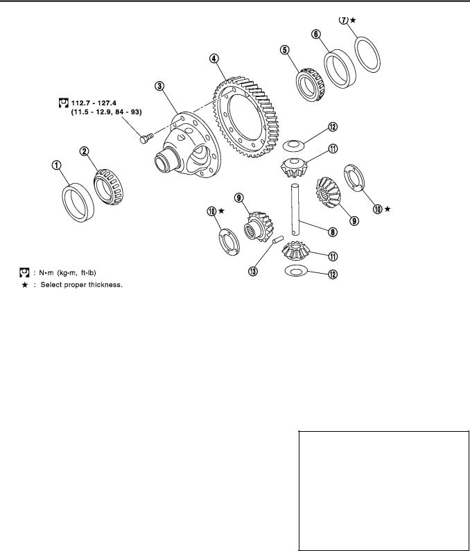
FINAL DRIVE COMPONENTS
|
|
|
|
|
|
SCIA0388E |
|
1. |
Differential side bearing outer race |
2. |
Differential side bearing |
3. |
Differential case |
||
4. |
Final gear |
5. |
Differential side bearing |
6. |
Differential side bearing outer race |
||
7. |
Differential side bearing adjusting shim |
8. |
Pinion mate shaft |
9. |
Side gear |
||
10. |
Side gear thrust washer |
11. |
Pinion mate gear |
12. |
Pinion mate gear washer |
||
13. |
Retaining pin |
|
|
|
|
|
|
Disassembly and Assembly (RS5F51A) |
|
ECS008C0 |
|||||
DISASSEMBLY
1.Remove drain plug and filler plug.
2.Remove park/neutral position switch and back-up lamp switch.
3.After removing shift check and stopper bolt, remove control assembly.
SCIA0389E
MT-26
TRANSAXLE ASSEMBLY
4.Remove check plugs (3 pieces), check springs (3 pieces), check balls (3 pieces) and shift check sleeve (1 piece).
5.Remove transaxle case fixing bolts.
6.Remove bore plug.
CAUTION:
Be careful not to damage transaxle case.
7.While spreading the snap ring of mainshaft rear bearing located at bore plug hole, remove transaxle case.
8.Remove oil gutter, baffle plate.
9.Remove snap ring, mainshaft rear bearing adjusting shim and input shaft rear bearing adjusting shim from transaxle case.
10.Remove differential side bearing outer race (transaxle case side) and then adjust shim.
11. Remove welch plug.
12.Remove differential oil seal (tansaxle case side).
13.Remove magnet from clutch housing.
SCIA0396E
SCIA0983E
SCIA0897E
SCIA0402E
SCIA0397E
A
B
MT
D
E
F
G
H
I
J
K
L
M
MT-27
TRANSAXLE ASSEMBLY
14.With shift lever in 5th position, remove bracket bolts from reverse lever assembly. Lift reverse lever assembly to remove.
CAUTION:
Be careful not to lose shifter cap.
15.Pull out reverse fork rod then remove reverse shift fork.
SCIA0390E
16.Shift 3rd & 4th fork rod to 3rd position. Remove retaining pin of 5th shift fork using pin punch.
SCIA0391E
17.Remove stopper rings for 5th & reverse bracket.
18.Pull out 5th & reverse fork rod and remove 5th shift fork and 5th & reverse bracket.
19.Remove check balls (2 pieces) and inter lock pin.
SCIA0392E
20.Remove retaining pin of 3rd & 4th bracket using pin punch.
21.Remove stopper rings for 3rd & 4th shift fork.
22.Pull out 3rd & 4th fork rod and remove 3rd & 4th shift fork and bracket.
23.Remove shift check sleeve from clutch housing.
SCIA0393E
24.Remove retaining pin of 1st & 2nd shift fork using pin punch.
25.Pull out 1st & 2nd fork rod with bracket.
26.Remove 1st & 2nd shift fork.
27.Remove retaining pin of 1st & 2nd bracket using pin punch and separate 1st & 2nd fork rod and bracket.
SCIA0394E
MT-28
TRANSAXLE ASSEMBLY
28.Remove gear components from clutch housing in the following procedure.
a.While tapping input shaft with plastic hammer, remove input shaft assembly, mainshaft assembly and reverse idler gear assembly as a set.
CAUTION:
Always withdraw mainshaft straight out. Failure to do so can damage resin oil channel on clutch housing side.
b.Remove final drive assembly.
29.Remove bearing retainer and then mainshaft front bearing.
30.Remove oil channel on mainshaft side.
31. Remove differential oil seal (clutch housing side).
32.Remove differential side bearing outer race (clutch housing side).
33.Remove input shaft oil seal.
CAUTION:
Be careful not to damage clutch housing.
SCIA0395E
SCIA1077J
SCIA1068J
SCIA1069J
SCIA0398E
A
B
MT
D
E
F
G
H
I
J
K
L
M
MT-29
TRANSAXLE ASSEMBLY
ASSEMBLY
1.Using a drift, install input shaft oil seal from clutch housing end of side to the depth of 1.8 to 2.8 mm (0.071 to 0.110 in).
CAUTION:
Do not reuse oil seals.
SCIA0399E
2.Using a drift, install differential oil seal until the face is flush with clutch housing.
CAUTION:
Do not reuse oil seals.
SCIA1070J
3.Install oil channel on mainshaft side.
CAUTION:
Be careful with orientation of installation.
SCIA0986E
4.Using a drift, install mainshaft front bearing.
CAUTION:
Be careful with orientation of installation.
SCIA0401E
MT-30
Loading...