


 Loading...
K ELECTRICAL
SECTION SC
STARTING & CHARGING SYSTEM
CONTENTS
A
B
C
D
E
PRECAUTIONS ......................................................... |
2 |
Precautions for Supplemental Restraint System |
|
(SRS) “AIR BAG” and “SEAT BELT PRE-TEN- |
|
SIONER” ................................................................. |
2 |
Wiring Diagrams and Trouble Diagnosis ................. |
2 |
PREPARATION .......................................................... |
3 |
Special Service Tools .............................................. |
3 |
Commercial Service Tools ....................................... |
3 |
BATTERY ................................................................... |
4 |
How to Handle Battery ............................................ |
4 |
METHODS OF PREVENTING OVER-DIS- |
|
CHARGE .............................................................. |
4 |
CHECKING ELECTROLYTE LEVEL ................... |
5 |
SPECIFIC GRAVITY CHECK .............................. |
5 |
CHARGING THE BATTERY ................................ |
6 |
Trouble Diagnoses with Battery/Starting/Charging |
|
System Tester ......................................................... |
6 |
DIAGNOSTIC RESULT ITEM CHART ................. |
8 |
Removal and Installation ......................................... |
8 |
STARTING SYSTEM ................................................. |
9 |
System Description ................................................. |
9 |
M/T MODELS ....................................................... |
9 |
A/T MODELS ....................................................... |
9 |
Wiring Diagram — START — / M/T Models ........ |
... 10 |
Wiring Diagram — START — / A/T Models ......... |
....11 |
Trouble Diagnoses with Battery/Starting/Charging |
|
System Tester ....................................................... |
12 |
DIAGNOSTIC RESULT ITEM CHART ............... |
12 |
WORK FLOW ..................................................... |
13 |
DIAGNOSTIC PROCEDURE 1 .......................... |
14 |
DIAGNOSTIC PROCEDURE 2 .......................... |
15 |
MINIMUM SPECIFICATION OF CRANKING |
|
VOLTAGE REFERENCING COOLANT TEM- |
|
PERATURE ........................................................ |
15 |
Removal and Installation ....................................... |
16 |
M/T MODELS ..................................................... |
16 |
A/T MODELS ...................................................... |
17 |
Disassembly and Assembly ................................... |
18 |
M/T MODELS ..................................................... |
18 |
A/T MODELS ...................................................... |
19 |
INSPECTION AFTER DISASSEMBLY ............... |
19 |
CHARGING SYSTEM .............................................. |
20 |
System Description ................................................ |
20 |
DESCRIPTION ................................................... |
20 |
MALFUNCTION INDICATOR ............................. |
20 |
Wiring Diagram — CHARGE — .......................... |
... 21 |
Trouble Diagnoses with Battery/Starting/Charging |
|
System Tester ........................................................ |
22 |
DIAGNOSTIC RESULT ITEM CHART ............... |
23 |
WORK FLOW ..................................................... |
24 |
PRELIMINARY INSPECTION ............................ |
25 |
DIAGNOSTIC PROCEDURE 1 .......................... |
26 |
DIAGNOSTIC PROCEDURE 2 .......................... |
26 |
DIAGNOSTIC PROCEDURE 3 .......................... |
27 |
DIAGNOSTIC PROCEDURE 4 .......................... |
28 |
Removal and Installation ....................................... |
29 |
REMOVAL .......................................................... |
29 |
ALTERNATOR PULLEY INSPECTION .............. |
29 |
INSTALLATION .................................................. |
30 |
Disassembly and Assembly ................................... |
30 |
DISASSEMBLY FOR ALTERNATOR PULLEY |
... 30 |
ASSEMBLY FOR ALTERNATOR PULLEY ........ |
31 |
SERVICE DATA AND SPECIFICATIONS (SDS) ..... |
32 |
Battery ................................................................... |
32 |
Starter .................................................................... |
32 |
Alternator ............................................................... |
32 |
F
G
H
I
J
SC
L
M
Revision: 2005 March |
SC-1 |
2005 X-Trail |
|
PRECAUTIONS |
|
|
PRECAUTIONS |
PFP:00011 |
Precautions for Supplemental Restraint System (SRS) “AIR BAG” and “SEAT BELT PRE-TENSIONER” AKS00B6K
The Supplemental Restraint System such as “AIR BAG” and “SEAT BELT PRE-TENSIONER”, used along with a front seat belt, helps to reduce the risk or severity of injury to the driver and front passenger for certain types of collision. Information necessary to service the system safely is included in the SRS and SB section of this Service Manual.
WARNING:
●To avoid rendering the SRS inoperative, which could increase the risk of personal injury or death in the event of a collision which would result in air bag inflation, all maintenance must be performed by an authorized NISSAN/INFINITI dealer.
●Improper maintenance, including incorrect removal and installation of the SRS, can lead to personal injury caused by unintentional activation of the system. For removal of Spiral Cable and Air Bag Module, see the SRS section.
●Do not use electrical test equipment on any circuit related to the SRS unless instructed to in this Service Manual. SRS wiring harnesses can be identified by yellow and/or orange harnesses or harness connectors.
Wiring Diagrams and Trouble Diagnosis |
AKS00B6L |
When reading wiring diagrams, refer to the following:
●GI-14, "How to Read Wiring Diagrams" in GI section
●PG-2, "POWER SUPPLY ROUTING" for power distribution circuit in PG section When performing trouble diagnosis, refer to the following:
●GI-10, "HOW TO FOLLOW TEST GROUPS IN TROUBLE DIAGNOSES" in GI section
●GI-26, "How to Perform Efficient Diagnosis for an Electrical Incident" in GI section
Revision: 2005 March |
SC-2 |
2005 X-Trail |

PREPARATION
PREPARATION |
|
|
PFP:00002 |
||
Special Service Tools |
|
|
|
A |
|
|
|
AKS00B6M |
|||
|
|
|
|
|
|
|
Tool number |
|
|
|
B |
|
(Kent-Moore No.) |
|
Description |
|
|
|
Tool name |
|
|
|
|
|
|
|
|
|
|
|
KV10118200 |
|
Removing alternator pulley |
|
|
|
( — ) |
|
|
|
C |
|
Alternator pulley adapter |
|
|
|
|
|
|
|
|
|
D |
|
|
PKIA1241E |
|
|
|
|
|
|
|
|
|
|
— |
|
|
|
E |
|
(J-44373 Model 620) |
|
|
|
|
|
Battery/Starting/Charging system |
|
|
|
|
|
tester |
|
|
|
F |
|
|
|
|
|
|
|
|
SEL403X |
|
|
G |
|
|
|
|
|
|
|
|
|
|
|
H |
|
|
|
|
|
|
Commercial Service Tools
AKS00BHE I
Tool number |
Description |
|
Tool name |
||
|
|
|
|
J |
Power tool |
Loosening bolts and nuts |
||
|
|
|
|
|
|
|
SC |
|
|
|
|
PBIC0190E |
|
|
L |
|
|
|
M |
|
|
|
|
Revision: 2005 March |
SC-3 |
2005 X-Trail |
|
BATTERY |
|
|
BATTERY |
PFP:00011 |
How to Handle Battery |
AKS00BHF |
CAUTION:
●If it becomes necessary to start the engine with a booster battery and jumper cables, use a 12-volt booster battery.
●After connecting battery cables, ensure that they are tightly clamped to battery terminals for good contact.
METHODS OF PREVENTING OVER-DISCHARGE
The following precautions must be taken to prevent over-discharging a battery.
●The battery surface (particularly its top) should always be kept clean and dry.
●
●
The terminal connections should be clean and tight.
At every routine maintenance, check the electrolyte level.
This also applies to batteries designated as “low maintenance” and “maintenance-free”.
MEL040F
●When the vehicle is not going to be used over a long period of time, disconnect battery cable at negative terminal.
ELA0349D
●Check the charge condition of the battery.
Periodically check the specific gravity of the electrolyte. Keep a close check on charge condition to prevent over-discharge.
MEL042F
Revision: 2005 March |
SC-4 |
2005 X-Trail |

BATTERY
CHECKING ELECTROLYTE LEVEL
WARNING:
Do not allow battery fluid to come in contact with skin, eyes, fabrics, or painted surfaces. After touching a battery, do not touch or rub your eyes until you have thoroughly washed your hands. If acid contacts eyes, skin or clothing, immediately flush with water for 15 minutes and seek medical attention.
●Remove the cell plug using a suitable tool.
●Add distilled water up to the MAX level.
MEL043F
A
B
C
D
E
Sulphation
A battery will be completely discharged if it is left unattended for a long time and the specific gravity will become less than 1.100. This may result in sulphation on the cell plates.
To determine if a battery has been “sulphated”, note its voltage and current when charging it. As shown in the figure, less current and higher voltage are observed in the initial stage of charging sulphated batteries.
A sulphated battery may sometimes be brought back into service by means of a long, slow charge, 12 hours or more, followed by a battery capacity test.
F
G
H
I
PKIA2353E
SPECIFIC GRAVITY CHECK
1.Read hydrometer and thermometer indications at eye level.
2.Use the chart below to correct your hydrometer reading according to electrolyte temperature.
J
SC
L
MEL042FA M
Hydrometer Temperature Correction
Battery electrolyte temperature ° C (° F) |
Add to specific gravity reading |
|
|
71 (160) |
0.032 |
|
|
66 (150) |
0.028 |
|
|
60 (140) |
0.024 |
|
|
54 (130) |
0.020 |
|
|
49 (120) |
0.016 |
|
|
43 (110) |
0.012 |
|
|
38 (100) |
0.008 |
|
|
32 (90) |
0.004 |
|
|
27 (80) |
0 |
|
|
21 (70) |
− 0.004 |
|
|
Revision: 2005 March |
SC-5 |
2005 X-Trail |

BATTERY
Battery electrolyte temperature ° C (° F) |
Add to specific gravity reading |
||
|
|
|
|
16 |
(60) |
− |
0.008 |
|
|
|
|
10 |
(50) |
− |
0.012 |
|
|
|
|
4 (40) |
− |
0.016 |
|
|
|
|
|
− 1 |
(30) |
− |
0.020 |
|
|
|
|
− 7 |
(20) |
− |
0.024 |
|
|
|
|
− 12 (10) |
− |
0.028 |
|
|
|
|
|
− 18 (0) |
− |
0.032 |
|
|
|
||
|
|
||
Corrected specific gravity |
Approximate charge condition |
||
|
|
|
|
1.260 |
- 1.280 |
Fully charged |
|
|
|
|
|
1.230 |
- 1.250 |
3/4 charged |
|
|
|
|
|
1.200 |
- 1.220 |
1/2 charged |
|
|
|
|
|
1.170 |
- 1.190 |
1/4 charged |
|
|
|
|
|
1.140 |
- 1.160 |
Almost discharged |
|
|
|
|
|
1.110 |
- 1.130 |
Completely discharged |
|
|
|
|
|
CHARGING THE BATTERY
CAUTION:
●Do not “quick charge” a fully discharged battery.
●Keep the battery away from open flame while it is being charged.
●When connecting the charger, connect the leads first, then turn on the charger. Do not turn on the charger first, as this may cause a spark.
●If battery electrolyte temperature rises above 55 ° C (131 ° F), stop charging. Always charge battery at a temperature below 55 ° C (131 ° F).
Charging Rates
Amps |
Time |
|
|
50 |
1 hour |
|
|
25 |
2 hours |
|
|
10 |
5 hours |
|
|
5 |
10 hours |
|
|
Do not charge at more than 50 ampere rate.
NOTE:
The ammeter reading on your battery charger will automatically decrease as the battery charges. This indicates that the voltage of the battery is increasing normally as the state of charge improves. The charging amps indicated above refer to initial charge rate.
●If, after charging, the specific gravity of any two cells varies more than 0.050, the battery should be replaced.
Trouble Diagnoses with Battery/Starting/Charging System Tester |
AKS00BHG |
CAUTION:
When working with batteries, always wear appropriate eye protection.
NOTE:
●To ensure a complete and thorough diagnosis, the battery, starter and generator test segments must be done as a set from start to finish.
●If battery surface charge is detected while testing, the tester will prompt you to turn on the headlamps to remove the surface charge.
● If necessary, the tester will prompt you to determine if the battery temperature is above or below 0 ° C (32 ° F). Choose the appropriate selection by pressing the up or down arrow button, then press “ENTER” to make the selection.
Revision: 2005 March SC-6 2005 X-Trail

BATTERY
1.Turn off all loads on the vehicle electrical system. Clean or repair as necessary.
2.Visually inspect the battery, battery terminals and cable ends with ignition switch in “OFF” position.
NOTE:
The contact surface between the battery terminals, cable ends and tester leads must be clean for a valid test. A poor connection will prevent testing and a “CHECK CONNECTION” message will appear during the test procedures. If this occurs, clean the battery terminals, reconnect them and restart the test.
3.Connect the red tester lead clamp to the positive battery terminal, and the black to the negative battery terminal.
4.The tester will turn on automatically. Using the arrow keys, select “IN-VEHICLE” on the tester and then press the “ENTER” key.
5.Locate the battery type and rating stamped or written on the top case of the battery to be tested.
NOTE:
The battery type and rating will have either of the following. CCA: Cold Cranking Amps (490 CCA, 550 CCA, etc.)
JIS: Japanese Industrial Standard. Battery is stamped with a number such as:
80D26L: 80 (rank of output), D (physical size-depth), 26 (width in cm). The last character L (post configuration) is not input into the tester.
The tester requires the rating for the battery be entered exactly as it is written or stamped on the battery. Do not attempt a CCA conversion for JIS stamped batteries. JIS must be input directly.
6.Using the arrow and “ENTER” keys alternately, select the battery type and rating.
NOTE:
The tester lists five choices; CCA, JIS, IEC, DIN, and EN. Only use CCA or JIS.
7.Press “ENTER” to begin the test. Diagnosis results are displayed on the tester. Refer to SC-8, "DIAGNOSTIC RESULT ITEM CHART" .
A
B
C
SEL404X
D
E
F
G
SEL405X
H
I
J
SC
SEL406X
L
M
SEL407X
Revision: 2005 March |
SC-7 |
2005 X-Trail |

BATTERY
8.Press “ENTER”, then test output code is displayed. Record the test output code on the repair order.
9.Toggle back to the “DIAGNOSTIC SCREEN” for test results.
NOTE:
●If necessary, the tester will ask the user to determine if the battery has just been charged. Choose the appropriate selection by pressing the up or down arrow button and then press the “ENTER” button to make the selection.
●When testing a battery installed in a vehicle that has recently been driven, select “BEFORE CHARGE”.
SEL576X
● If the battery has just been slow charged due to a “CHARGE
& RETEST” decision by the tester, and the tester asks the user “BEFORE CHARGE/AFTER CHARGE”, select “AFTER CHARGE”.
DIAGNOSTIC RESULT ITEM CHART
Diagnostic item |
Service procedure |
|||
|
|
|||
GOOD BATTERY |
Battery is OK, go to “Trouble Diagnoses”, “STARTING SYSTEM”. Refer SCto -12, "Trouble |
|||
Diagnoses with Battery/Starting/Charging System Tester" . |
|
|
||
|
||||
|
|
|||
|
Replace battery. |
|||
REPLACE BATTERY |
Before replacing battery, clean the battery cable clamps and battery terminals. Perform bat- |
|||
tery test again with Battery/Starting/Charging system tester. If second test result is “Replace |
||||
|
||||
|
Battery”, then do so. Perform battery test again to confirm repair. |
|||
|
|
|||
BAD CELL-REPLACE |
Replace the battery. Perform battery test again with Battery/Starting/Charging system tester |
|||
to confirm repair. |
||||
|
||||
|
|
|||
GOOD-RECHARGE |
Perform the slow battery charging procedure. (Initial rate of charge is 10 A for 12 hours.) |
|||
|
|
|||
|
Perform the slow battery charging. (Initial rate of charge is 10 A for 12 hours.) |
|||
|
Perform battery test again with Battery/Starting/Charging system tester to confirm repair. |
|||
CHARGE & RETEST |
NOTE: |
|||
|
If the tester asks the user “BEFORE CHARGE/AFTER CHARGE”, select “AFTER |
|||
|
CHARGE”. |
|||
|
|
|
|
|
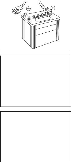
Removal and Installation
Observe the following to ensure proper servicing.
CAUTION:
●When removing, disconnect battery cable at negative terminal first. But for installation, connect battery cable to positive terminal first.
●Tighten parts to the specified torque shown below.
Battery fix frame mounting nut:
 : 4.4 N·m (0.45 kg-m, 39 in-lb)
Battery cable tightening nut:
 : 4.0 N·m (0.41 kg-m, 35 in-lb)
AKS00B6P
SKIA0068E
Revision: 2005 March |
SC-8 |
2005 X-Trail |

|
STARTING SYSTEM |
|
|
STARTING SYSTEM |
PFP:00011 |
System Description |
AKS00B6Z |
M/T MODELS |
|
Power is supplied at all times
●through 30A fusible link (letter J, located in the fuse and fusible link box)
●to ignition switch terminal 1.
With the ignition switch in the START position, power is supplied
●from ignition switch terminal 5
●to park/neutral position relay terminal 5.
With the ignition switch in the ON or START position, power is supplied
●through 10A fuse [No,13 located in the fuse block (J/B)]
●to park/neutral position relay terminal 1.
With the clutch interlock switch is depressed, ground is supplied
●to park/neutral position relay terminal 2
●through clutch interlock switch terminals 1 and 2, and
●through grounds M27 and M70.
Then park/neutral position relay is energized and power is supplied
●from park/neutral position relay terminal 3
●to starter motor harness connector terminal 1.
The starter motor plunger closes and provides a closed circuit between the battery and starter motor. The starter motor is grounded to engine block. With power and ground supplied, cranking occurs and the engine starts.
A/T MODELS
Power is supplied at all times
●through 30 A fusible link (letter J, located in fuse and fusible link box)
●to ignition switch terminal 1.
With the ignition switch in the START position, power is supplied
●from ignition switch terminal 5
●to park/neutral position relay terminal 5.
With the ignition switch in the ON or START position, power is supplied
●through 10 A fuse [No,13 located in the fuse block (J/B)]
●to park/neutral position relay terminal 1.
With the selector lever in the P or N position, ground is supplied
●to park/neutral position relay terminal 2
●through park/neutral position switch terminals 1 and 2, and
●through grounds F9 and F10.
Then park/neutral position relay is energized and power is supplied
●from park/neutral position relay terminal 3
●to starter motor harness connector terminal 1.
The starter motor plunger closes and provides a closed circuit between the battery and starter motor. The starter motor is grounded to engine block. With power and ground supplied, cranking occurs and the engine starts.
A
B
C
D
E
F
G
H
I
J
SC
L
M
Revision: 2005 March |
SC-9 |
2005 X-Trail |

STARTING SYSTEM
Wiring Diagram — START — / M/T Models
AKS00B70
TKWB0147E
Revision: 2005 March |
SC-10 |
2005 X-Trail |
Loading...