


 Loading...
K ELECTRICAL
SECTION LAN
LAN SYSTEM
CONTENTS
A
B
C
D
E
CAN |
|
PRECAUTIONS ......................................................... |
3 |
Precautions for Supplemental Restraint System |
|
(SRS) “AIR BAG” and “SEAT BELT PRE-TEN- |
|
SIONER” ................................................................. |
3 |
Precautions for Trouble Diagnosis .......................... |
3 |
CAN SYSTEM ...................................................... |
3 |
Precautions for Harness Repair .............................. |
3 |
CAN SYSTEM ...................................................... |
3 |
TROUBLE DIAGNOSES WORK FLOW ................... |
4 |
When Displaying CAN Communication System |
|
Errors ...................................................................... |
4 |
WHEN A MALFUNCTION IS DETECTED BY |
|
CAN COMMUNICATION SYSTEM ...................... |
4 |
WHEN A MALFUNCTION IS DETECTED |
|
EXCEPT CAN COMMUNICATION SYSTEM ....... |
4 |
TROUBLE DIAGNOSIS FLOW CHART .............. |
5 |
Diagnosis Procedure ............................................... |
6 |
SELECTING CAN SYSTEM TYPE (HOW TO |
|
USE SPECIFICATION TABLE) ............................ |
6 |
ACQUISITION OF DATA BY CONSULT-II ........... |
7 |
HOW TO USE CHECK SHEET TABLE ............... |
8 |
CAN Diagnostic Support Monitor .......................... |
13 |
DESCRIPTION OF “CAN DIAG SUPPORT |
|
MNTR” SCREEN FOR ECM .............................. |
13 |
DESCRIPTION OF “CAN DIAG SUPPORT |
|
MNTR” SCREEN FOR TCM .............................. |
14 |
DESCRIPTION OF “CAN DIAG SUPPORT |
|
MNTR” SCREEN FOR ABS ACTUATOR AND |
|
ELECTRIC UNIT (CONTROL UNIT) .................. |
14 |
DESCRIPTION OF “CAN DIAG SUPPORT |
|
MNTR” SCREEN FOR VDC/TCS/ABS CON- |
|
TROL UNIT ........................................................ |
15 |
DESCRIPTION OF “CAN DIAG SUPPORT |
|
MNTR” SCREEN FOR AWD CONTROL UNIT... |
15 |
CAN COMMUNICATION .......................................... |
16 |
System Description ................................................ |
16 |
CAN Communication Unit ...................................... |
16 |
TYPE 1 ............................................................... |
16 |
TYPE 2 ............................................................... |
17 |
TYPE 3 ............................................................... |
18 |
TYPE 4 ............................................................... |
19 |
TYPE 5 ............................................................... |
20 |
CAN SYSTEM (TYPE 1) .......................................... |
22 |
ComponentPartsandHarnessConnectorLocation... 22 |
|
Wiring Diagram — CAN — .................................. |
... 23 |
Check Sheet .......................................................... |
25 |
CHECK SHEET RESULTS (EXAMPLE) ............ |
26 |
Between TCM and ABS Actuator and Electric Unit |
|
(Control Unit) Circuit Inspection ............................. |
31 |
ECM Circuit Inspection .......................................... |
32 |
TCM Circuit Inspection .......................................... |
33 |
ABS Actuator and Electric Unit (Control Unit) Circuit |
|
Inspection .............................................................. |
33 |
Combination Meter Circuit Inspection .................... |
34 |
CAN Communication Circuit Inspection ................ |
35 |
CAN SYSTEM (TYPE 2) .......................................... |
39 |
ComponentPartsandHarnessConnectorLocation... 39 |
|
Wiring Diagram — CAN — .................................. |
... 40 |
Check Sheet .......................................................... |
42 |
CHECK SHEET RESULTS (EXAMPLE) ............ |
43 |
Between ABS Actuator and Electric Unit (Control |
|
Unit) and AWD Control Unit Circuit Inspection ...... |
48 |
ECM Circuit Inspection .......................................... |
49 |
ABS Actuator and Electric Unit (Control Unit) Circuit |
|
Inspection .............................................................. |
49 |
AWD Control Unit Circuit Inspection ...................... |
50 |
Combination Meter Circuit Inspection .................... |
50 |
CAN Communication Circuit Inspection ................ |
51 |
CAN SYSTEM (TYPE 3) .......................................... |
55 |
ComponentPartsandHarnessConnectorLocation... 55 |
|
Wiring Diagram — CAN — .................................. |
... 56 |
Check Sheet .......................................................... |
58 |
CHECK SHEET RESULTS (EXAMPLE) ............ |
59 |
Between TCM and ABS Actuator and Electric Unit |
|
F
G
H
I
J
LAN
L
M
Revision: 2005 March |
LAN-1 |
2005 X-Trail |

(Control Unit) Circuit Inspection ............................. |
|
66 |
Between ABS Actuator and Electric Unit (Control |
|
|
Unit) and AWD Control Unit Circuit Inspection ...... |
|
67 |
ECM Circuit Inspection .......................................... |
|
68 |
TCM Circuit Inspection .......................................... |
|
69 |
ABS Actuator and Electric Unit(Control Unit) Circuit |
|
|
Inspection .............................................................. |
|
69 |
AWD Control Unit Circuit Inspection ...................... |
|
70 |
Combination Meter Circuit Inspection .................... |
|
70 |
CAN Communication Circuit Inspection ................. |
|
71 |
CAN SYSTEM (TYPE 4) .......................................... |
|
76 |
ComponentPartsandHarnessConnectorLocation... |
76 |
|
Wiring Diagram — CAN — .................................. |
... 77 |
|
Check Sheet .......................................................... |
|
79 |
CHECK SHEET RESULTS (EXAMPLE) ............ |
|
80 |
Between VDC/TCS/ABS Control Unit and AWD |
|
|
Control Unit Circuit Inspection ............................... |
|
86 |
ECM Circuit Inspection .......................................... |
|
87 |
VDC/TCS/ABS Control Unit Circuit Inspection ...... |
|
87 |
Steering Angle Sensor Circuit Inspection .............. |
|
88 |
AWD Control Unit Circuit Inspection ...................... |
88 |
Combination Meter Circuit Inspection .................... |
89 |
CAN Communication Circuit Inspection ................. |
89 |
CAN SYSTEM (TYPE 5) ........................................... |
93 |
ComponentPartsandHarnessConnectorLocation...93 |
|
Wiring Diagram — CAN — .................................. |
...94 |
Check Sheet .......................................................... |
96 |
CHECK SHEET RESULTS (EXAMPLE) ............. |
97 |
Between TCM and VDC/TCS/ABS Control Unit Cir- |
|
cuit Inspection ...................................................... |
105 |
Between VDC/TCS/ABS Control Unit and AWD |
|
Control Unit Circuit Inspection ............................. |
106 |
ECM Circuit Inspection ........................................ |
107 |
TCM Circuit Inspection ......................................... |
107 |
VDC/TCS/ABS Control Unit Circuit Inspection |
....108 |
Steering Angle Sensor Circuit Inspection ............. |
108 |
AWD Control Unit Circuit Inspection .................... |
109 |
Combination Meter Circuit Inspection .................. |
109 |
CAN Communication Circuit Inspection ............... |
110 |
Revision: 2005 March |
LAN-2 |
2005 X-Trail |
|
PRECAUTIONS |
|
|
|
[CAN] |
|
|
|
|
|
|
PRECAUTIONS |
PFP:00001 |
A |
|
Precautions for Supplemental Restraint System (SRS) “AIR BAG” and “SEAT |
|||
|
|||
BELT PRE-TENSIONER” |
AKS00BCH |
|
|
The Supplemental Restraint System such as “AIR BAG” and “SEAT BELT PRE-TENSIONER”, used along B |
||
with a front seat belt, helps to reduce the risk or severity of injury to the driver and front passenger for certain |
|
|
types of collision. Information necessary to service the system safely is included in the SRS and SB section of |
|
|
this Service Manual. |
C |
|
WARNING: |
||
|
||
●To avoid rendering the SRS inoperative, which could increase the risk of personal injury or death in the event of a collision which would result in air bag inflation, all maintenance must be per-
formed by an authorized NISSAN/INFINITI dealer.
●Improper maintenance, including incorrect removal and installation of the SRS, can lead to personal injury caused by unintentional activation of the system. For removal of Spiral Cable and Air
Bag Module, see the SRS section.
●Do not use electrical test equipment on any circuit related to the SRS unless instructed to in this Service Manual. SRS wiring harnesses can be identified by yellow and/or orange harnesses or
harness connectors.
Precautions for Trouble Diagnosis |
AKS00BCI |
CAN SYSTEM
●Do not apply voltage of 7.0 V or higher to the measurement terminals.
●Use the tester with its open terminal voltage being 7.0 V or less.
●Be sure to turn ignition switch off and disconnect battery cable at negative terminal before checking the circuit.
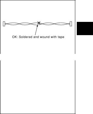
Precautions for Harness Repair |
AKS00BCJ |
CAN SYSTEM
D
E
F
G
H
I
●Solder the repaired parts, and wrap with tape. [Frays of twisted line must be within 110 mm (4.33 in)]
J
LAN
L
|
PKIA0306E |
|
● Do not perform bypass wire connections for the repair parts. |
|
M |
|
||
(The spliced wire will become separated and the characteristics |
|
|
of twisted line will be lost.) |
|
|
PKIA0307E
Revision: 2005 March |
LAN-3 |
2005 X-Trail |
TROUBLE DIAGNOSES WORK FLOW
|
[CAN] |
TROUBLE DIAGNOSES WORK FLOW |
PFP:00004 |
When Displaying CAN Communication System Errors |
AKS00BQF |
WHEN A MALFUNCTION IS DETECTED BY CAN COMMUNICATION SYSTEM |
|
●CAN communication line is open. (CAN H, CAN L, or both)
●CAN communication line is shorted. (Ground, between CAN lines, or other harnesses)
●The areas related to CAN communication of unit is malfunctioning.
WHEN A MALFUNCTION IS DETECTED EXCEPT CAN COMMUNICATION SYSTEM
●Removal and installation of parts: When the units that perform CAN communication or the sensors related to CAN communication are removed and installed, malfunction may be detected (or DTC other than CAN communication may be detected).
●Fuse blown out (removed): CAN communication of the unit may be stopped at such time.
●Low voltage: If the voltage decreases because of battery discharge when IGN is ON, malfunction may be detected by self-diagnosis according to the units.
Revision: 2005 March |
LAN-4 |
2005 X-Trail |
TROUBLE DIAGNOSES WORK FLOW
[CAN]
TROUBLE DIAGNOSIS FLOW CHART
A
B
C
D
E
F
G
H
I
J
LAN
L
PKIA8959E
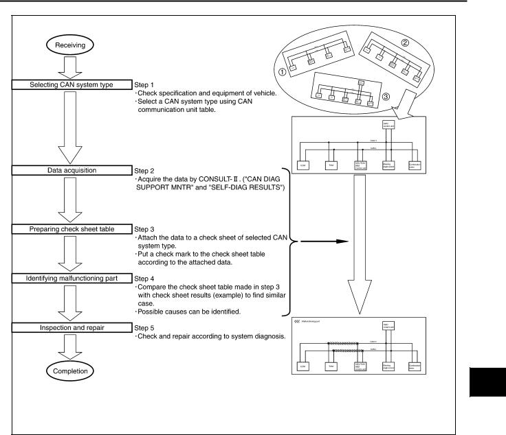
●Step 1: Refer to LAN-6, "SELECTING CAN SYSTEM TYPE (HOW TO USE SPECIFICATION TABLE)" .
● Step 2: Refer to LAN-7, "ACQUISITION OF DATA BY CONSULT-II" . |
M |
●Step 3: Refer to LAN-8, "HOW TO USE CHECK SHEET TABLE" .
●Step 4: Refer to LAN-9, "Example of Filling in Check Sheet When Initial Conditions Are Reproduced" .
●Step 5: Check and repair according to system diagnosis.
Revision: 2005 March |
LAN-5 |
2005 X-Trail |
TROUBLE DIAGNOSES WORK FLOW
[CAN]
Diagnosis Procedure |
AKS00BQG |
SELECTING CAN SYSTEM TYPE (HOW TO USE SPECIFICATION TABLE)
Determine CAN system type from the equipment of the vehicle to select applicable check sheet.
PKIA8960E
Revision: 2005 March |
LAN-6 |
2005 X-Trail |
TROUBLE DIAGNOSES WORK FLOW
[CAN]
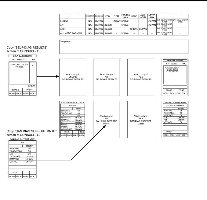
ACQUISITION OF DATA BY CONSULT-II
Attach the data acquired by CONSULT-II on the check sheet determined according to CAN system type. |
A |
||
|
|
|
B |
|
|
|
|
|
|
|
C |
|
|
|
D |
|
|
|
E |
|
|
|
F |
|
|
|
G |
|
|
|
H |
|
|
|
I |
|
|
|
J |
|
|
|
|
|
|
|
LAN |
|
|
|
|
|
|
|
L |
|
PKIA8961E |
|
|
|
|
|
M |
Revision: 2005 March |
LAN-7 |
2005 X-Trail |
TROUBLE DIAGNOSES WORK FLOW
[CAN]
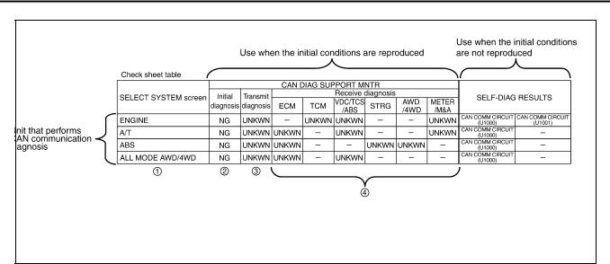
HOW TO USE CHECK SHEET TABLE
PKIA8962E
1.Unit names displayed on CONSULT-II
2.“NG”: Display “NG” when malfunction is detected in the initial diagnosis of the diagnosed unit. Replace the unit if “NG” is displayed.
“–”: Column not used (Initial diagnosis is not performed.)
3.“UNKWN”: Display “UNKWN” when the diagnosed unit does not transmit the data normally. Put a check mark to it if “UNKWN” is displayed on CONSULT-II.
4.“UNKWN”: Display “UNKWN” when the diagnosed unit does not receive the data normally. Put a check mark to it if “UNKWN” is displayed on CONSULT-II.
“–”: Column not used (It is not necessary for CAN communication trouble diagnosis.)
NOTE:
CAN communication diagnosis checks if CAN communication works normally. (Contents of data are not diagnosed.)
●Refer to LAN-9, "Example of Filling in Check Sheet When Initial Conditions Are Reproduced" when the initial conditions are reproduced.
●Refer to LAN-11, "Example of Filling in Check Sheet When Initial Conditions Are Not Reproduced" when the initial conditions are not reproduced.
Revision: 2005 March |
LAN-8 |
2005 X-Trail |
TROUBLE DIAGNOSES WORK FLOW
[CAN]
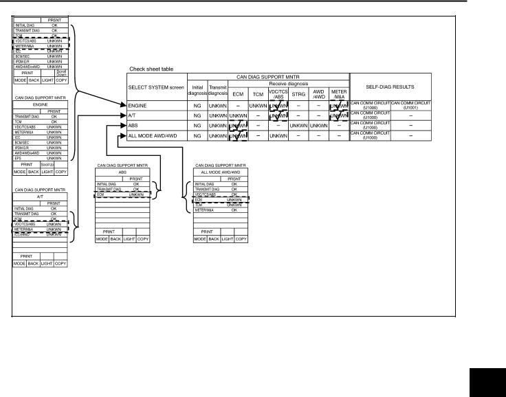
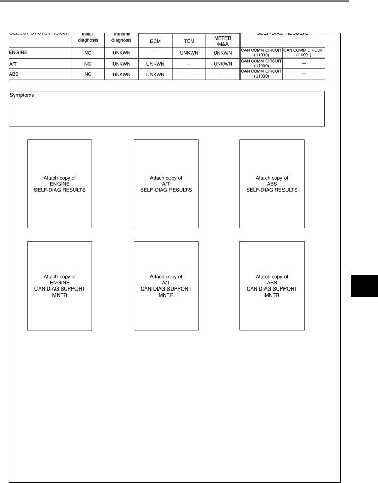
Example of Filling in Check Sheet When Initial Conditions Are Reproduced
A
B
C
D
E
F
G
H
PKIA8963E |
I |
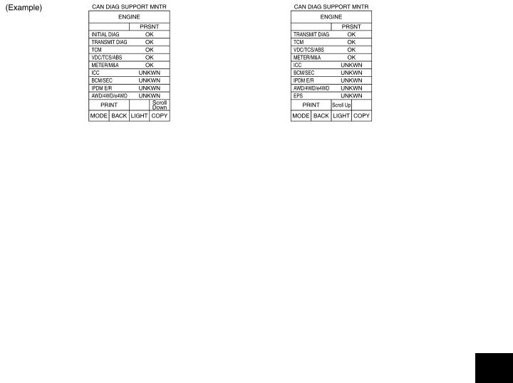
1.Confirm the unit name that “UNKWN” is displayed from the copy of “CAN DIAG SUPPORT MNTR” screen of “ENGINE” attached to the check sheet, and then put a check mark to the check sheet table.
NOTE: J
In “CAN DIAG SUPPORT MNTR” screen, “UNKWN” is displayed on “VDC/TCS/ABS”, “METER/M&A”, “ICC”, “BCM/SEC”, “IPDM E/R”, “AWD/4WD/e4WD” and “EPS”. But put a check mark to “VDC/TCS/ABS”
and “METER/M&A” because “UNKWN” is listed on the column of reception diagnosis of the check sheet
table.
LAN
2. Confirm the unit name that “UNKWN” is displayed on the copy of “CAN DIAG SUPPORT MNTR” screen
of “A/T”, “ABS”, and “ALL MODE AWD/4WD” as well as “ENGINE”. And then, put a check mark to the |
|
check sheet table. |
L |
|
|
NOTE:
●For “A/T”, “UNKWN” is displayed on “VDC/TCS/ABS”, “METER/M&A” and “ICC/e4WD”. Put a check mark to “VDC/TCS/ABS” and “METER/M&A” columns of reception diagnosis on the check sheet table.M (It is not necessary to put a check mark for “ICC/e4WD”, which is not listed on the check sheet table.)
●For “ABS”, “UNKWN” is displayed on “ECM”. Put a check mark to it.
●For “ALL MODE AWD/4WD”, “UNKWN” is displayed on “ECM” and “TCM”. Put a check mark to “ECM” columns of reception diagnosis on the check sheet table. (It is not necessary to put a check mark for “TCM”, which is not listed on the check sheet table.)
Revision: 2005 March |
LAN-9 |
2005 X-Trail |

TROUBLE DIAGNOSES WORK FLOW
[CAN]
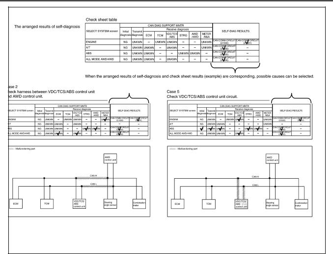
PKIA8964E
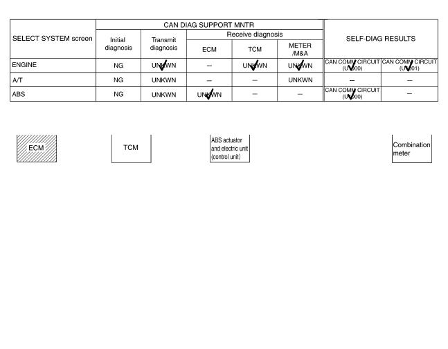
NOTE:
There is a check mark both in “VDC/TCS/ABS” and “METER/M&A” of “A/T” in “The arranged results of CAN diagnosis support monitor” sheet. Also, there is a mark of “–” both in “VDC/TCS/ABS” and “METER/M&A” of “A/T” in the check sheet results (example). Therefore, ignore a check mark both in “VDC/TCS/ABS” and “METER/M&A” of “A/T” in “The arranged results of CAN diagnosis support monitor” sheet.
3.Perform system diagnosis for possible causes identified.
4.Perform diagnosis again after inspection and repair. Make sure that repair is completely performed, and then end the procedure.
Start CAN system trouble diagnosis if this procedure can be confirmed. LAN-16, "CAN Communication Unit"
Revision: 2005 March |
LAN-10 |
2005 X-Trail |
TROUBLE DIAGNOSES WORK FLOW
[CAN]
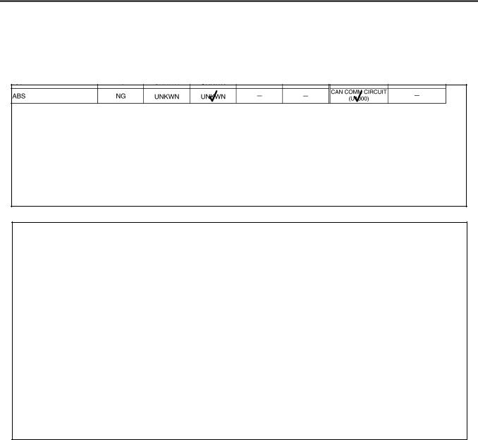
Example of Filling in Check Sheet When Initial Conditions Are Not Reproduced
A
B
C
D
E
F
G
H
PKIA8965E |
I |
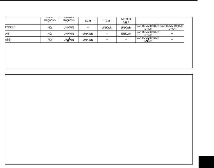
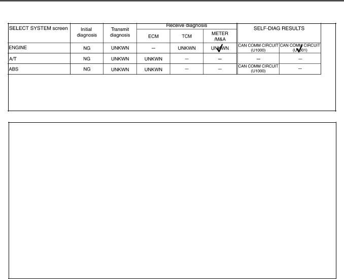
1.See “SELF-DIAG RESULTS” of all units attached to the check sheet. If “CAN COMM CIRCUIT”, “CAN COMM CIRCUIT [U1000]” or “CAN COMM CIRCUIT [U1001]” is displayed, put a check mark to the appli-
cable column of self-diagnostic results of the check sheet table. |
J |
|
NOTE: |
|
|
● |
For “ENGINE”, “CAN COMM CIRCUIT [U1001]” are displayed. Put a check mark to it. |
|
|
||
● |
For “A/T”, “CAN COMM CIRCUIT” is displayed. Put a check mark to it. |
LAN |
●For “ABS”, “CAN COMM CIRCUIT [U1000]” is displayed. Put a check mark to it.
●For “ALL MODE AWD/4WD”, “CAN COMM CIRCUIT [U1000]” is displayed. Put a check mark to it.
L
M
Revision: 2005 March |
LAN-11 |
2005 X-Trail |
TROUBLE DIAGNOSES WORK FLOW
[CAN]
PKIA8966E
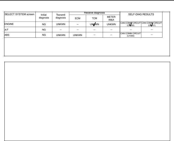
NOTE:
There is a check mark in “CAN COMM CIRCUIT (U1000)” of “A/T” in “The arranged results of self-diagnosis” sheet. Also, there is a mark of “–” in “CAN COMM CIRCUIT (U1000)” of “A/T” in “The arranged results of selfdiagnosis” sheet. Therefore, ignore a check mark in “CAN COMM CIRCUIT (U1000)” of “A/T” in “The arranged results of self-diagnosis” sheet.
2.For the selected possible causes, it is expected that malfunctions have been found in the past.
Revision: 2005 March |
LAN-12 |
2005 X-Trail |
TROUBLE DIAGNOSES WORK FLOW
|
|
[CAN] |
|
|
CAN Diagnostic Support Monitor |
AKS00BQH |
|||
DESCRIPTION OF “CAN DIAG SUPPORT MNTR” SCREEN FOR ECM |
|
|
A |
|
|
|
|
|
B |
|
|
|
|
C |
|
|
|
|
D |
|
|
PKIA8945E |
|
|
“SELECT SYSTEM” |
|
“CAN DIAG SUPPORT |
Description |
Present |
screen |
|
MNTR” screen |
||
|
|
|
||
|
|
|
|
|
|
|
INITIAL DIAG |
Make sure that microcomputer in ECU works normally. |
OK/NG |
|
|
|
|
|
|
|
TRANSMIT DIAG |
Make sure of normal transmission. |
OK/UNKWN |
|
|
|
|
|
|
|
TCM |
Make sure of normal reception from TCM. |
OK/UNKWN |
|
|
|
|
|
|
|
|
VDC/TCS/ABS is not diagnosed. (ABS models) |
UNKWN |
|
|
VDC/TCS/ABS |
|
|
|
|
Make sure of normal reception from VDC/TCS/ABS control unit. |
OK/UNKWN |
|
|
|
|
||
|
|
|
(VDC models) |
|
|
|
|
|
|
ENGINE |
|
|
|
|
|
METER/M&A |
Make sure of normal reception from combination meter. |
OK/UNKWN |
|
|
|
|||
|
|
|
|
|
|
|
ICC |
ICC is not diagnosed. |
UNKWN |
|
|
|
|
|
|
|
BCM/SEC |
BCM/SEC is not diagnosed. |
UNKWN |
|
|
|
|
|
|
|
IPDM E/R |
IPDM E/R is not diagnosed. |
UNKWN |
|
|
|
|
|
|
|
AWD/4WD/e4WD |
AWD/4WD/e4WD is not diagnosed. |
UNKWN |
|
|
|
|
|
|
|
EPS |
EPS is not diagnosed. |
UNKWN |
|
|
|
|
|
Display Results (Present)
●OK: Normal
●NG: Malfunction
●UNKWN: The diagnosed unit does not transmit or receive the applicable data normally.
E
F
G
H
I
J
LAN
L
M
Revision: 2005 March |
LAN-13 |
2005 X-Trail |

TROUBLE DIAGNOSES WORK FLOW
[CAN]
DESCRIPTION OF “CAN DIAG SUPPORT MNTR” SCREEN
FOR TCM
|
|
|
|
PKIA8946E |
|
|
|
|
|
|
|
“SELECT SYSTEM” |
“CAN DIAG SUPPORT |
Description |
Present |
||
screen |
MNTR” screen |
||||
|
|
|
|||
|
|
|
|
||
|
INITIAL DIAG |
Make sure that microcomputer in ECU works normally. |
OK/NG |
||
|
|
|
|
||
|
TRANSMIT DIAG |
Make sure of normal transmission. |
OK/UNKWN |
||
|
|
|
|
||
|
ECM |
Make sure of normal reception from ECM. |
OK/UNKWN |
||
|
|
|
|
||
A/T |
|
VDC/TCS/ABS is not diagnosed. (ABS models) |
UNKWN |
||
VDC/TCS/ABS |
|
|
|
||
|
Make sure of normal reception from VDC/TCS/ABS control unit. |
OK/UNKWN |
|||
|
|
||||
|
|
(VDC models) |
|||
|
|
|
|||
|
|
|
|
||
|
METER/M&A |
Make sure of normal reception from combination meter. |
OK/UNKWN |
||
|
|
|
|
||
|
ICC/e4WD |
ICC/e4WD is not diagnosed. |
UNKWN |
||
|
|
|
|
|
|
Display Results (Present)
●OK: Normal
●NG: Malfunction
●UNKWN: The diagnosed unit does not transmit or receive the applicable data normally.
DESCRIPTION OF “CAN DIAG SUPPORT MNTR” SCREEN
FOR ABS ACTUATOR AND ELECTRIC UNIT (CONTROL
UNIT)
|
|
|
|
|
PKIA8949E |
|
|
|
|
|
|
|
|
“SELECT SYSTEM” |
“CAN DIAG SUPPORT MNTR” |
|
Description |
Present |
|
|
screen |
screen |
|
|
|||
|
|
|
|
|
||
|
|
|
|
|
|
|
|
INITIAL DIAG |
|
Make sure that microcomputer in ECU works normally. |
OK/NG |
|
|
|
|
|
|
|
|
|
ABS |
TRANSMIT DIAG |
|
Make sure of normal transmission. |
OK/UNKWN |
|
|
|
|
|
|
|
|
|
|
ECM |
|
Make sure of normal reception from ECM. |
OK/UNKWN |
|
|
|
|
|
|
|
|
|
Display Results (Present)
●OK: Normal
●NG: Malfunction
●UNKWN: The diagnosed unit does not transmit or receive the applicable data normally.
Revision: 2005 March |
LAN-14 |
2005 X-Trail |

TROUBLE DIAGNOSES WORK FLOW
[CAN]
DESCRIPTION OF “CAN DIAG SUPPORT MNTR” SCREEN
FOR VDC/TCS/ABS CONTROL UNIT
|
|
|
|
|
|
PKIA8947E |
|
|
|
|
|
|
|
“SELECT SYSTEM” |
|
“CAN DIAG SUPPORT MNTR” |
|
Description |
Present |
|
screen |
|
screen |
|
|||
|
|
|
|
|
||
|
|
|
|
|
|
|
|
|
INITIAL DIAG |
|
Make sure that microcomputer in ECU works normally. |
OK/UNKWN |
|
|
|
|
|
|
|
|
|
|
TRANSMIT DIAG |
|
Make sure of normal transmission. |
OK/UNKWN |
|
|
|
|
|
|
|
|
|
|
ECM |
|
Make sure of normal reception from ECM. |
OK/UNKWN |
|
ABS |
|
|
|
|
|
|
|
TCM |
|
Make sure of normal reception from TCM. |
OK/UNKWN |
||
|
|
|
||||
|
|
|
(Not available for CAN system diagnosis.) |
|||
|
|
|
|
|
||
|
|
|
|
|
|
|
|
|
STRG |
|
Make sure of normal reception from Steering angle sensor. |
OK/UNKWN |
|
|
|
|
|
|
|
|
|
|
AWD/4WD |
|
Make sure of normal reception from AWD control unit. |
OK/UNKWN |
|
|
|
|
|
|
|
|
Display Results (Present)
●OK: Normal
●NG: Malfunction
●UNKWN: The diagnosed unit does not transmit or receive the applicable data normally.
A
B
C
D
E
F
G
H
DESCRIPTION OF “CAN DIAG SUPPORT MNTR” SCREEN
FOR AWD CONTROL UNIT
|
|
|
|
PKIA8948E |
|
|
|
|
|
|
|
“SELECT SYSTEM” |
“CAN DIAG SUPPORT |
Description |
Present |
||
screen |
MNTR” screen |
||||
|
|
|
|||
|
|
|
|
||
|
INITIAL DIAG |
Make sure that microcomputer in ECU works normally. |
OK/NG |
||
|
|
|
|
||
|
TRANSMIT DIAG |
Make sure of normal transmission. |
OK/UNKWN |
||
|
|
|
|
||
|
|
Make sure of normal reception from ABS actuator and electric |
OK/UNKWN |
||
|
VDC/TCS/ABS |
unit (control unit). |
|||
|
|
||||
ALL MODE AWD/ |
|
|
|
||
|
|
|
|
||
|
Make sure of normal reception from VDC/TCS/ABS control unit. |
OK/UNKWN |
|||
4WD |
|
||||
|
|
|
|
||
|
ECM |
Make sure of normal reception from ECM. |
OK/UNKWN |
||
|
|
|
|
||
|
TCM |
TCM is not diagnosed. |
UNKWN |
||
|
|
|
|
||
|
METER/M&A |
Make sure of normal reception from combination meter. |
OK/UNKWN |
||
|
(Not available for CAN system diagnosis.) |
||||
|
|
|
|||
|
|
|
|
|
|
Display Results (Present)
●OK: Normal
●NG: Malfunction
●UNKWN: The diagnosed unit does not transmit or receive the applicable data normally.
I
J
LAN
L
M
Revision: 2005 March |
LAN-15 |
2005 X-Trail |
|
CAN COMMUNICATION |
|
[CAN] |
|
|
CAN COMMUNICATION |
PFP:23710 |
System Description |
AKS00BCK |
CAN (Controller Area Network) is a serial communication line for real time application. It is an on-vehicle multiplex communication line with high data communication speed and excellent error detection ability. Many electronic control units are equipped onto a vehicle, and each control unit shares information and links with other control units during operation (not independent). In CAN communication, control units are connected with 2 communication lines (CAN H line, CAN L line) allowing a high rate of information transmission with less wiring. Each control unit transmits/receives data but selectively reads required data only.
CAN Communication Unit |
|
|
|
|
|
|
AKS00BCL |
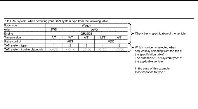
Go to CAN system, when selecting your CAN system type from the following table. |
|
|
|
||||
|
|
|
|
|
|
|
|
Body type |
|
|
Wagon |
|
|
|
|
|
|
|
|
|
|
|
|
Axle |
2WD |
|
AWD |
|
|
|
|
|
|
|
|
|
|
|
|
Engine |
|
|
QR25DE |
|
|
|
|
|
|
|
|
|
|
|
|
Transmission |
A/T |
M/T |
A/T |
|
M/T |
|
A/T |
|
|
|
|
|
|
|
|
Brake control |
|
ABS |
|
|
|
VDC |
|
|
|
|
|
|
|
|
|
CAN system type |
1 |
2 |
3 |
|
4 |
|
5 |
|
|
|
|
|
|
|
|
CAN system trouble diagnosis |
LAN-22 |
LAN-39 |
LAN-55 |
|
LAN-76 |
|
LAN-93 |
|
|
|
|
|
|
|
|
PKIA9660E
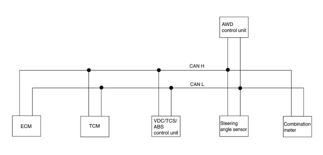
TYPE 1
System Diagram
SKIB0001E
Revision: 2005 March |
LAN-16 |
2005 X-Trail |
CAN COMMUNICATION
|
|
|
|
[CAN] |
Input/Output Signal Chart |
|
|
|
|
|
|
|
|
T: Transmit R: Receive |
|
|
|
|
|
|
|
|
ABS actuator and |
|
Signals |
ECM |
TCM |
electric unit |
Combination meter |
|
|
|
(control unit) |
|
|
|
|
|
|
Stop lamp switch signal |
|
R |
|
T |
|
|
|
|
|
A/T self-diagnosis signal |
R |
T |
|
|
|
|
|
|
|
A/T position indicator lamp signal |
|
T |
|
R |
|
|
|
|
|
Overdrive control switch signal |
|
R |
|
T |
|
|
|
|
|
O/D OFF indicator signal |
|
T |
|
R |
|
|
|
|
|
Closed throttle position signal |
T |
R |
|
|
|
|
|
|
|
Wide open throttle position signal |
T |
R |
|
|
|
|
|
|
|
Engine speed signal |
T |
|
|
R |
|
|
|
|
|
Engine coolant temperature signal |
T |
|
|
R |
|
|
|
|
|
Output shaft revolution signal |
R |
T |
|
|
|
|
|
|
|
A/C compressor feedback signal |
T |
|
|
R |
|
|
|
|
|
Vehicle speed signal |
|
|
T |
R |
|
|
|
|
|
R |
|
|
T |
|
|
|
|
||
|
|
|
|
|
ABS warning lamp signal |
|
|
T |
R |
|
|
|
|
|
Fuel level sensor signal |
R |
|
|
T |
|
|
|
|
|
Malfunction indicator lamp signal |
T |
|
|
R |
|
|
|
|
|
ASCD SET lamp signal |
T |
|
|
R |
|
|
|
|
|
ASCD CRUISE lamp signal |
T |
|
|
R |
|
|
|
|
|
Engine A/T integrated control signal |
T |
R |
|
|
|
|
|
|
|
R |
T |
|
|
|
|
|
|
||
|
|
|
|
|
Snow mode switch signal |
R |
|
|
T |
|
|
|
|
|
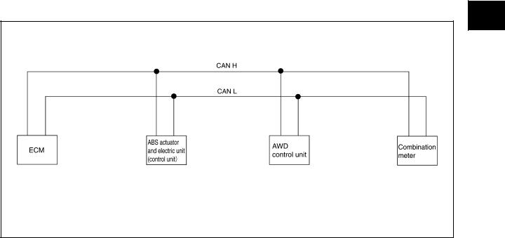
TYPE 2 |
|
|
|
|
System Diagram |
|
|
|
|
PKIA8837E
A
B
C
D
E
F
G
H
I
J
LAN
L
M
Revision: 2005 March |
LAN-17 |
2005 X-Trail |
CAN COMMUNICATION
|
|
|
|
|
[CAN] |
Input/Output Signal Chart |
|
|
|
|
|
|
|
|
|
T: Transmit R: Receive |
|
|
|
|
|
|
|
|
|
ABS actuator and |
|
|
|
Signals |
ECM |
electric unit (control |
AWD control unit |
|
Combination meter |
|
|
unit) |
|
|
|
|
|
|
|
|
|
Stop lamp switch signal |
|
T |
R |
|
|
|
|
|
|
|
|
Engine speed signal |
T |
|
R |
|
R |
|
|
|
|
|
|
Engine coolant temperature signal |
T |
|
|
|
R |
|
|
|
|
|
|
Accelerator pedal position signal |
T |
|
R |
|
|
|
|
|
|
|
|
A/C compressor feedback signal |
T |
|
|
|
R |
|
|
|
|
|
|
Vehicle speed signal |
|
T |
R |
|
R |
|
|
|
|
|
|
R |
|
|
|
T |
|
|
|
|
|
||
|
|
|
|
|
|
ABS warning lamp signal |
|
T |
|
|
R |
|
|
|
|
|
|
AWD warning lamp signal |
|
|
T |
|
R |
|
|
|
|
|
|
AWD mode indicator lamp signal |
|
|
T |
|
R |
|
|
|
|
|
|
Parking brake switch signal |
|
|
R |
|
T |
|
|
|
|
|
|
Fuel level sensor signal |
R |
|
|
|
T |
|
|
|
|
|
|
Malfunction indicator lamp signal |
T |
|
|
|
R |
|
|
|
|
|
|
ASCD SET lamp signal |
T |
|
|
|
R |
|
|
|
|
|
|
ASCD CRUISE lamp signal |
T |
|
|
|
R |
|
|
|
|
|
|
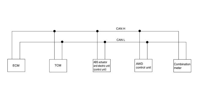
TYPE 3 |
|
|
|
|
|
System Diagram |
|
|
|
|
|
|
|
|
|
|
|
PKIA8843E |
|
Input/Output Signal Chart |
|
|
|
|
|
|
|
|
|
|
|
|
T: Transmit R: Receive |
||
|
|
|
|
|
|
|
|
|
|
|
|
ABS actuator |
AWD control |
Combination |
|
|
Signals |
ECM |
TCM |
and electric unit |
|||
|
unit |
meter |
|||||
|
|
|
|
(control unit) |
|||
|
|
|
|
|
|
|
|
|
|
|
|
|
|
|
|
Stop lamp switch signal |
|
R |
|
|
T |
||
|
|
|
|
|
|
||
|
|
T |
R |
|
|
||
|
|
|
|
|
|
||
|
|
|
|
|
|
|
|
A/T self-diagnosis signal |
R |
T |
|
|
|
|
|
|
|
|
|
|
|
||
A/T position indicator lamp signal |
|
T |
|
|
R |
||
|
|
|
|
|
|
||
Overdrive control switch signal |
|
R |
|
|
T |
||
|
|
|
|
|
|
|
|
Revision: 2005 March |
LAN-18 |
2005 X-Trail |
CAN COMMUNICATION
|
|
|
|
|
[CAN] |
|
|
|
|
|
|
|
|
|
|
|
ABS actuator |
AWD control |
Combination |
|
Signals |
ECM |
TCM |
and electric unit |
|||
unit |
meter |
|||||
|
|
|
(control unit) |
|||
|
|
|
|
|
||
|
|
|
|
|
|
|
O/D OFF indicator signal |
|
T |
|
|
R |
|
|
|
|
|
|
|
|
Closed throttle position signal |
T |
R |
|
|
|
|
|
|
|
|
|
|
|
Wide open throttle position signal |
T |
R |
|
|
|
|
|
|
|
|
|
|
|
Engine speed signal |
T |
|
|
R |
R |
|
|
|
|
|
|
|
|
Engine coolant temperature signal |
T |
|
|
|
R |
|
|
|
|
|
|
|
|
Output shaft revolution signal |
R |
T |
|
|
|
|
|
|
|
|
|
|
|
A/C compressor feedback signal |
T |
|
|
|
R |
|
|
|
|
|
|
|
|
Vehicle speed signal |
|
|
T |
R |
R |
|
|
|
|
|
|
||
R |
|
|
|
T |
||
|
|
|
|
|||
|
|
|
|
|
|
|
ABS warning lamp signal |
|
|
T |
|
R |
|
|
|
|
|
|
|
|
AWD warning lamp signal |
|
|
|
T |
R |
|
|
|
|
|
|
|
|
AWD mode indicator lamp signal |
|
|
|
T |
R |
|
|
|
|
|
|
|
|
Parking brake switch signal |
|
|
|
R |
T |
|
|
|
|
|
|
|
|
Fuel level sensor signal |
R |
|
|
|
T |
|
|
|
|
|
|
|
|
Malfunction indicator lamp signal |
T |
|
|
|
R |
|
|
|
|
|
|
|
|
ASCD SET lamp signal |
T |
|
|
|
R |
|
|
|
|
|
|
|
|
ASCD CRUISE lamp signal |
T |
|
|
|
R |
|
|
|
|
|
|
|
|
Engine A/T integrated control signal |
T |
R |
|
|
|
|
|
|
|
|
|
||
R |
T |
|
|
|
||
|
|
|
|
|||
|
|
|
|
|
|
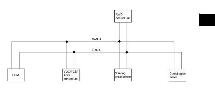
TYPE 4
System Diagram
|
|
|
|
|
|
PKIA8851E |
|
Input/Output Signal Chart |
|
|
|
|
|
|
|
|
|
|
|
|
T: Transmit R: Receive |
||
|
|
|
|
|
|
|
|
|
Signals |
ECM |
VDC/TCS/ABS |
Steering angle |
AWD control |
Combination |
|
|
control unit |
sensor |
unit |
meter |
|||
|
|
|
|||||
|
|
|
|
|
|
|
|
Stop lamp switch signal |
|
T |
|
R |
|
|
|
|
|
|
|
|
|
||
Engine speed signal |
T |
R |
|
R |
R |
||
|
|
|
|
|
|
||
Engine coolant temperature signal |
T |
|
|
|
R |
||
|
|
|
|
|
|
|
|
A
B
C
D
E
F
G
H
I
J
LAN
L
M
Revision: 2005 March |
LAN-19 |
2005 X-Trail |
CAN COMMUNICATION
|
|
|
|
|
|
[CAN] |
||
|
|
|
|
|
|
|
|
|
Signals |
ECM |
VDC/TCS/ABS |
Steering angle |
AWD control |
Combination |
|||
control unit |
sensor |
unit |
meter |
|||||
|
|
|
||||||
|
|
|
|
|
|
|
|
|
Accelerator pedal position signal |
T |
R |
|
R |
|
|
||
|
|
|
|
|
|
|
|
|
A/C compressor feedback signal |
T |
|
|
|
R |
|||
|
|
|
|
|
|
|
|
|
Vehicle speed signal |
|
|
T |
|
R |
R |
||
|
|
|
|
|
|
|
||
|
R |
|
|
|
T |
|||
|
|
|
|
|
||||
|
|
|
|
|
|
|
||
ABS warning lamp signal |
|
T |
|
|
R |
|||
|
|
|
|
|
|
|
||
Brake warning lamp signal |
|
T |
|
|
R |
|||
|
|
|
|
|
|
|
||
SLIP indicator lamp signal |
|
T |
|
|
R |
|||
|
|
|
|
|
|
|
||
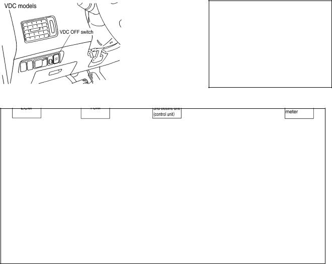
VDC OFF indicator lamp signal |
|
T |
|
|
R |
|||
|
|
|
|
|
|
|
||
AWD warning lamp signal |
|
|
|
T |
R |
|||
|
|
|
|
|
|
|
||
AWD mode indicator lamp signal |
|
|
|
T |
R |
|||
|
|
|
|
|
|
|
||
Parking brake switch signal |
|
|
|
R |
T |
|||
|
|
|
|
|
|
|
||
Fuel level sensor signal |
R |
|
|
|
T |
|||
|
|
|
|
|
|
|
||
Malfunction indicator lamp signal |
T |
|
|
|
R |
|||
|
|
|
|
|
|
|
||
ASCD SET lamp signal |
T |
|
|
|
R |
|||
|
|
|
|
|
|
|
||
ASCD CRUISE lamp signal |
T |
|
|
|
R |
|||
|
|
|
|
|
|
|
||
Steering angle sensor signal |
|
R |
T |
|
|
|
||
|
|
|
|
|
|
|
|
|
TYPE 5
System Diagram
|
|
|
|
|
|
|
PKIA8858E |
|
Input/Output Signal Chart |
|
|
|
|
|
|
|
|
|
|
|
|
|
|
T: Transmit R: Receive |
||
|
|
|
|
|
|
|
|
|
|
|
|
|
VDC/TCS/ |
Steering |
AWD control |
Combination |
|
|
Signals |
ECM |
TCM |
ABS control |
||||
|
angle sensor |
unit |
meter |
|||||
|
|
|
|
unit |
||||
|
|
|
|
|
|
|
|
|
|
|
|
|
|
|
|
|
|
Stop lamp switch signal |
|
R |
|
|
|
T |
||
|
|
|
|
|
|
|
||
|
|
T |
|
R |
|
|
||
|
|
|
|
|
|
|
||
|
|
|
|
|
|
|
||
A/T position indicator lamp signal |
|
T |
R |
|
|
R |
||
|
|
|
|
|
|
|
||
O/D OFF indicator signal |
|
T |
|
|
|
R |
||
|
|
|
|
|
|
|
||
Overdrive control switch signal |
|
R |
|
|
|
T |
||
|
|
|
|
|
|
|
|
|
Closed throttle position signal |
T |
R |
|
|
|
|
|
|
|
|
|
|
|
|
|
|
|
Revision: 2005 March |
LAN-20 |
2005 X-Trail |
CAN COMMUNICATION
|
|
|
|
|
|
[CAN] |
|
|
|
|
|
|
|
|
|
|
|
|
VDC/TCS/ |
Steering |
AWD control |
Combination |
|
Signals |
ECM |
TCM |
ABS control |
||||
angle sensor |
unit |
meter |
|||||
|
|
|
unit |
||||
|
|
|
|
|
|
||
|
|
|
|
|
|
|
|
Wide open throttle position signal |
T |
R |
|
|
|
|
|
|
|
|
|
|
|
|
|
Engine speed signal |
T |
|
R |
|
R |
R |
|
|
|
|
|
|
|
|
|
Engine coolant temperature signal |
T |
|
|
|
|
R |
|
|
|
|
|
|
|
|
|
Accelerator pedal position signal |
T |
|
R |
|
R |
|
|
|
|
|
|
|
|
|
|
Output shaft revolution signal |
R |
T |
|
|
|
|
|
|
|
|
|
|
|
|
|
A/C compressor feedback signal |
T |
|
|
|
|
R |
|
|
|
|
|
|
|
|
|
Vehicle speed signal |
|
|
T |
|
R |
R |
|
|
|
|
|
|
|
||
R |
|
|
|
|
T |
||
|
|
|
|
|
|||
|
|
|
|
|
|
|
|
ABS warning lamp signal |
|
|
T |
|
|
R |
|
|
|
|
|
|
|
|
|
Brake warning lamp signal |
|
|
T |
|
|
R |
|
|
|
|
|
|
|
|
|
SLIP indicator lamp signal |
|
|
T |
|
|
R |
|
|
|
|
|
|
|
|
|
VDC OFF indicator lamp signal |
|
|
T |
|
|
R |
|
|
|
|
|
|
|
|
|
AWD warning lamp signal |
|
|
|
|
T |
R |
|
|
|
|
|
|
|
|
|
AWD mode indicator lamp signal |
|
|
|
|
T |
R |
|
|
|
|
|
|
|
|
|
Parking brake switch signal |
|
|
|
|
R |
T |
|
|
|
|
|
|
|
|
|
Fuel level sensor signal |
R |
|
|
|
|
T |
|
|
|
|
|
|
|
|
|
Malfunction indicator lamp signal |
T |
|
|
|
|
R |
|
|
|
|
|
|
|
|
|
ASCD SET lamp signal |
T |
|
|
|
|
R |
|
|
|
|
|
|
|
|
|
ASCD CRUISE lamp signal |
T |
|
|
|
|
R |
|
|
|
|
|
|
|
|
|
Steering angle sensor signal |
|
|
R |
T |
|
|
|
|
|
|
|
|
|
|
|
Engine and A/T integrated control |
T |
R |
|
|
|
|
|
|
|
|
|
|
|
||
signal |
|
|
|
|
|
|
|
R |
T |
|
|
|
|
||
|
|
|
|
|
|||
|
|
|
|
|
|
|
|
A/T self-diagnosis signal |
R |
T |
|
|
|
|
|
|
|
|
|
|
|
|
A
B
C
D
E
F
G
H
I
J
LAN
L
M
Revision: 2005 March |
LAN-21 |
2005 X-Trail |
CAN SYSTEM (TYPE 1)
|
[CAN] |
CAN SYSTEM (TYPE 1) |
PFP:23710 |
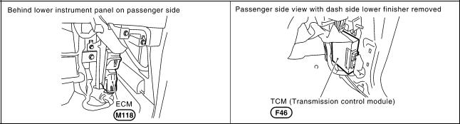
Component Parts and Harness Connector Location |
AKS00BK2 |
SKIB0329E
Revision: 2005 March |
LAN-22 |
2005 X-Trail |
CAN SYSTEM (TYPE 1)
[CAN]
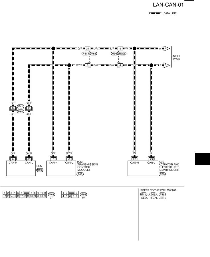
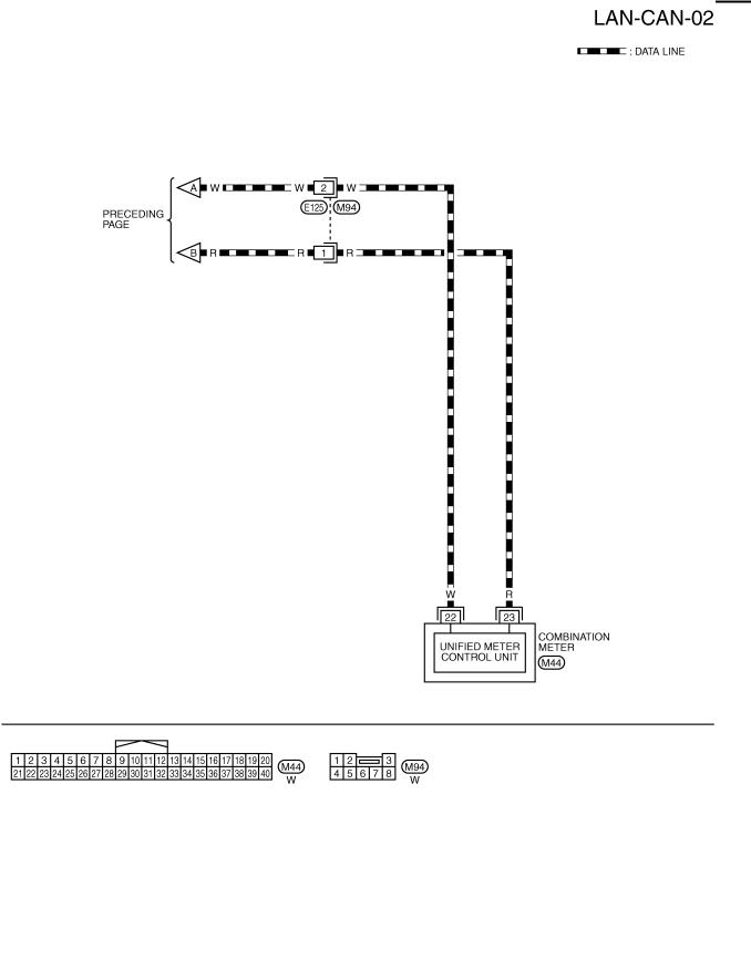
Wiring Diagram — CAN — |
AKS00BK3 |
A
B
C
D
E
F
G
H
I
J
LAN
L
M
TKWB0214E
Revision: 2005 March |
LAN-23 |
2005 X-Trail |
CAN SYSTEM (TYPE 1)
[CAN]
TKWB0215E
Revision: 2005 March |
LAN-24 |
2005 X-Trail |
CAN SYSTEM (TYPE 1)
[CAN]
Check Sheet |
AKS00BK4 |
A
NOTE:
If a check mark is put on “NG” on “INITIAL DIAG (Initial diagnosis)”, replace the control unit.
B
C
D
E
F
G
H
I
J
LAN
L
M
PKIA8754E
Revision: 2005 March |
LAN-25 |
2005 X-Trail |
CAN SYSTEM (TYPE 1)
[CAN]
CHECK SHEET RESULTS (EXAMPLE)
NOTE:
If a check mark is put on “NG” on “INITIAL DIAG (Initial diagnosis)”, replace the control unit.
Case 1
Check harness between TCM and ABS actuator and electric unit (control unit). Refer to LAN-31, "Between TCM and ABS Actuator and Electric Unit (Control Unit) Circuit Inspection" .
PKIA8755E
PKIA7564E
Revision: 2005 March |
LAN-26 |
2005 X-Trail |
CAN SYSTEM (TYPE 1)
|
|
[CAN] |
|||
Case 2 |
|
|
|
|
|
Check ECM circuit. Refer to LAN-32, "ECM Circuit Inspection" . |
|
|
|
A |
|
|
|
|
|
|
B |
|
|
|
|
|
|
|
|
|
|
|
C |
|
|
|
|
|
D |
|
|
PKIA8756E |
|
||
|
|
|
|
|
E |
|
|
|
|
|
|
|
|
|
|
|
F |
|
|
|
|
|
G |
|
|
|
|
|
H |
|
|
|
|
|
I |
|
|
|
|
|
J |
|
|
PKIA7565E |
|
|
|
|
|
|
|
||
|
|
|
|
|
LAN |
|
|
|
|
|
|
|
|
|
|
|
L |
|
|
|
|
|
M |
Revision: 2005 March |
LAN-27 |
2005 X-Trail |
CAN SYSTEM (TYPE 1)
[CAN]
Case 3
Check TCM circuit. Refer to LAN-33, "TCM Circuit Inspection" .
PKIA8757E
PKIA7566E
Revision: 2005 March |
LAN-28 |
2005 X-Trail |
CAN SYSTEM (TYPE 1)
[CAN]
Case 4
Check ABS actuator and electric unit (control unit) circuit. Refer to LAN-33, "ABS Actuator and Electric Unit A (Control Unit) Circuit Inspection" .
B
C
D
PKIA8758E
E
F
G
H
I
J
PKIA7567E LAN
L
M
Revision: 2005 March |
LAN-29 |
2005 X-Trail |
CAN SYSTEM (TYPE 1)
[CAN]
Case 5
Check combination meter circuit. Refer to LAN-34, "Combination Meter Circuit Inspection" .
PKIA8759E
PKIA7568E
Revision: 2005 March |
LAN-30 |
2005 X-Trail |
Loading...