


XTrail T30 2005
Table of contents
 Loading...
RAX-1
REAR AXLE
D DRIVELINE/AXLE
CONTENTS
C
E
F
G
H
I
J
K
L
M
SECTION RAX
A
B
RAX
Revision: 2005 March 2005 X-Trail
REAR AXLE
2WD
PREPARATION .............................. .................... ......... 2
Special Service Tools [SST] ..................................... 2
Commercial Service Tools ........................................ 3
NOISE, VIBRATION AND HARSHNESS (NVH)
TROUBLESHOOTING .......................... ...................... 4
NVH Troubleshooting Chart ..................................... 4
WHEEL HUB .............................................................. 5
On-Vehicle Inspection and Service .......................... 5
WHEEL BEARING INSPECTION ......................... 5
Removal and Installation .......................................... 5
COMPONENT .................... ................................... 5
REMOVAL ............................................................. 5
INSPECTION AFTER REMOVAL ......................... 6
INSTALLATION ..................................................... 6
Disassembly and Assembly ..................................... 7
DISASSEMBLY ..................................................... 7
INSPECTION AFTER DISASSEMBLY ................. 8
ASSEMBLY ........................................................... 8
INSPECTION AFTER ASSEMBLY ....................... 9
SERVICE DATA AND SPECIFICATIONS (SDS) ...... 10
Wheel Bearing ........................................................ 10
AWD
PRECAUTIONS .........................................................11
Caution ..................... ...............................................11
PREPARATION .............................. .................... ....... 12
Special Service Tools [SST] ................................... 12
Commercial Service Tools ...................................... 13
NOISE, VIBRATION AND HARSHNESS (NVH)
TROUBLESHOOTING ...................... ........................14
NVH Troubleshooting Chart ................................... 14
WHEEL HUB ............................................................. 15
On-Vehicle Inspection and Service ......................... 15
WHEEL BEARING INSPECTION .......................15
Removal and Installation ........................................15
COMPONENT .....................................................15
REMOVAL ...........................................................15
INSPECTION AFTER REMOVAL .......................17
INSTALLATION ................................................... 17
Disassembly and Assembly .................................... 17
DISASSEMBLY ...................................................17
INSPECTION AFTER DISASSEMBLY ................ 17
ASSEMBLY .........................................................18
INSPECTION AFTER ASSEMBLY ......................19
REAR DRIVE SHAFT ............................................... 20
Removal and Installation ........................................20
COMPONENT .....................................................20
REMOVAL ...........................................................20
INSPECTION AFTER REMOVAL .......................20
INSTALLATION ................................................... 20
Disassembly and Assembly .................................... 21
COMPONENT .....................................................21
DISASSEMBLY ...................................................21
INSPECTION AFTER DISASSEMBLY ................ 23
ASSEMBLY .........................................................23
SERVICE DATA AND SPECIFICATIONS (SDS) ......26
Wheel Bearing ........................................................26
Drive Shaft ................................ ...... ....... ...... ........... 26
RAX-2
[2WD]
PREPARATION
Revision: 2005 March 2005 X-Trail
[2WD]
PREPARATION PFP:00002
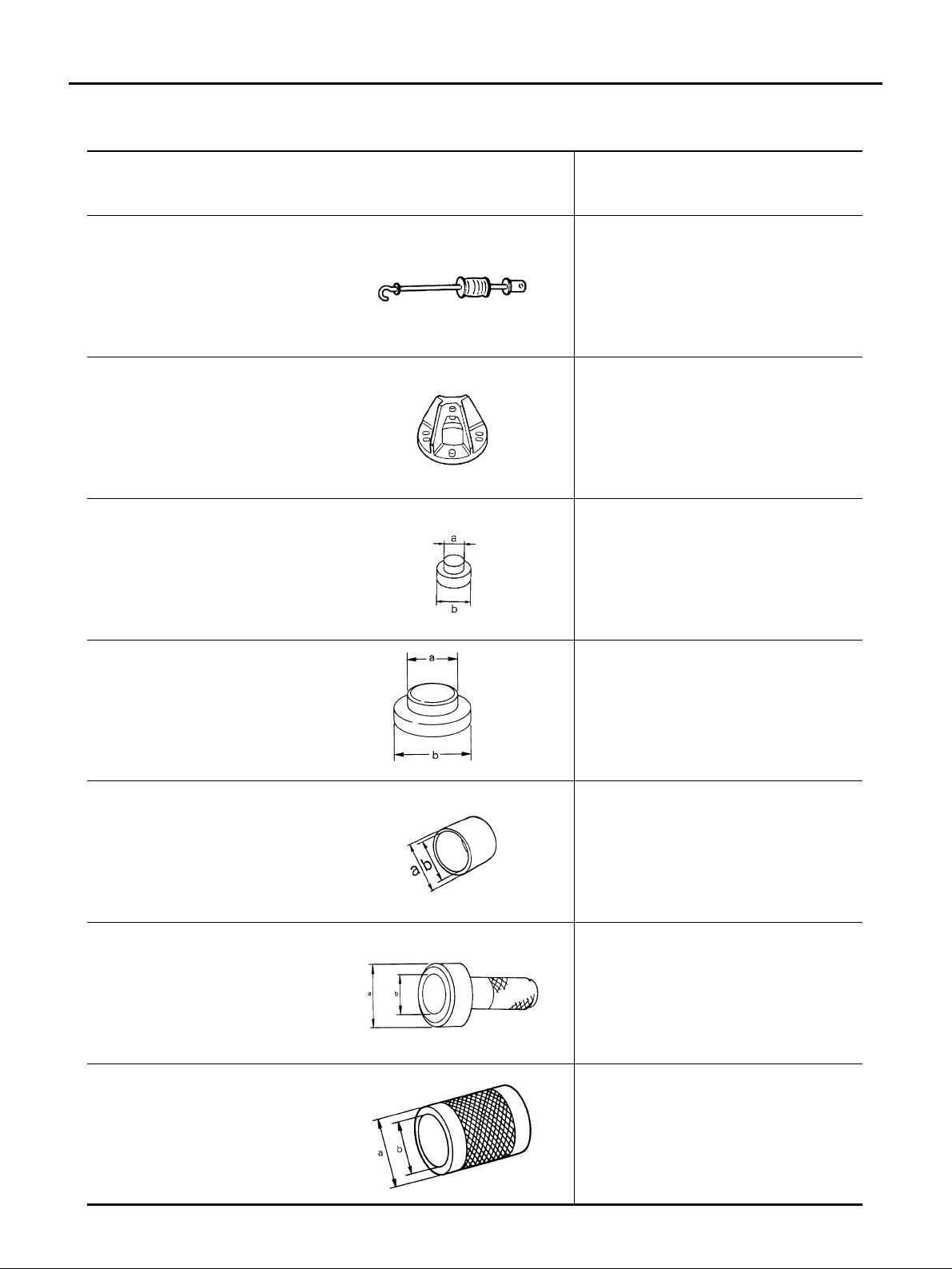
Special Service Tools [SST] ADS0015E
Tool number
(Kent-Moore No.)
Tool name
Description
ST36230000
(J-25840-A)
Slidin g hammer
Removing wheel hub
KV40104100
(–)
Attachment
Removing wheel hub
ST33061000
(J-8107-2)
Drift
a: 28.5 mm (1.122 in) dia.
b: 38.0 mm (1.496 in) dia.
Removing wheel bearing outer side inner
race
ST15242000
(–)
Drift
a: 47.7 mm (1.878 in) dia.
b: 69 mm (2.72 in) dia.
Removing wheel bearing
KV40105310
(–)
Drift
a: 75 mm (2.95 in) dia.
b: 62 mm (2.44 in) dia.
● Removing wheel bearing
● Installing wheel hub
ST30720000
(J-25405)
Drift
a: 77 mm (3.03 in) dia.
b: 55.5 mm (2.185 in) dia.
Installing wheel bearing
ST33200000
(J-26082)
Drift
a: 60 mm (2.36 in) dia.
b: 44.5 mm (1.752 in) dia.
Installing wheel hub
ZZA0803D
ZZA0804D
ZZA0969D
ZZA0881D
ZZA1003D
ZZA0811D
ZZA1002D
PREPARATION
RAX-3
[2WD]
C
E
F
G
H
I
J
K
L
M
A
B
RAX
Revision: 2005 March 2005 X-Trail
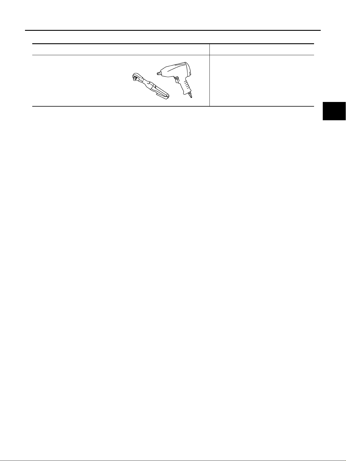
Commercial Service Tools ADS0016X
Tool name Description
Power tool
● Removing wheel nuts
● Removing torque member fixing bolts
PBIC0190E
RAX-4
[2WD]
NOISE, VIBRATION AND HARSHNESS (NVH) TROUBLESHOOTING
Revision: 2005 March 2005 X-Trail
NOISE, VIBRATION AND HARSHNESS (NVH) TROUBLESHOOTING PFP:00003
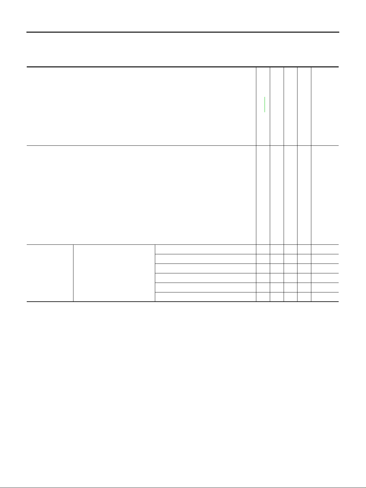
NVH Troubleshooting Chart ADS0015F
Use chart below to help you find the cause of the symptom. If necessary, repair or replace these parts.
×: Applicable
Reference page
RAX-5
—
NVH in RAX and RSU sections
NVH in WT section
NVH in WT section
Possible cause and Suspected parts
Improper installation, looseness
Parts interference
REAR AXLE AND REAR SUSPENSION
TIRES
ROAD WHEELS
BRAKES
Symptom Rear axle
Noise ЧЧЧЧЧ
×
Shake ЧЧЧЧЧЧ
Vibration ××××
Shimmy ЧЧЧЧЧЧ
Judder × ××××
Poor quality ride or handling ЧЧЧЧЧ

WHEEL HUB
RAX-5
[2WD]
C
E
F
G
H
I
J
K
L
M
A
B
RAX
Revision: 2005 March 2005 X-Trail
WHEEL HUB PFP:43202
On-Vehicle Inspection and Service ADS0015G
Make sure that the mounting conditions (looseness, backlash) of each of the components and the component
conditions (wear, damage) are normal.
WHEEL BEARING INSPECTION
● Move wheel hub i n the axial direction by ha nd. Make sure there is no loos eness of wheel bearing.
● Rotate wheel hub and make su re that is no unusual no ise or other irregula r conditions. If there is any of
irregular conditions, replace wheel bearing.
Removal and Installation ADS0015H
COMPONENT
REMOVAL
1. Remove tires from vehicle with a power tool.
2. Remove whee l se ns or from axle ho us in g. R efe r to BRC-36, "
WHEEL SENSORS" .
CAUTION:
Do not pull on wheel sensor harness.
3. Remove torque member fix ing bolts with a p ower tool. Hang torque member in a place whe re it will not
interfere with work. Refer to BR-25, "
FRONT DISC BRAKE" .
NOTE:
Avoid depressing brake pedal while brake caliper is removed.
Axial end play : 0.05 mm (0.002 in) or less
1. Sensor rotor 2. Snap ring 3. Wheel bearing
4. Axle housing 5. Back plate 6. Anchor block
7. Wheel hub
SDIA2494E

RAX-6
[2WD]
WHEEL HUB
Revision: 2005 March 2005 X-Trail
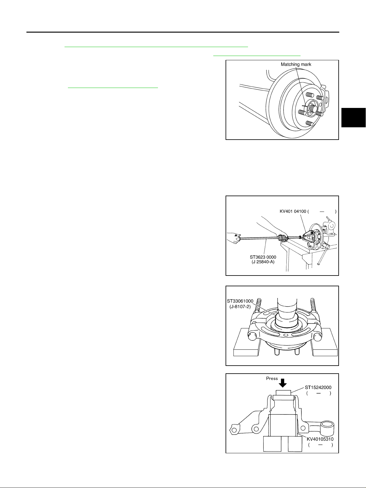
4. Put matching mark on disc rotor and wheel hub, then remove
disc rotor.
5. Remove parking brak e sh oe an d parki ng bra ke c able from bac k
plate. Refer to BR-31, "
REAR DISC BRAKE" .
6. Remove fixing bolts and nuts, and then remove axle housing
from strut assembly. Refer to RSU-7, "
Component" .
7. Remove fixin g nut and bolt of axle housin g side of radius rod,
and then remove radius rod from axle housing. Refer to RSU-7,
"Component" .
8. Remove fixing bolt, washer and nut of axle housing side of front
and rear parallel links, and then remove front and rear para llel
links from axle housing.
9. Remove axle housing from vehicle.
INSPECTION AFTER REMOVAL
Check the components for deformation, cracks and other damage. Replac e if the re.
INSTALLATION
● Install in the reverse order of the removal. For tightening torque, refer to RAX-5, "COMPONENT" .
NOTE:
Do not reuse non-reusable parts.
● Perform the final tighte ning of e ach of parts, u nder unla den cond ition , whic h w ere r emov ed wh en re mov -
ing wheel hub an d axle housin g. Check the whee l align ment. R efer to RSU-5 , "
Wheel Alignment Inspec-
tion" .
SDIA2512E
SDIA2513E
SDIA2514E
SDIA2515E
WHEEL HUB
RAX-7
[2WD]
C
E
F
G
H
I
J
K
L
M
A
B
RAX
Revision: 2005 March 2005 X-Trail
● Adjust neutral position of steering angle sensor after the checking wheel alignment for model with VDC.
Refer to BRC-43, "
Adjustment of Steering Angle Sensor Neutral Position" .
● Check wheel sensor harness for proper connection. Refer to BRC-36, "WHEEL SENSORS" .
● Assembly disc rotor and wheel hub by aligning each matching
mark as shown in the figure when installing disc rotor.
NOTE:
Refer to BR-31, "
REAR DISC BRAKE" for assembly when
removing disc r otor without matching mark.
Disassembly and Assembly ADS0015I
DISASSEMBLY
CAUTION:
Do not disassemble if wheel bearing has no mal func tion .
1. Remove hub lock nut from axle housing.
2. Remove sensor ro tor from axle housing.
3. Set axle housin g on a vise a t point where strut is attached. Use
the sliding hammer [SST] and the attachment [SST] to remove
wheel hub from axle housing.
CAUTION:
When placing on a vise, be careful not to damage strut
mounting surface o f axle housing. Use an alu minum plate
or a suitable tool.
4. Remove an ch or block mounting nuts and washers, then re mo ve
anchor block from axle housing.
5. Remove fixing bolt of back plate, and then remove back plate
from axle housing.
6. Press wheel hub using the drift [SST] and a puller (suitable tool).
Then remove wheel bearing outer side inner race from wheel
hub.
7. Remove sna p ring from axle ho using usin g a flat-blade d screw-
driver or similar tool.
8. Press wheel bearing using the drift [SST]. Then remove it from
axle housing.
SDIA2512E
SDIA1030E
SDIA2609E
SDIA2624E

RAX-8
[2WD]
WHEEL HUB
Revision: 2005 March 2005 X-Trail
INSPECTION AFTER DISASSEMBLY
Wheel Hub
Check wheel hub f or deformation, cracks, an d other damage. If any irregula r conditions are found, replac e
wheel hub.
Axle Housing
Check axle hous ing for de formatio n, crack s, and o ther damag e. If any irregular c onditions are foun d, replac e
axle housing.
Snap Ring
Check snap ring for wear or other damage. If any irregular conditions are found, replace snap ring.
Back Plate
Check back plat e for deformation, cracks, and other damage. If any irregu lar conditions are found, replace
back plate.
ASSEMBLY
1. Using the drift [SST], press wheel bearing securely onto axle
housing as far as it will go.
NOTE:
● Do not reuse wheel bearing.
● The fin al press load guidelin e is 49,030 N (5,000 kg, 11,025
lb).
2. Using a flat-bladed screwdriver or a similar tool, install snap ring
securely to the ditch of the axle housing inner side.
3. Install back plate to ax le hous in g.
4. Using the drift [SST], press wheel hub onto axle housing.
NOTE:
The final press load guideline is 49,030 N (5,000 kg, 11,025 lb).
5. Set sensor rotor to axle housing.
NOTE:
Do not reuse sensor rotor.
6. Install hub lock nut to axle housing.
NOTE:
Do not reuse hub lock nut.
7. After installation of hub lock nut, be sure to perform clinching.
Refer to figure for clinching procedure.
SDIA2625E
SDIA2626E
SDIA2627E
Loading...