


XTrail T30 2005
Table of contents
 Loading...
SUPPLEMENTAL RESTRAINT SYSTEM (SRS)
H RESTRAINTS
A
B
SECTION SRS
SUPPLEMENTAL RESTRAINT SYSTEM (SRS)
CONTENTS
PRECAUTIONS .......................................................... 2
Precautions for Supplemental Rest raint System
(SRS) “AIR BAG” and “SEAT BELT PRE-TEN-
SIONER” .................................................................. 2
Precaution s for SRS “AI R BAG” and “SEAT BELT
PRE-TENSIONER” Service ..................................... 2
Wiring Diagrams and Trouble Diagnosis .................. 2
PREPARATIO N ................. .................... ...................... 3
Commercial Service Tools ........................................ 3
SUPPLEMENTAL RESTRAINT SYSTEM (SRS) ....... 4
SRS Configuration ................................................... 4
Front Seat Belt Pre-Tensioner with Load Limiter ...... 4
Front Side Air Bag .................................................... 5
TROUBLE DIAGNOSIS .............................................. 6
Trouble Diagnosis Introduction ................................. 6
DIAGNOSIS FUNCTION ....................................... 6
HOW TO PERFORM TROUBLE DIAGNOSES
FOR QUICK AND ACCURATE REPAIR ............... 6
WORK FLOW ........................................................ 7
Component Parts Location ....................................... 8
Wiring Diagram — SRS — ....................................... 9
CONSULT-II Function .............................................11
DIAGNOSIS MODE FOR CONSULT-II ................11
HOW TO CHANGE SELF-DIAGNOSIS MODE
WITH CONSULT-II ...............................................11
HOW TO ERASE SELF-DIAGNOSIS RESU LTS ... 12
Self-Diagnosis Function (Without CONSULT-II) ..... 12
HOW TO CHANGE SELF-DIAGNOSIS MODE
WITHOUT CONSULT-II ...................................... 12
HOW TO ERASE SELF-DIAGNOSIS RESU LTS ... 12
SRS Operation Check ............................................ 13
DIAGNOSTIC PROCEDURE 1 ........................... 13
Trouble Diagnosis with CONSULT–II ..................... 15
DIAGNOSTIC PROCEDURE 2 ........................... 15
DIAGNOSTIC PROCEDURE 3 ........................... 19
DIAGNOSTIC PROCEDURE 4 (CONTINUED
FROM DIAGNOSTIC PROCEDURE 2) .............. 21
DIAGNOSTIC PROCEDURE 5 ........................... 21
Trouble Diagnosis without CONSULT-II ................. 24
DIAGNOSTIC PROCEDURE 6 ........................... 24
WARNING LAMP FLASH CODE CHART ....... .... 26
Trouble Diagnosis: “AIR BAG” Warning Lamp Does
Not Turn OFF .........................................................29
DIAGNOSTIC PROCEDURE 7 ...........................29
Trouble Diagnosis: “AIR BAG” Warning Lamp Does
Not Turn ON ...........................................................30
DIAGNOSTIC PROCEDURE 8 ...........................30
DRIVER AIR BAG MODULE .................................... 31
Removal and Installation ........................................ 31
REMOVAL ........................................................... 31
INSTALLATION ...................................................32
SPIRAL CABLE ........................................................ 34
Removal and Installation ........................................ 34
REMOVAL ........................................................... 34
INSTALLATION ...................................................35
FRONT PASSENGER AIR BAG MODULE .............. 36
Removal and Installation ........................................ 36
REMOVAL ........................................................... 36
INSTALLATION ...................................................36
SIDE AIR BAG (SATELLITE) SENSOR ................... 37
Removal and Installation ........................................ 37
REMOVAL ........................................................... 37
INSTALLATION ...................................................37
FRONT SEAT BELT PRE-TENSIONER ...................38
Removal and Installation ........................................ 38
DIAGNOSIS SENSOR UNIT ..................................... 39
Removal and Installation ........................................ 39
REMOVAL ........................................................... 39
INSTALLATION ...................................................39
ECU DISCRIMINATED NO. ................................39
COLLISION DIAGNOSIS .......................................... 40
For Frontal Collision ............................................... 40
SRS INSPECTION (FOR FRONTAL COLLI-
SION) ..................................................................40
For Side Collision ................................................... 41
WHEN THE SIDE AIR BAG IS ACTIVATED IN
THE SIDE COLLISION: .......................................41
WHEN SRS IS NOT ACTIVATED IN THE SIDE
COLLISION: ........................................................ 41
SRS INSPECTION (FOR SIDE COLLISION) ...... 42
C
D
E
F
G
SRS
I
J
K
L
M
Revision: 2005 March 2005 X-Trail
SRS-1

PRECAUTIONS
PRECAUTIONS PFP:00001
Precautions for Supplemental Restraint System (SRS) “AIR BAG” and “SEAT
BELT PRE-TENSIONER”
The Supplemental Restraint System such as “AIR BAG” and “SEAT BELT PRE-TENSIONER”, used along
with a front sea t belt , helps t o redu ce th e r isk or s everi ty of injury to th e driv er an d front passenge r for c ertain
types of collision. Info rmation necessary to service the system safely is included in the SRS and SB section of
this Service Manual.
WARNING:
● To avoid rendering the SRS inoperativ e, which cou ld increase the risk of persona l injury or death
in the event of a collision which would result in air bag inflation, all maintenance must be performed by an authorized NISSAN/INFINITI dealer.
● Improper maintenance, in cluding incorrect removal a nd installation of the SRS, can lead to per-
sonal injury caused by unintentional activation of the system. For rem ova l of Sp iral Ca ble an d Ai r
Bag Module, see the SRS section.
● Do not use electrical test equipme nt on any circuit related to the SRS unle ss instructed to in this
Service Manual. SRS wiring harnesses can be identified by yellow and/or orange harnes ses or
harness connectors .
AHS000QA
Precautions for SRS “AIR BAG” and “SEAT BELT PRE-TENSIONER” Service
AHS000QB
● Do not use electrical test eq uipment to check S RS circuits unless instructed to in this Service Manual.
● Before serv ic in g th e S RS , tu r n i gni ti on swi t ch OFF, disconnect bo t h b att ery ca bl es an d wa it a t le as t 3 mi n-
utes.
For approximately 3 min utes a fter the cables are rem oved, it is s till pos sible for the air bag and se at belt
pre-tensioner to deploy. Therefore, do not work on any SRS connectors or wires until at least 3 minutes
have passed.
● Diagnosis sensor unit must always be installed with their arrow marks “⇐” pointing towards the front of the
vehicle for proper operation. Also check diagnosis sensor unit for cracks, deformities or rust before installation and replace as requi red.
● The spiral cable must be aligned with the neutral position since its rotations are limited. Do not attempt to
turn steering wheel or column after removal of steering gear.
● Handle air bag module carefully. Always place driver and front passenger air bag modules with the pad
side facing upward and place front side air bag module standing with stud bolt side setting bottom.
● Conduct self-diagnosis to check entire SRS for proper function af ter replacing any components.
● After air bag inflates, the front instrument panel assembly should be replaced if damaged.
Wiring Diagrams and Trouble Diagnosis AHS000R4
When you read wiring diagrams, refer to the following:
● GI-14, "How to Read Wiring Diagrams" in GI section
● PG-2, "POWER SUPPLY ROUTING" in PG section
When you perfo rm trouble diagnosis, refer to the following:
● GI-10, "HOW TO FOLLOW TEST GROUPS IN TROUBLE DIAGNOSES" in GI section
● GI-26, "How to Perform Efficient Diagnosis for an Electrical Incident" in GI section
Check for any servi ce bulletins before servicing the vehicle.
Revision: 2005 March 2005 X-Trail
SRS-2

PREPARATION
PREPARATION PFP:00002
Commercial Service Tools AHS000QE
A
Tool name Description
Tamper resistant TORX bit Size: T30
S-NT757
B
C
D
E
F
G
SRS
I
K
M
J
L
Revision: 2005 March 2005 X-Trail
SRS-3

SUPPLEMENTAL RESTRAINT SYSTEM (SRS)
SUPPLEMENTAL RESTRAINT SYSTEM (SRS) PFP:28556 SRS Configuration AHS000QF
PHIA0037E
The air bag deploys if the diagnosis sensor unit activates while the ignition switch is in the ON or START position.
The collision m odes for which su pp le me ntal restraint system s are activated are di fferent am on g the SRS systems. For example, the driver air bag module and front passenger air bag module are activated in a frontal collision but not in a side collision.
SRS configurations which are activated for some collision modes are as follows;
SRS configuration Frontal collision Left side collision Right side collision
Driver air bag module × ——
Front passenger air bag module × ——
Front LH seat belt pre-tensioner × ——
Front RH seat belt pre-tensioner × ——
Front LH side air bag module — × —
Front RH side air bag module — — ×
Front Seat Belt Pre-Tensioner with Load Limiter AHS000QG
The seat belt pre-tensioner system with load limiter is installed to
both the driver's seat and the front passenger's seat. It operates
simultaneously with the SRS air bag system in the event of a frontal
collision with an impact exceeding a specified level.
When the frontal coll ision with an impact exce edin g a spe cif ied le vel
occurs, seat belt slack resulting from clothing or other factors is
immediately taken up by the pre-tensioner. Vehicle passengers are
securely restrained.
When passengers in a vehicle are thrown forward i n a collision and
the restraining forc e of the seat belt exceeds a specified level, the
load limiter permits the specified extension of the seat belt by the
twisting of the ELR shaf t , and a r el ax atio n of the ch est -a r ea seat bel t
web tension while maintaining force.
SRS444
Revision: 2005 March 2005 X-Trail
SRS-4
SUPPLEMENTAL RESTRAINT SYSTEM (SRS)
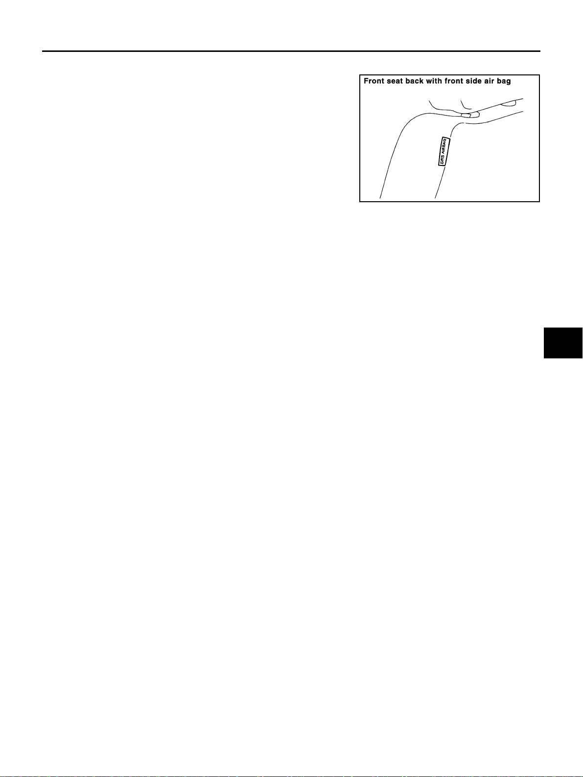
Front Side Air Bag AHS000QH
Front side air bag is built-in type.
The front seatbacks with built-in type side air bag have the labels
shown in figure at right.
A
B
C
PHIA0039E
D
E
F
G
SRS
I
J
K
Revision: 2005 March 2005 X-Trail
SRS-5
L
M

TROUBLE DIAGNOSIS
TROUBLE DIAGNOSIS PFP:00004 Trouble Diagnosis Introduction AHS000QI
CAUTION:
● Do not use electrical test equipme nt on any circuit related to the SRS unle ss instructed to in this
Service Manual. SRS wiring harness can be identified by yellow and/or oran ge harnesses or harness connector.
● Do not attempt to repair, splice or modify the SRS wiring harness. If the harness is damaged,
replace it with a new one.
● Keep ground portion clean.
DIAGNOSIS FUNCTION
The SRS self-diagnosis results can be rea d by using “AIR BAG” warning l amp and/or CONSULT-II.
The User mode is exclusively prepared for the customer (driver). This mode warns the driver of a system malfunction through the operation of the “AIR BAG” warning lamp.
The Diagnosis mode allows the technician to locate and inspect the malfunctioning part.
The mode applications for the “AIR BAG” war ning lamp and CONSULT-II are as follows:
User mode Diagnosis mode Display type
“AIR BAG” warning lamp X X ON-OFF operation
CONSULT-II — X Monitoring
NOTE:
Seat belt pre-tensioner malfunction is indicated by “AIR BAG” warning lamp.
HOW TO PERFORM TROUBLE DIAGNOSES FOR QUICK AND ACCURATE REPAIR
A good understanding of the malfunction conditions can make troubleshooting faster and more accurate.
In general, each customer feels differently about a malfunction. It is important to fully understand the symptoms or conditions for a customer complaint.
Information from Customer
WHAT..... Vehicle model
WHEN..... Date, Frequencies
WHERE..... Road conditions
HOW..... Operating conditions, Symptoms
Preliminary Check
Check that the following parts are in good order.
● Battery (R efer to SC-4, "How to Handle Battery" .)
● Fuse (Refer to SRS-9, "Wiring Diagram — SRS —" .)
● System compon ent-to-harne ss connections
Revision: 2005 March 2005 X-Trail
SRS-6
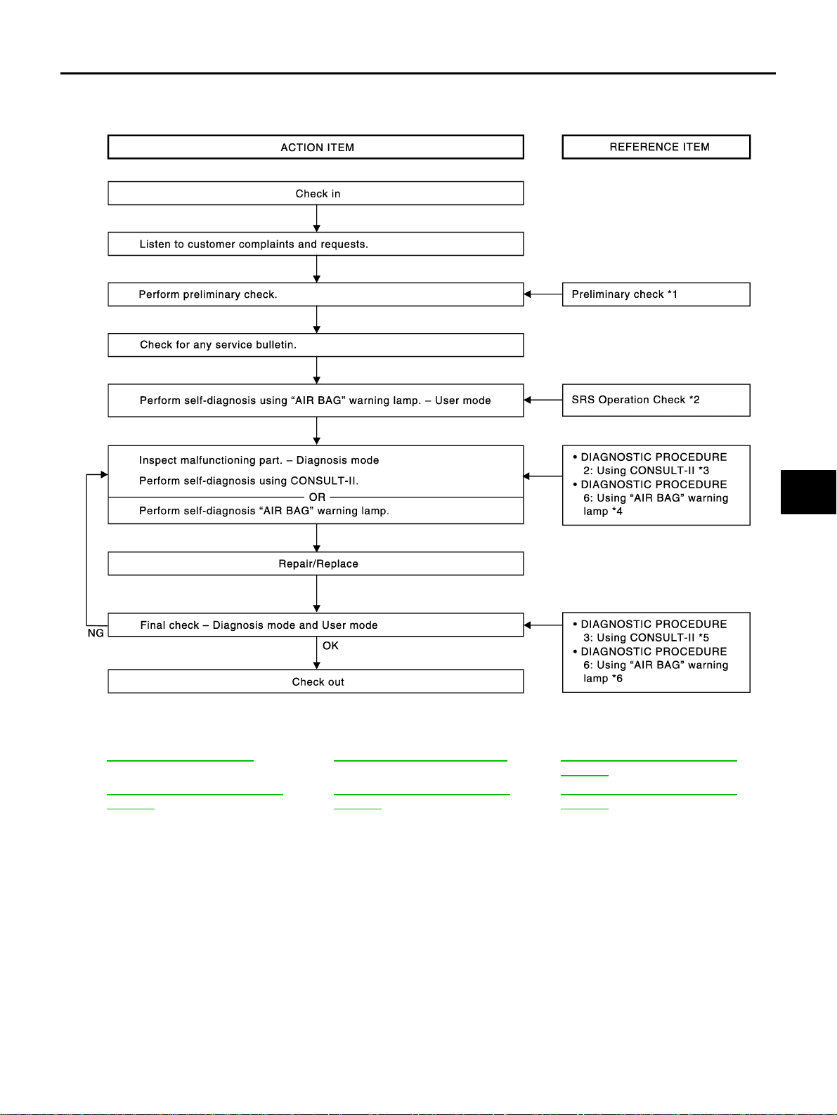
WORK FLOW
TROUBLE DIAGNOSIS
A
B
C
D
E
F
G
PHIA0217E
*1: SRS-6, "Preliminary Check".*2:SRS-13, "SRS Operation Check".*3:SRS-15, "DIAGNOSTIC PROCE-
DURE 2".
*4: SRS-24, "DIAGNOSTIC PROCE-
DURE 6".
*5: SRS-19, "
DURE 3".
DIAGNOSTIC PROCE-
*6: SRS-24, "
DURE 6".
DIAGNOSTIC PROCE-
SRS
I
J
K
L
M
Revision: 2005 March 2005 X-Trail
SRS-7
TROUBLE DIAGNOSIS
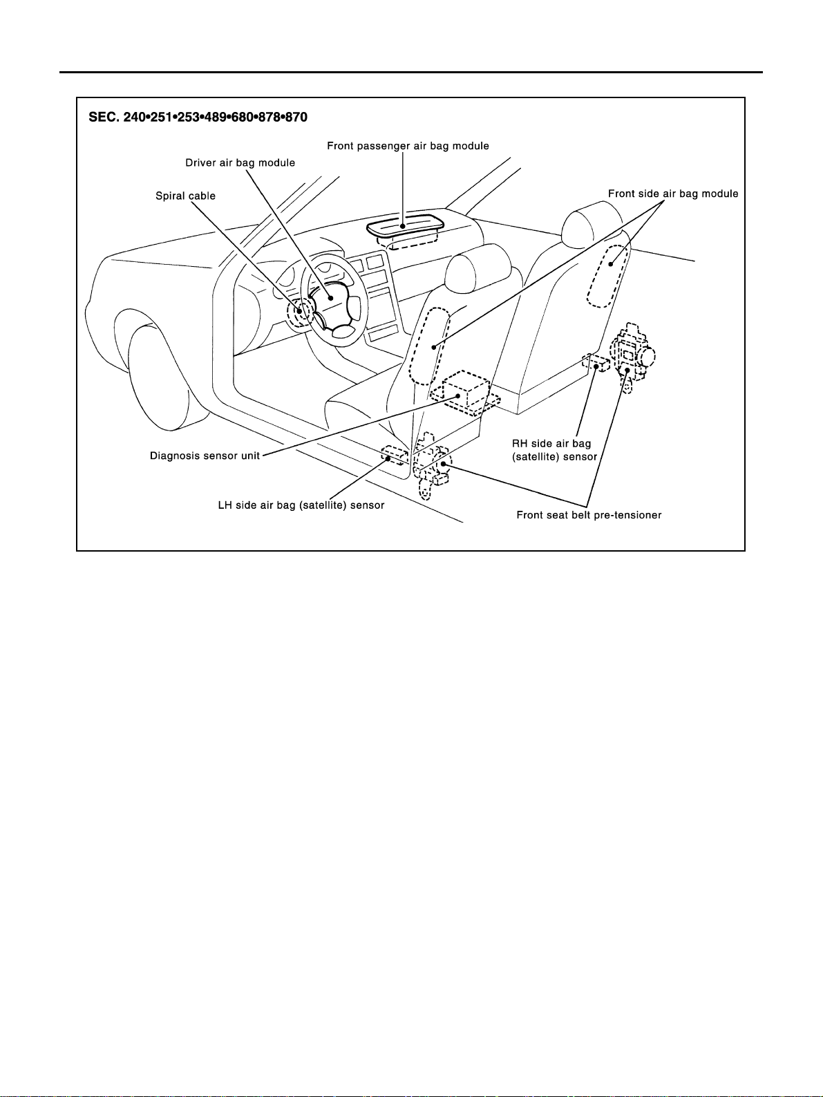
Component Parts Location AHS000QJ
PHIA0020E
Revision: 2005 March 2005 X-Trail
SRS-8
TROUBLE DIAGNOSIS
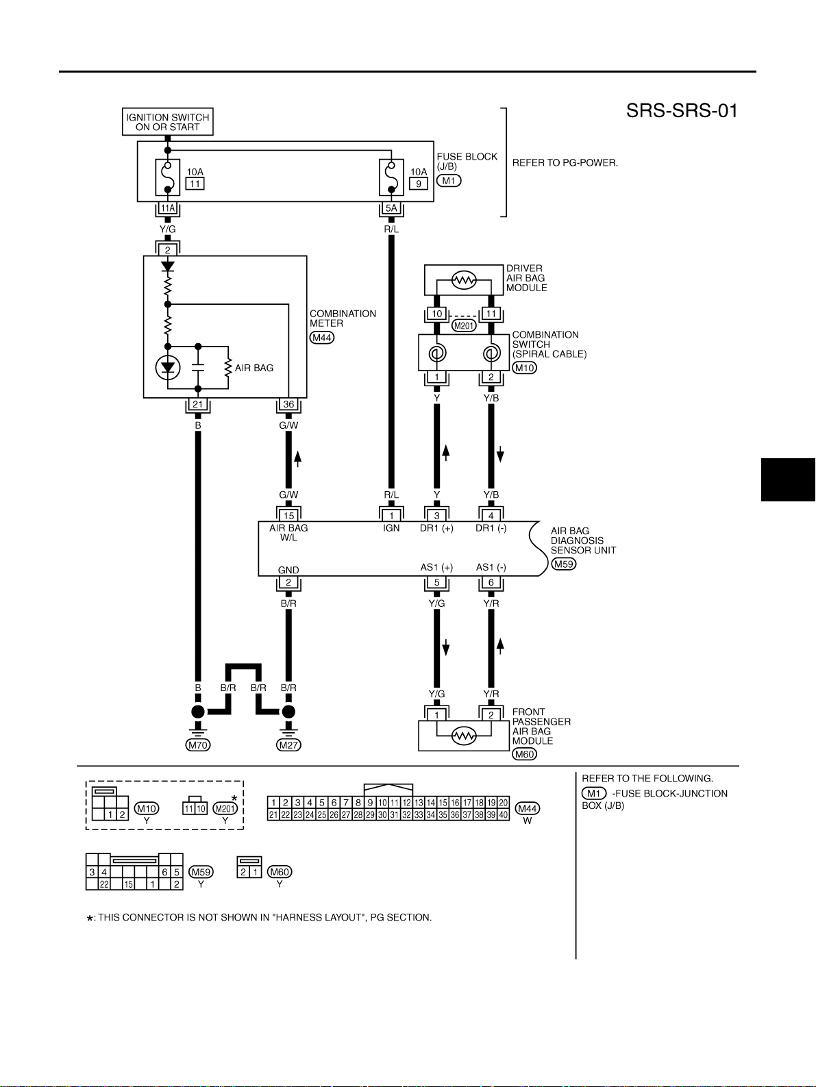
Wiring Diagram — SRS — AHS000QK
A
B
C
D
E
F
G
SRS
I
J
K
L
M
THWA0031E
Revision: 2005 March 2005 X-Trail
SRS-9

TROUBLE DIAGNOSIS
THWA0032E
Revision: 2005 March 2005 X-Trail
SRS-10
TROUBLE DIAGNOSIS
CONSULT-II Function AHS000QM
DIAGNOSIS MODE FOR CONSULT-II
● “SELF-DIAG [CURRENT]”
A current Self-diagnosis result (also indicated by the number of warning lamp flashes in the Diagnosis
mode) is displaye d on the CONSULT-II screen in real time. This refe rs to a malfun ctioning part requiring
repairs.
● “SELF-DIAG [PAST]”
Diagnosis results previously stored in the memory are displayed on the CONSULT-II screen. The stored
results ar e not erased until memory erasing is executed.
● “TROUBLE DIAG RECORD”
With TROUBLE DI AG RECORD, diagnosis results prev iously erased by a reset operatio n can be displayed on the CONSULT-II screen.
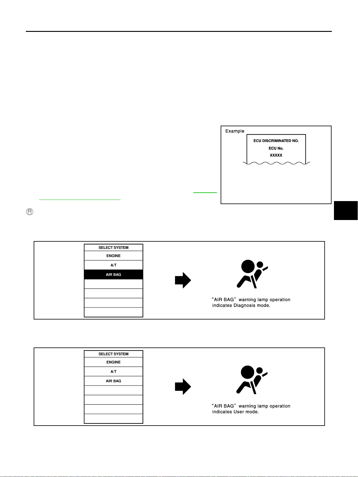
● “ECU DISCRIMINATED NO.”
The diagnosis sensor unit for each vehicle model is assigned
with its own, individual classification number. This number will
be displayed on the CONSULT-II screen, as shown. When
replacing the dia gnosis sens or unit, refe r to the part number fo r
the compatibility. After installation, replacement with a correct
unit can be checked by confirming this classification number on
the CONSULT-II screen.
After repair, make sure the discriminated number of diagnosis
sensor unit installed to vehicle are same. Refer to SRS-39,
"ECU DISCRIMINATED NO. " .
PHIA0218E
A
B
C
D
E
F
G
HOW TO CHANGE SELF-DIAGNOSIS MODE WITH CONSULT-II
From User Mode to Diagnosis Mode
After selecting “AIR B AG” on the “SELECT SYSTEM” screen, U ser mo de au tom at ic ally cha ng es to Di ag no si s
mode.
SRS803
From Diagnosis Mode to User Mode
To return to User mode from Diagnosis mode, touch “BACK” key of CONSULT-II until “SELECT SYSTEM”
appears, then diagnosis mode automatically changes to User mode.
SRS
I
J
K
L
M
SRS804
Revision: 2005 March 2005 X-Trail
SRS-11
TROUBLE DIAGNOSIS
HOW TO ERASE SELF-DIAGNOSIS RESULTS
● “SELF-DIAG [CURRENT]”
A current Self-diagnosis result is displayed on the CONSULT-II screen in real time.
After the malfunction is repaired completely, no malfunction is detected on “SELF-DIAG [CURRENT]”.
● “SELF-DIAG [PAST]”
Return to the “SELF-DIAG [CURRENT]” CONSULT-II screen by touching “BACK” key of CONSULT-II and
select “SELF-DIAG [CURRENT]” in SELECT DIAG MODE. Touch “ERASE” in “SELF-DIAG [CURRENT]”
mode.
NOTE:
If the memory of the m al fun ction in “SELF-DIAG [ PAST]” is not era sed, the User mode sho w s th e s y ste m
malfunction by the operat ion of the warning lamp even if the malfunction is repaired c ompletely.
● “TROUBLE DIAG RECORD”
The memory of “TROUBLE DIAG RECORD” cannot be erased.
SRS701
Self-Diagnosis Function (Without CONSULT-II) AHS000QN
● The reading of these results is accomplished “User mode” and “Diagnosis mode”.
● After a malfunction is repaired, turn ignition s witc h ON . Diag no s is m o de retu rns to th e Us er m od e. At th at
time, the self-diagnostic result is cleared.
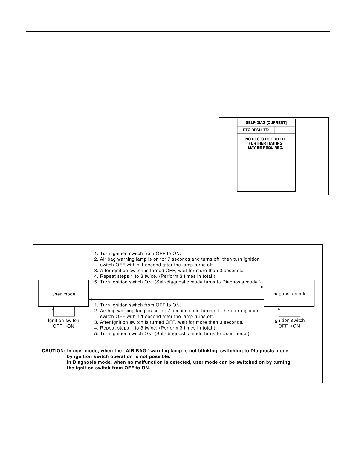
HOW TO CHANGE SELF-DIAGNOSIS MODE WITHOUT CONSULT-II
PHIA0709E
HOW TO ERASE SELF-DIAGNOSIS RESULTS
After a malfunction is repaired, turn the ignition switch OFF for at least one second, then back ON. Diagnosis
mode returns to the User mode. At that time, the self-diagnostic result is cleared.
Revision: 2005 March 2005 X-Trail
SRS-12

TROUBLE DIAGNOSIS
SRS Operation Check AHS000QO
DIAGNOSTIC PROCEDURE 1
Checking Air Bag Operation by Using “AIR BAG” Warning Lamp — User Mode
1. Turn the ignition switch from OFF to ON, and check that the air bag warning lamp blinks.
2. Compar e t he SR S ai r bag w a rn ing la mp b li nk in g p at t ern w ith th e
examples.
A
B
C
D
BF-1845D
E
F
G
SRS
I
J
K
L
Revision: 2005 March 2005 X-Trail
SRS-13
M
Loading...