


 Loading...
MANUAL TRANSAXLE
SECTION MT
GI
MA
EM
LC
EC
CONTENTS
FE
PREPARATION ............................................................... |
2 |
Special Service Tools .................................................. |
2 |
Commercial Service Tools ........................................... |
4 |
NOISE, VIBRATION AND HARSHNESS (NVH) |
|
TROUBLESHOOTING ..................................................... |
6 |
NVH Troubleshooting Chart......................................... |
6 |
DESCRIPTION ................................................................. |
7 |
Cross-sectional View ................................................... |
7 |
DOUBLE-CONE SYNCHRONIZER .............................. |
8 |
ON-VEHICLE SERVICE .................................................. |
9 |
Replacing Oil Seal ....................................................... |
9 |
DIFFERENTIAL OIL SEAL .......................................... |
9 |
STRIKING ROD OIL SEAL ......................................... |
9 |
Position Switch Check ............................................... |
10 |
BACK-UP LAMP SWITCH ........................................ |
10 |
PNP SWITCH .......................................................... |
10 |
Viscous Coupling Check............................................ |
11 |
REMOVAL AND INSTALLATION ................................. |
12 |
Removal..................................................................... |
12 |
Installation.................................................................. |
14 |
- QG ENGINE -........................................................ |
14 |
Installation.................................................................. |
15 |
- SR ENGINE - ........................................................ |
15 |
OVERHAUL ................................................................... |
16 |
Transaxle Gear Control ............................................. |
16 |
Case Components ..................................................... |
17 |
Gear Components ..................................................... |
18 |
Shift Control Components ......................................... |
19 |
Final Drive Components ............................................ |
20 |
DISASSEMBLY.............................................................. |
21 |
Transaxle Case.......................................................... |
21 |
Clutch Housing .......................................................... |
23 |
REPAIR FOR COMPONENT PARTS ........................... |
27 |
Input Shaft and Gears ............................................... |
27 |
DISASSEMBLY........................................................ |
27 |
INSPECTION........................................................... |
28 |
ASSEMBLY ............................................................. |
29 |
Mainshaft and Gears ................................................. |
32 |
DISASSEMBLY........................................................ |
32 |
INSPECTION........................................................... |
33 |
CL |
ASSEMBLY ............................................................. |
35 |
|
Final Drive.................................................................. |
40 |
|
PRE-INSPECTION ................................................... |
40 |
|
DISASSEMBLY........................................................ |
41 |
AT |
INSPECTION........................................................... |
42 |
|
ASSEMBLY ............................................................. |
43 |
|
Shift Control Components ......................................... |
46 |
AX |
INSPECTION........................................................... |
46 |
|
ASSEMBLY.................................................................... |
47 |
|
Clutch Housing .......................................................... |
47 |
SU |
Transaxle Case.......................................................... |
51 |
|
SERVICE DATA AND SPECIFICATIONS (SDS) ......... |
56 |
|
General Specifications............................................... |
56 |
BR |
TRANSAXLE ........................................................... |
56 |
|
FINAL GEAR ........................................................... |
56 |
|
Gear End Play ........................................................... |
57 |
ST |
Clearance Between Baulk Ring and Gear ................ |
57 |
|
3RD, 4TH, 5TH, REVERSE BAULK RING.................. |
57 |
|
1ST AND 2ND BAULK RING .................................... |
57 |
RS |
Available Snap Rings ................................................ |
57 |
|
SNAP RING............................................................. |
57 |
BT |
Available C-rings........................................................ |
58 |
|
4TH INPUT GEAR C-RING ....................................... |
58 |
|
5TH INPUT GEAR REAR C-RING............................. |
58 |
HA |
MAINSHAFT C-RING ............................................... |
58 |
|
Available Adjusting Shims ......................................... |
59 |
|
INPUT SHAFT REAR BEARING ADJUSTING |
|
SC |
SHIM ...................................................................... |
59 |
|
MAINSHAFT ADJUSTING SHIM................................ |
60 |
|
MAINSHAFT REAR BEARING ADJUSTING SHIM ...... |
60 |
EL |
Available Thrust Washer............................................ |
61 |
|
MAINSHAFT THRUST WASHER............................... |
61 |
|
Available Washers ..................................................... |
61 |
IDX |
DIFFERENTIAL SIDE GEAR THRUST WASHER........ |
61 |
|
Available Shims - Differential Side Bearing |
|
|
Preload and Adjusting Shim ...................................... |
62 |
|
BEARING PRELOAD ............................................... |
62 |
|
DIFFERENTIAL SIDE BEARING ADJUSTING |
|
|
SHIMS .................................................................... |
62 |
|

PREPARATION
Special Service Tools
Special Service Tools
NIMT0001
The actual shapes of Kent-Moore tools may differ from those of special service tools illustrated here.
Tool number |
|
|
(Kent-Moore No.) |
Description |
|
Tool name |
|
|
|
|
|
KV38107700 |
|
Measuring turning torque of final drive assembly |
(J39027) |
|
Measuring total turning torque |
Preload adapter |
|
Measuring clearance between side gear and differ- |
|
|
ential case with washer |
|
NT087 |
Selecting differential side bearing adjusting shim |
|
[Use with KV38106000 (J34291-B).] |
|
|
|
|
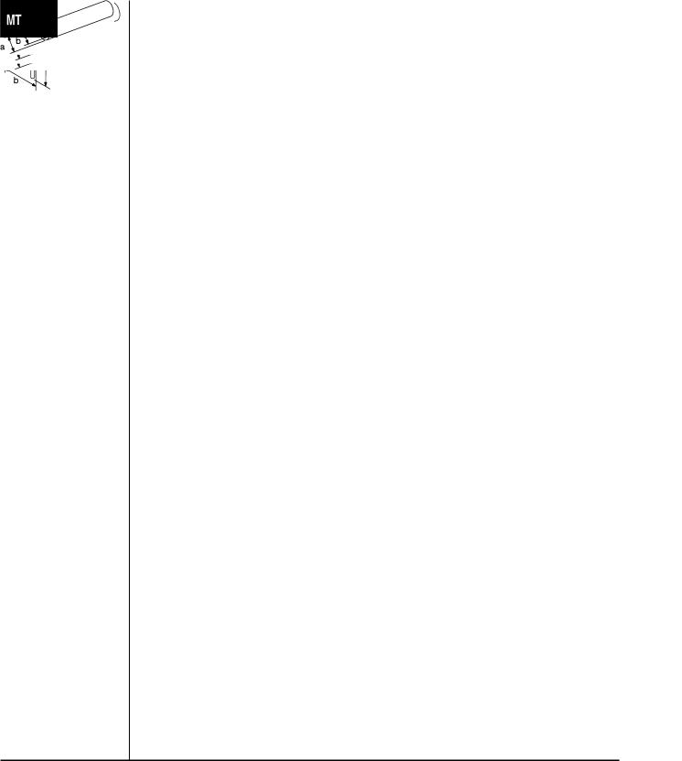
KV38106000 |
|
Selecting differential side bearing adjusting shim |
(J34291-B) |
|
[Use with KV38107700 (J39027).] |
Height gauge adapter |
|
a: 140 mm (5.51 in) |
(differential side bearing) |
|
b: 40 mm (1.57 in) |
|
|
c: 16 mm (0.63 in) dia. |
|
|
d: M8 × 1.25P |
|
NT418 |
|
KV32101000 |
|
Removing and installing retaining pin |
(J25689-A) |
|
Removing and installing lock pin |
Pin punch |
|
Removing selector shaft |
|
|
Removing welch plug |
|
|
a: 4 mm (0.16 in) dia. |
|
NT410 |
|
|
|
|
KV31100300 |
|
Removing and installing retaining pin |
(J25689-A) |
|
a: 4.5 mm (0.177 in) dia. |
Pin punch |
|
|
|
NT410 |
|
|
|
|
ST30031000 |
|
Removing 3rd, 5th input gear |
(J22912-O1) |
|
Removing 3rd & 4th and 5th & Rev synchronizer |
Puller |
|
hub |
|
|
Removing mainshaft rear bearing |
|
|
Removing 2nd gear, 5th gear bush |
|
|
Removing 1st & 2nd synchronizer hub, 1st and |
|
|
4th main gear |
|
|
Removing and installing differential side bearing |
|
NT411 |
a: 90 mm (3.54 in) dia. |
|
|
b: 50 mm (1.97 in) dia. |
|
|
|
ST30021000 |
|
Removing input shaft front and rear bearing |
(J22912-O1) |
|
Installing input shaft front and rear bearing |
Puller |
|
Installing 5th input gear, 3rd main gear and 4th |
|
|
main gear |
|
|
Installing 1st & 2nd, 3rd & 4th and 5th & Rev syn- |
|
|
chronizer hub |
|
|
Installing 2nd gear bush, 5th gear bush, Rev gear |
|
|
bush |
|
NT411 |
Installing mainshaft rear bearing |
|
a: 110 mm (4.33 in) dia. |
|
|
|
b: 68 mm (2.68 in) dia. |
|
|
|
MT-2
|
PREPARATION |
|
Special Service Tools (Cont’d) |
|
|
|
|
Tool number |
|
(Kent-Moore No.) |
Description |
Tool name |
|
|
|
ST33061000 |
Removing differential side bearing |
(J8107-2) |
a: 39 mm (1.54 in) dia. |
Drift |
b: 29.5 mm (1.16 in) dia. |
|
NT073 |
|
|
ST33290001 |
Removing idler gear bearing outer race |
(J34286) |
a: 250 mm (9.84 in) |
Puller |
b: 160 mm (6.30 in) |
|
NT414 |
|
ST33230000 |
|
Removing differential oil seal |
(J25805-O1) |
|
Installing differential side bearing |
Drift |
|
a: 51 mm (2.01 in) dia. |
|
|
b: 28.5 mm (1.122 in) dia. |
|
NT084 |
|
|
|
|
ST30720000 |
|
Installing differential side bearing outer race |
(J25405) |
|
(F70A and clutch housing side of F70V) |
Drift |
|
a: 77 mm (3.03 in) dia. |
|
|
b: 55.5 mm (2.185 in) dia. |
|
NT115 |
|
|
|
|
ST22350000 |
|
Installing input shaft front and rear bearing |
(J25678-O1) |
|
a: 34 mm (1.34 in) dia. |
Drift |
|
b: 28 mm (1.10 in) dia. |
|
NT065 |
|
ST22452000 |
|
Installing 3rd and 4th main gear |
(J34335) |
|
Installing 5th gear bush |
Drift |
|
Installing 5th & Rev synchronizer hub |
|
|
Installing Rev gear bush |
|
|
Installing mainshaft rear bearing |
|
NT065 |
a: 45 mm (1.77 in) dia. |
|
b: 36 mm (1.42 in) dia. |
|
|
|
|
|
|
|
ST37750000 |
|
Installing input shaft oil seal |
(J34335) |
|
Installing 5th synchronizer |
Drift |
|
Installing mainshaft rear bearing |
|
|
Installing 5th main gear |
|
|
Installing 3rd & 4th synchronizer hub |
|
|
Installing striking rod oil seal |
|
NT065 |
Installing clutch housing dust seal |
|
a: 40 mm (1.57 in) dia. |
|
|
|
|
|
|
b: 31 mm (1.22 in) dia. |
GI
MA
EM
LC
EC
FE
CL
AT
AX
SU
BR
ST
RS
BT
HA
SC
EL
IDX
MT-3
|
PREPARATION |
Special Service Tools (Cont’d) |
|
|
|
|
|
Tool number |
|
(Kent-Moore No.) |
Description |
Tool name |
|
|
|
ST30621000 |
Installing differential side bearing outer race |
(J35869) |
[Use with ST30611000 (J25742-1).] |
Drift |
(F70A and clutch housing side of F70V) |
|
a: 79 mm (3.11 in) dia. |
|
b: 59 mm (2.32 in) dia. |
|
NT073 |
|
|
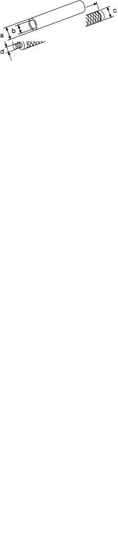
ST30611000 |
Installing differential side bearing outer race |
(J25742-1) |
[Use with ST30621000 (J35869).] |
Drift handle |
a: 15 mm (0.59 in) |
|
b: 335 mm (13.19 in) |
|
c: 25 mm (0.98 in) dia. |
|
d: M12 × 1.5P |
|
NT419 |
|
|
|
Commercial Service Tools |
|
NIMT0002 |
Tool name |
Description |
|
|
Drift |
Installing differential side bearing inner race |
|
(F70A and except viscous coupling side of F70V) |
|
a: 56 mm (2.20 in) dia. |
|
b: 50.5 mm (1.988 in) dia. |
|
NT065 |
|
|
Drift |
Installing differential oil seal |
|
(F70V transaxle case side) |
|
a: 94 mm (3.70 in) dia. |
|
b: 72 mm (2.83 in) dia. |
|
NT065 |
|
|
Drift |
Installing differential side bearing outer race |
|
(F70V viscous coupling side) |
|
a: 104 mm (4.09 in) dia. |
|
b: 98 mm (3.86 in) dia. |
|
NT065 |
|
|
Drift |
Installing differential side bearing inner race |
|
(F70V viscous coupling side) |
|
a: 91 mm (3.58 in) dia. |
|
b: 81 mm (3.19 in) dia. |
|
NT065 |
|
|
Drift |
Removing input shaft rear bearing |
|
Removing mainshaft rear bearing |
|
a: 22 mm (0.87 in) dia. |
|
b: 16 mm (0.63 in) dia. |
|
NT065 |
|
|
Drift |
Installing differential oil seal |
|
(Transaxle case side of F70A and clutch housing |
|
side of F70V) |
|
a: 58 mm (2.28 in) dia. |
|
b: 50 mm (1.97 in) dia. |
|
NT065 |
|
|
MT-4

|
PREPARATION |
|
Commercial Service Tools (Cont’d) |
|
|
|
|
Tool name |
Description |
|
|
Drift |
Installing differential oil seal |
|
(Clutch housing side of F70A) |
|
a: 54 mm (2.13 in) dia. |
|
b: 50 mm (1.97 in) dia. |
|
NT065 |
|
|
Drift |
Installing 2nd gear bush |
|
a: 38 mm (1.50 in) dia. |
|
b: 33 mm (1.30 in) dia. |
|
NT065 |
Drift |
Installing 3rd & 4th and 1st & 2nd synchronizer |
|
hub |
|
Installing mainshaft front bearing |
|
a: 50 mm (1.97 in) dia. |
|
b: 41 mm (1.61 in) dia. |
|
NT065 |
|
|
Drift |
Installing input shaft oil seal |
|
Installing 5th input gear |
|
a: 39 mm (1.54 in) dia. |
|
b: 30 mm (1.18 in) dia. |
|
NT065 |
|
|
GI
MA
EM
LC
EC
FE
CL
AT
AX
SU
BR
ST
RS
BT
HA
SC
EL
IDX
MT-5

NIMT0003
NOISE, VIBRATION AND HARSHNESS (NVH) TROUBLESHOOTING
NVH Troubleshooting Chart
NVH Troubleshooting Chart
NIMT0003S01
Use the chart below to help you find the cause of the symptom. The numbers indicate the order of the inspection. If necessary, repair or replace these parts.
|
|
|
|
|
|
|
|
|
|
|
|
|
|
|
|
|
|
M/TOil”. |
|
|
|
|
|
|
|
|
|
|
|
Reference page |
|
,20“Checking |
|
MT-17 |
MT-17 |
MT-17 |
MT-16 |
MT-19 |
MT-19 |
MT-18 |
MT-18 |
MT-18 |
MT-18 |
|
|
|
|
|
|
|
|
|
|
|
|
|
|
||
|
|
|
Refer to MA- |
|
|
|
|
|
|
|
|
|
|
|
|
|
|
|
|
|
|
|
|
|
|
|
|
|
|
|
|
|
|
|
(Damaged)GASKET |
damaged)or(WornSEALOIL |
damaged)or(WornRING-O |
(Worn)RODCONTROL |
(Worn or damaged) |
(Worn)FORKSHIFT |
damaged)or(WornGEAR |
damaged)or(WornBEARING |
damaged)or(WornRINGBAULK |
INSERTSHIFTINGSPRING,INSERT(Damaged) |
SUSPECTED PARTS |
low.)islevel(Oil |
oil)(Wrong |
high.)islevel(Oil |
ANDSPRINGRETURNPLUGCHECKCHECK BALL |
||||||||||
|
|
|
|
|
|
|
|
|
|
|
|
|
||
(Possible cause) |
|
|
|
|
|
|
|
|
|
|
|
|
|
|
|
|
|
|
|
|
|
|
|
|
|
|
|
|
|
|
Noise |
1 |
2 |
|
|
|
|
|
|
|
3 |
3 |
|
|
|
|
|
|
|
|
|
|
|
|
|
|
|
|
|
Symptom |
Oil leakage |
|
3 |
1 |
2 |
2 |
2 |
|
|
|
|
|
|
|
|
|
|
|
|
|
|
|
|
|
|
|
|
|
|
Hard to shift or will not shift |
|
1 |
1 |
|
|
|
2 |
|
|
|
|
3 |
3 |
|
|
|
|
|
|
|
|
|
|
||||||
|
|
|
|
|
|
|
|
|
|
|
|
|
|
|
|
Jumps out of gear |
|
|
|
|
|
|
1 |
2 |
3 |
3 |
|
|
|
|
|
|
|
|
|
|
|
|
|
|
|
|
|
|
MT-6
NIMT0004
DESCRIPTION
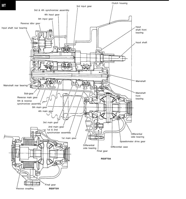
Cross-sectional View
Cross-sectional View
NIMT0004S01
GI
MA
EM
LC
EC
FE
CL
AT
AX
SU
BR
ST
RS
BT
HA
SC
EL
IDX
SMT902D
MT-7
DESCRIPTION
Cross-sectional View (Cont’d)
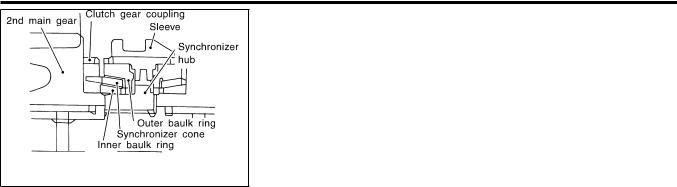
DOUBLE-CONE SYNCHRONIZER
NIMT0004S0101
Double-cone synchronizer is adopted for 1st and 2nd gears to reduce operating force of the shift lever.
SMT837DA
MT-8
ON-VEHICLE SERVICE
Replacing Oil Seal
SMT563A
SMT126DB
WMT012
Replacing Oil Seal
NIMT0005
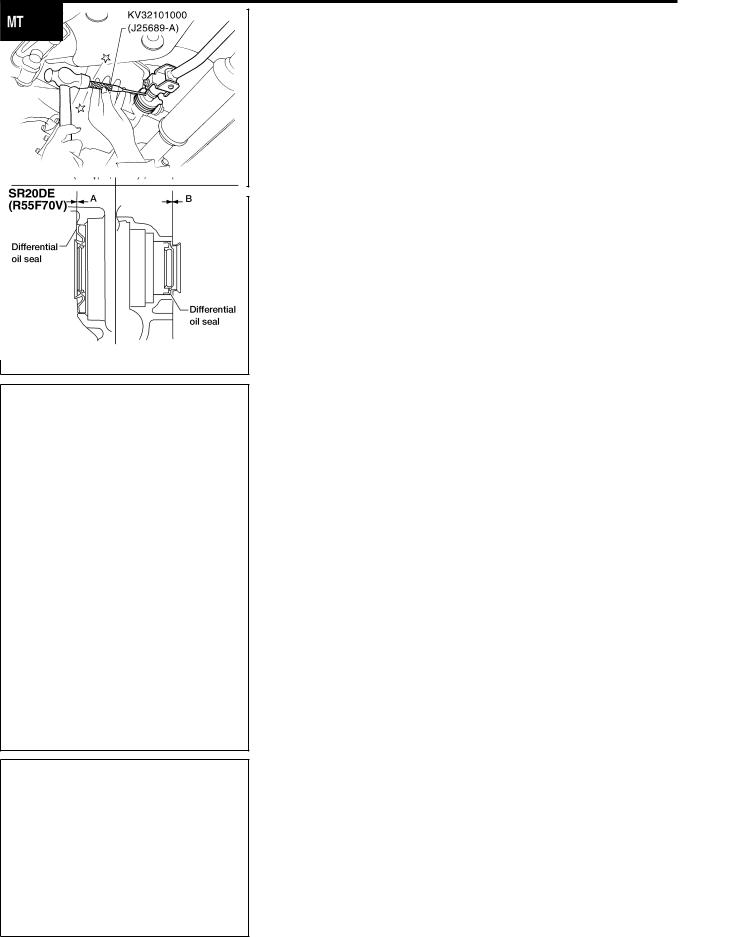
DIFFERENTIAL OIL SEAL |
GI |
|
1. |
NIMT0005S01 |
|
Remove drain plug and drain gear oil from transaxle. |
|
|
2. |
Remove drive shafts. Refer to AX-12, “Removal”. |
MA |
3. |
Remove differential oil seal using Tool. |
|
|
|
EM |
|
|
LC |
4. |
Install differential oil seal with a suitable tool. |
|
|
Apply multi-purpose grease to seal lip of oil seal before |
EC |
|
installing. |
|
5. |
Install drive shafts. Refer to AX-13, “Installation”. |
FE |
|
|
|
CL
Install differential oil seal so that dimension “A” and “B”
are within specifications. |
Unit: mm (in) |
AT |
|||
|
|
|
|
||
|
|
|
|
|
|
Item |
Model |
A |
B |
AX |
|
|
|
|
|
|
|
|
QG18DE |
|
|
|
|
|
|
|
|
|
|
|
SR20DE |
|
5.5 - 6.5 (0.217 - 0.256) |
|
SU |
Dimension |
(RS5F70A) |
0.5 (0.020) or less |
|
|
|
|
SR20DE |
|
0.5 (0.020) or less |
|
|
|
(RS5F70V) |
|
BR |
||
|
|
|
|
||
|
|
|
|
|
|
|
|
|
|
|
|
|
|
|
|
|
ST |
|
|
|
|
|
RS |
|
|
|
|
|
BT |
|
|
|
|
|
HA |
STRIKING ROD OIL SEAL
1.Remove transaxle control rod from yoke.
2.Remove retaining pin of yoke using Tool.
Be careful not to damage boot.
3.Remove the boot.
NIMT0005S02 SC
EL
IDX
SMT143DB
MT-9
ON-VEHICLE SERVICE
Replacing Oil Seal (Cont’d)
4.Remove striking rod oil seal with a suitable tool.
SMT566A
SMT570AA
SMT715BD
5.Install striking rod oil seal using Tool.
Apply multi-purpose grease to seal lip of oil seal before installing.
6.Install the boot.
7.Install yoke and retaining pin.
8.Connect the transaxle control rod to the yoke.
Position Switch Check
NIMT0006
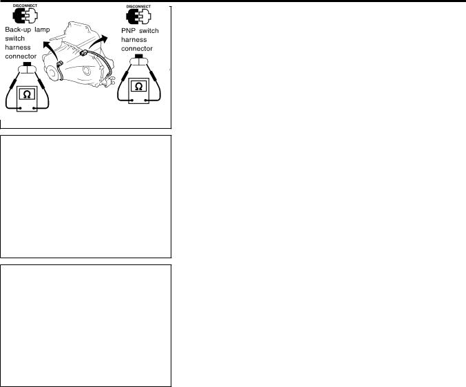
BACK-UP LAMP SWITCH
Check continuity. |
NIMT0006S01 |
|
|
||
|
|
|
|
Gear position |
Continuity |
|
|
|
|
Reverse |
Yes |
|
|
|
|
Except reverse |
No |
|
|
|
PNP SWITCH
Check continuity. |
NIMT0006S02 |
|
|
||
|
|
|
|
Gear position |
Continuity |
|
|
|
|
Neutral |
Yes |
|
|
|
|
Except neutral |
No |
|
|
|
MT-10
ON-VEHICLE SERVICE
Viscous Coupling Check
Viscous Coupling Check
NIMT0039
1.Apply parking brake firmly and place shift lever in the neutral
position.
2.Jack up front wheels.
3.Rotate one front wheel and check turning direction of the other front wheel.
Turning direction of the two wheels is opposite:
The viscous coupling is not functioning normally.
Turning direction of the two wheels is the same:
If differential side gear and pinion mate gear thrust washers are OK, viscous coupling is functioning normally.
LMT022
GI
MA
EM
LC
EC
FE
CL
AT
AX
SU
BR
ST
RS
BT
HA
SC
EL
IDX
MT-11
NIMT0007
REMOVAL AND INSTALLATION
Removal
Removal
NIMT0007S01
WMT009
1.Remove battery negative terminal.
2.Remove air cleaner and air duct.
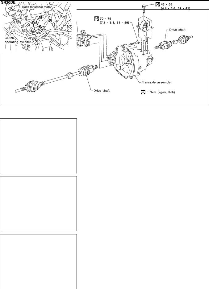
3.Remove clutch operating cylinder from transaxle. Refer to CL-11, “Removal”.
4.Disconnect back-up lamp switch, speedometer sensor, PNP switch and ground harness connectors.
WMT010
5.Remove starter motor from transaxle. Refer to SC-11, “Removal and Installation”.
WMT008
WMT011
MT-12
REMOVAL AND INSTALLATION
Removal (Cont’d)
6.Remove air breather hose.
SMT132D
7.Remove shift control rod and support rod from transaxle.
8.Remove the drain plug and drain gear oil from transaxle.
9.Draw out drive shafts from transaxle. Refer to AX-12, “Removal”.
WMT005
GI
MA
EM
LC
EC
FE
CL
|
10. Support engine by placing a jack under oil pan. |
AT |
|
CAUTION: |
|
|
Do not place jack under oil pan drain plug. |
|
|
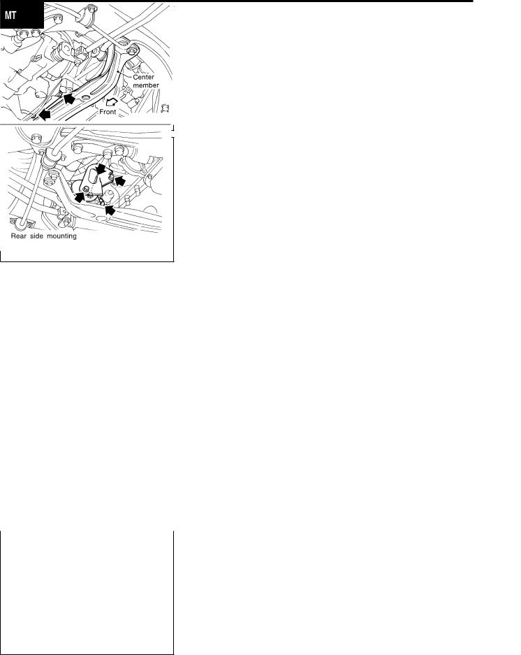
11. Remove LH side and rear side mounting bolts. |
AX |
|
|
|
|
|
SU |
|
|
BR |
|
|
ST |
|
|
RS |
|
|
BT |
|
|
HA |
WMT007 |
|
|
|
12. Remove lower housing bolts. |
SC |
|
||
|
|
EL |
|
|
IDX |
SMT658B
MT-13

REMOVAL AND INSTALLATION
Removal (Cont’d)
13.Remove bolts securing transaxle.
14.Lower transaxle while supporting it with a jack.
SMT659B
Installation
NIMT0007S03
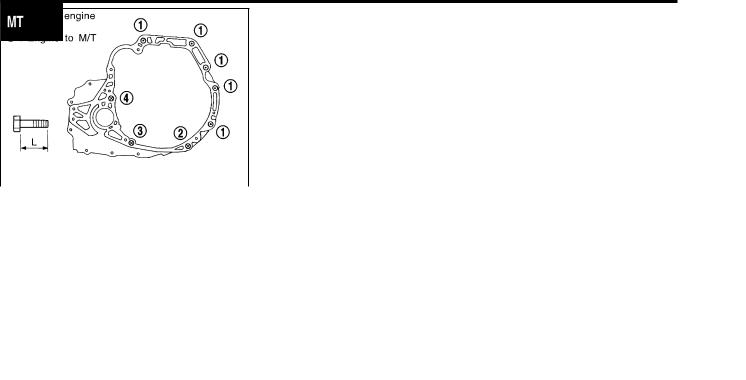
— QG ENGINE —
NIMT0007S0301
Tighten starter motor to transaxle.
: 31 - 42 N·m (3.2 - 4.3 kg-m, 23 - 31 ft-lb)
Tighten LH and rear mounts to the specified torque. Refer to EM-50, “REMOVAL”.
Install transaxle and any part removed.
Check clutch cable adjustment. Refer to CL-17, “INSPECTION AND ADJUSTMENT”.
WMT018 |
|
|
Tightening torque |
“” mm (in) |
||
|
|
Bolt No. |
|
N·m (kg-m, ft-lb) |
||
|
|
|
|
|
|
|
|
|
|
|
|
|
|
|
1 |
|
|
30 - 40 (3.1 - 4.1, 22 - 30) |
50 (1.97) |
|
|
|
|
|
|
|
|
|
2 |
|
|
30 - 40 (3.1 - 4.1, 22 - 30) |
30 (1.18) |
|
|
|
|
|
|
|
|
|
3 |
|
|
16 - 21 (1.6 - 2.1, 12 - 15) |
25 (0.98) |
|
|
|
|
|
|
|
|
|
|
Front gusset to engine |
|
30 - 40 (3.1 - 4.1, 22 - 30) |
20 (0.79) |
|
|
|
|
|
|
|
|
|
|
Rear gusset to |
|
A |
16 - 21 (1.6 - 2.1, 12 - 15) |
17.5 (0.689) |
|
|
engine |
|
|
|
|
|
|
|
B |
20 (0.79) |
||
|
|
|
|
|
||
WMT019 |
|
|
|
|
|
|
|
|
|
|
|
|
|
MT-14
REMOVAL AND INSTALLATION
Installation
Installation
NIMT0007S02
— SR ENGINE —
NIMT0007S0201
Tighten bolts securing transaxle and install any part removed.
Tighten starter motor bolts.
|
|
: 41 - 52 N·m (4.2 - 5.3 kg-m, 30 - 38 ft-lb) |
|
||||
|
|
Bolt No. |
1 |
2 |
3 |
|
4 |
|
|
|
|
|
|
|
|
|
|
Q’ty |
5 |
|
1 |
|
|
|
|
|
|
|
|
|
|
|
|
L in mm (in) |
55 (2.17) |
35 (1.38) |
45 (1.77) |
|
65 (2.56) |
|
|
|
|
|
|
||
SMT134D |
Tightening torque |
70 - 79 |
30 - 40 |
|
70 - 79 |
||
|
|
|
|||||
|
|
(7.1 - 8.1, |
|
(7.1 - 8.1, |
|||
|
|
N·m (kg-m, ft-lb) |
(3.1 - 4.1, 22 - 30) |
|
|||
|
|
51 - 59) |
|
51 - 59) |
|||
|
|
|
|
|
|
||
|
|
|
|
|
|
|
|
GI
MA
EM
LC
EC
FE
CL
AT
AX
SU
BR
ST
RS
BT
HA
SC
EL
IDX
MT-15
NIMT0008
OVERHAUL
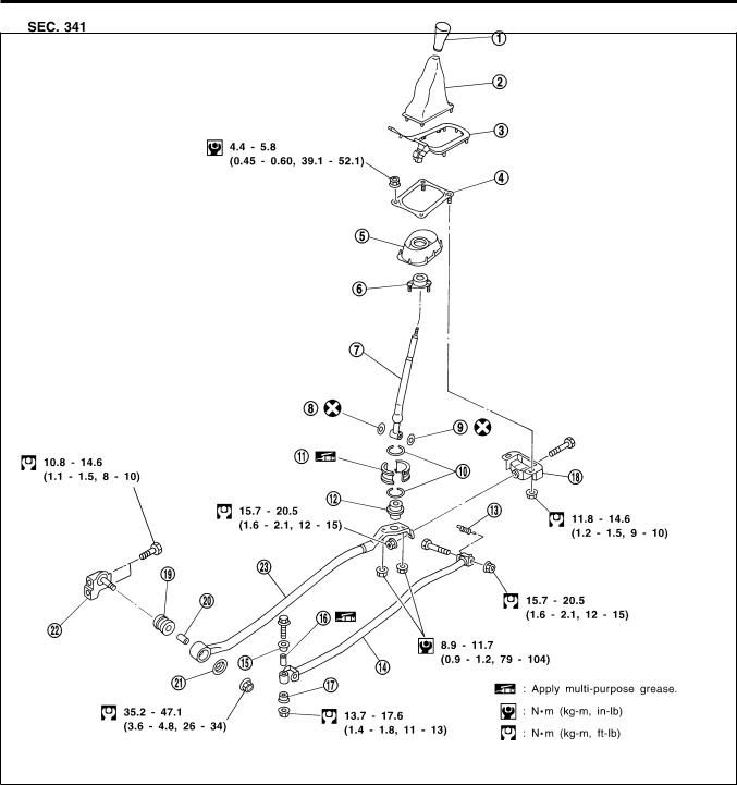
Transaxle Gear Control
Transaxle Gear Control
NIMT0008S01
SMT904D
1. |
Control lever knob |
9. |
O-ring |
17. |
Bushing |
2. |
Boot |
10. |
Ring spring |
18. |
Bracket |
3. |
Finisher |
11. |
Bearing seat |
19. |
Bushing |
4. |
Control lever bracket |
12. |
Seat |
20. |
Collar |
5. |
Dust cover |
13. |
Return spring |
21. |
Washer |
6. |
Socket |
14. |
Control rod |
22. |
Support rod bracket |
7. |
Control lever |
15. |
Bushing |
23. |
Support rod |
8. |
O-ring |
16. |
Collar |
|
|
MT-16

OVERHAUL
Case Components
Case Components
=NIMT0008S02
WMT014
1. |
Clutch housing |
13. |
O-ring |
25. |
Differential oil seal |
2. |
Dust seal |
14. |
Reverse idler gear shaft |
26. |
Drain plug |
3. |
Oil pocket |
15. |
Snap ring |
27. |
PNP switch |
4. |
Check plug |
16. |
Back-up lamp switch |
28. |
Transmission case |
5. |
Input shaft oil seal |
17. |
Filler plug |
29. |
Oil gutter |
6. |
Oil channel |
18. |
Side cover gasket |
30. |
Welch plug |
7. |
Mainshaft front bearing |
19. |
Side cover |
31. |
Boot |
8. |
Bearing retainer |
20. |
Welch plug |
32. |
Striking rod oil seal |
9. |
Reverse idler gear front thrust |
21. |
Mainshaft bearing snap ring |
33. |
Welch plug |
|
washer |
22. |
Mainshaft rear bearing adjusting |
34. |
Differential oil seal |
10. |
Reverse idler gear |
|
shim |
35. |
O-ring |
11. |
Reverse idler gear bearing |
23. |
O-ring |
36. |
Speedometer pinion |
12. |
Reverse idler gear rear thrust |
24. |
Rear cover |
|
|
|
washer |
|
|
|
|
GI
MA
EM
LC
EC
FE
CL
AT
AX
SU
BR
ST
RS
BT
HA
SC
EL
IDX
MT-17
OVERHAUL
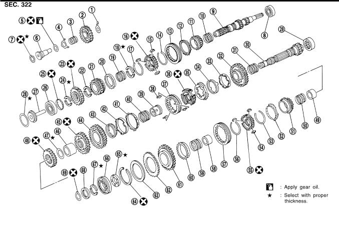
Gear Components
Gear Components
=NIMT0008S03
|
|
|
|
|
SMT641DA |
|
|
|
|
|
|
1. |
Reverse idler gear front thrust |
24. |
5th gear rear C-ring |
47. |
Mainshaft adjusting shim |
|
washer |
25. |
C-ring holder |
48. |
4th main gear |
2. |
Reverse idler gear |
26. |
Input shaft rear bearing |
49. |
5th gear bush |
3. |
Reverse idler gear bearing |
27. |
Oil channel |
50. |
5th gear needle bearing |
4. |
Reverse idle gear rear thrust |
28. |
Input shaft rear bearing adjusting |
51. |
5th main gear |
|
washer |
|
shim |
52. |
5th gear baulk ring |
5. |
O-ring |
29. |
Mainshaft front bearing |
53. |
Spread spring |
6. |
Reverse idler gear shaft |
30. |
Mainshaft |
54. |
Shifting insert |
7. |
Snap ring |
31. |
1st gear needle bearing |
55. |
5th & reverse synchronizer hub |
8. |
Input shaft front bearing |
32. |
1st main gear |
56. |
Spread spring |
9. |
Input shaft |
33. |
1st inner baulk ring |
57. |
Coupling sleeve |
10. |
3rd gear needle bearing |
34. |
1st synchronizer cone |
58. |
Reverse gear bush |
11. |
3rd input gear |
35. |
1st outer baulk ring |
59. |
Reverse gear needle bearing |
12. |
3rd gear baulk ring |
36. |
1st & 2nd synchronizer hub |
60. |
Reverse gear baulk ring |
13. |
Coupling sleeve |
37. |
Coupling sleeve |
61. |
Reverse main gear |
14. |
Spread spring |
38. |
Insert spring |
62. |
Sub-gear |
15. |
Shifting insert |
39. |
2nd gear bush |
63. |
Sub-gear washer |
16. |
3rd & 4th synchronizer hub |
40. |
2nd gear needle bearing |
64. |
Snap ring |
17. |
Spread spring |
41. |
2nd gear outer baulk ring |
65. |
Mainshaft thrust washer |
18. |
4th gear C-ring |
42. |
2nd gear synchronizer cone |
66. |
Mainshaft rear bearing |
19. |
4th gear needle bearing |
43. |
2nd inner baulk ring |
67. |
Mainshaft C-ring |
20. |
4th gear baulk ring |
44. |
2nd main gear |
68. |
C-ring holder |
21. |
4th input gear |
45. |
3rd main gear |
69. |
Snap ring |
22. |
5th gear front C-ring |
46. |
Spacer |
|
|
23. |
5th input gear |
|
|
|
|
MT-18
OVERHAUL
Shift Control Components
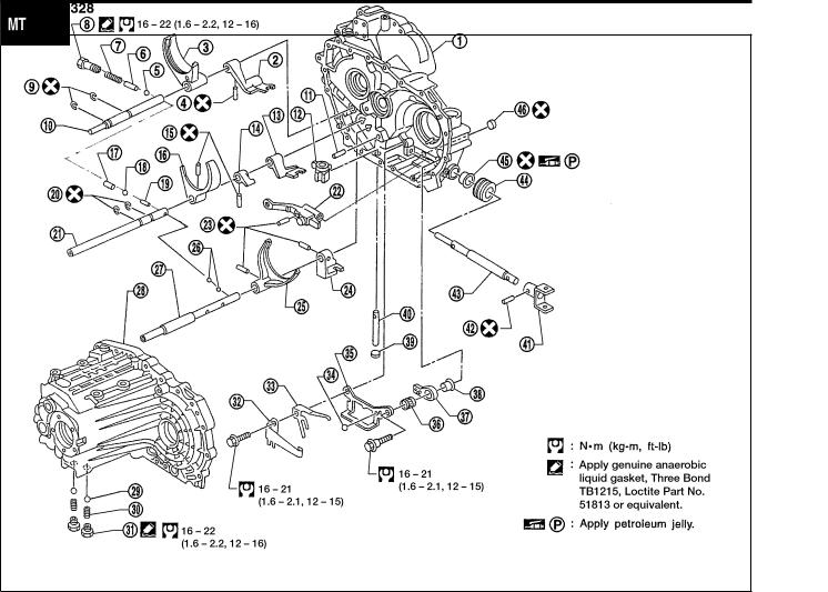
Shift Control Components
=NIMT0008S04
GI
MA
EM
LC
EC
FE
CL
AT
AX
SU
WMT015
1. |
Clutch housing |
17. |
Interlock plunger |
32. |
Select check leaf spring |
2. |
3rd & 4th bracket |
18. |
Check ball |
33. |
Return spring |
3. |
3rd & 4th shift fork |
19. |
Interlock pin |
34. |
Steel ball |
4. |
Retaining pin |
20. |
Stopper ring |
35. |
Reverse gate |
5. |
Check ball |
21. |
5th & reverse fork rod |
36. |
Return bearing |
6. |
Check pin |
22. |
Striking lever |
37. |
Selector arm |
7. |
Check spring |
23. |
Retaining pin |
38. |
Bushing |
8. |
Check plug |
24. |
1st & 2nd bracket |
39. |
Welch plug |
9. |
Stopper ring |
25. |
1st & 2nd shift fork |
40. |
Selector shaft |
10. |
3rd & 4th fork rod |
26. |
Check ball |
41. |
Striking yoke |
11. |
Selector shaft pin |
27. |
1st & 2nd fork rod |
42. |
Retaining pin |
12. |
Selector |
28. |
Transaxle case |
43. |
Striking rod |
13. |
5th & reverse bracket |
29. |
Check ball |
44. |
Dust boot |
14. |
Reverse switch bracket |
30. |
Check spring |
45. |
Striking rod oil seal |
15. |
Retaining pin |
31. |
Check plug |
46. |
Welch plug |
16. |
5th & reverse shift fork |
|
|
|
|
BR
ST
RS
BT
HA
SC
EL
IDX
MT-19
OVERHAUL
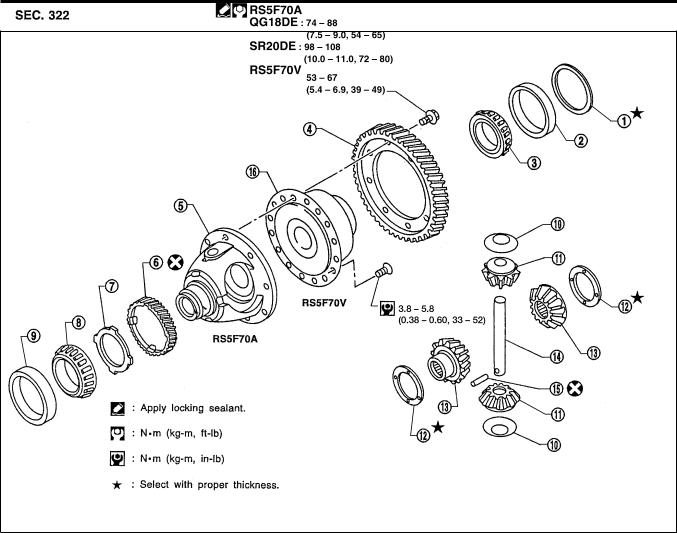
Final Drive Components
Final Drive Components
=NIMT0008S05
WMT016
1. |
Differential side bearing adjusting |
6. |
Speedometer drive gear |
12. |
Side gear thrust washer |
|
shim |
7. |
Speedometer stopper |
13. |
Side gear |
2. |
Differential side bearing outer race |
8. |
Differential side bearing |
14. |
Pinion mate shaft |
3. |
Differential side bearing |
9. |
Differential side bearing outer race |
15. |
Lock pin |
4. |
Final gear |
10. |
Pinion mate thrust washer |
16. |
Viscous coupling |
5. |
Differential case |
11. |
Pinion mate gear |
|
|
MT-20
Loading...