


 Loading...
I BODY
SECTION GW
GLASSES, WINDOW SYSTEM & MIRRORS
A
B
C
D
CONTENTS
E
PRECAUTIONS ......................................................... |
3 |
Precautions for Supplemental Restraint System |
|
(SRS) “AIR BAG” and “SEAT BELT PRE-TEN- |
|
SIONER” ................................................................. |
3 |
Handling for Adhesive and Primer .......................... |
3 |
PREPARATION .......................................................... |
4 |
Special Service Tools .............................................. |
4 |
Commercial Service Tools ....................................... |
4 |
SQUEAK AND RATTLE TROUBLE DIAGNOSES..... |
5 |
Work Flow ............................................................... |
5 |
CUSTOMER INTERVIEW .................................... |
5 |
DUPLICATE THE NOISE AND TEST DRIVE ...... |
6 |
CHECK RELATED SERVICE BULLETINS .......... |
6 |
LOCATE THE NOISE AND IDENTIFY THE |
|
ROOT CAUSE ..................................................... |
6 |
REPAIR THE CAUSE .......................................... |
6 |
CONFIRM THE REPAIR ...................................... |
7 |
Generic Squeak and Rattle Troubleshooting .......... |
7 |
INSTRUMENT PANEL ......................................... |
7 |
CENTER CONSOLE ............................................ |
7 |
DOORS ................................................................ |
7 |
TRUNK ................................................................. |
8 |
SUNROOF/HEADLINING .................................... |
8 |
SEATS .................................................................. |
8 |
UNDERHOOD ...................................................... |
8 |
Diagnostic Worksheet ............................................. |
9 |
WINDSHIELD GLASS AND MOLDING ................... |
11 |
Removal and Installation ........................................ |
11 |
REMOVAL ........................................................... |
11 |
INSTALLATION .................................................. |
12 |
SIDE WINDOW GLASS ........................................... |
13 |
Removal and Installation ....................................... |
13 |
REMOVAL .......................................................... |
13 |
INSTALLATION .................................................. |
13 |
REPAIRING WATER LEAKS ............................. |
14 |
BACK DOOR WINDOW GLASS ............................. |
15 |
Removal and Installation ....................................... |
15 |
REMOVAL .......................................................... |
15 |
INSTALLATION .................................................. |
16 |
REAR WINDOW DEFOGGER ................................. |
17 |
ComponentPartsandHarnessConnectorLocation... 17 |
||
System Description ................................................ |
|
17 |
Wiring Diagram — DEF — .................................. |
... 19 |
|
Terminals and Reference Value for Smart Entrance |
|
|
Control Unit ............................................................ |
|
21 |
Work Flow .............................................................. |
|
21 |
Trouble Diagnoses ................................................ |
|
21 |
CheckRear WindowDefoggerRelayPowerSupply... 21 |
||
Check Smart Entrance Control Unit Power Supply |
|
|
and Ground ............................................................ |
|
23 |
Check Rear Window Defogger Switch Circuit ....... |
|
24 |
Check Rear Window Defogger Circuit ................... |
|
26 |
Check Door Mirror Defogger Circuit ...................... |
|
27 |
Check Rear Window Defogger Indicator Lamp Cir- |
|
|
cuit ......................................................................... |
|
29 |
Filament Check ...................................................... |
|
31 |
Filament Repair ..................................................... |
|
31 |
REPAIR EQUIPMENT ........................................ |
|
31 |
REPAIRING PROCEDURE ................................ |
|
32 |
POWER WINDOW SYSTEM ................................... |
|
33 |
ComponentPartsandHarnessConnectorLocation... 33 |
||
System Description ................................................ |
|
33 |
MANUAL OPERATION ....................................... |
|
34 |
AUTO OPERATION ............................................ |
|
37 |
POWER WINDOW LOCK .................................. |
|
37 |
TIMER FUNCTION ............................................. |
|
37 |
DRIVER WINDOW ANTI–PINCH FUNCTION |
... |
37 |
Schematic .............................................................. |
|
38 |
Wiring Diagram – WINDOW – ............................... |
|
39 |
Terminal and Reference Value for Power Window |
|
|
Main Switch ........................................................... |
|
43 |
Trouble Diagnoses Symptom Chart ...................... |
|
44 |
Check Power Window Relay Power Supply and |
|
|
Ground Circuit ....................................................... |
|
45 |
Check Power Window Main Switch Power Supply |
|
|
and Ground Circuit ................................................ |
|
46 |
Check Power Window Motor (Driver Side) Circuit... |
46 |
|
Check Power Window Motor Circuit ...................... |
|
47 |
Check Power Window Switch Circuit ..................... |
|
48 |
Check Power Window (Passenger Side) Circuit ... 49 |
||
F
G
H
GW
J
K
L
M
Revision: 2005 March |
GW-1 |
2005 X-Trail |

Check Power Window (Rear LH) Circuit ................ |
49 |
Check Power Window (Rear RH) Circuit ............... |
50 |
Check Limit Switch Circuit ..................................... |
51 |
Check Encoder Circuit ........................................... |
52 |
Check Door Switch Circuit ..................................... |
54 |
FRONT DOOR GLASS AND REGULATOR ............ |
56 |
Removal and Installation ....................................... |
56 |
FRONT DOOR GLASS ...................................... |
56 |
FRONT DOOR REGULATOR ASSEMBLY ........ |
57 |
Fitting Inspection ................................................... |
58 |
REAR DOOR GLASS AND REGULATOR .............. |
59 |
Removal and Installation ....................................... |
59 |
REAR DOOR GLASS ......................................... |
59 |
REAR DOOR REGULATOR ASSEMBLY |
...........61 |
Fitting Inspection .................................................... |
61 |
DOOR MIRROR ........................................................ |
63 |
Wiring Diagram — MIRROR — ........................... |
...63 |
Removal and Installation ........................................ |
64 |
REMOVAL ........................................................... |
64 |
INSTALLATION ................................................... |
64 |
Disassembly and Assembly ................................... |
65 |
DISASSEMBLY ................................................... |
65 |
ASSEMBLY ......................................................... |
66 |
INSIDE MIRROR ...................................................... |
67 |
Removal and Installation ........................................ |
67 |
REMOVAL ........................................................... |
67 |
INSTALLATION ................................................... |
67 |
Revision: 2005 March |
GW-2 |
2005 X-Trail |

|
PRECAUTIONS |
|
|
|
|
|
|
PRECAUTIONS |
PFP:00001 |
A |
|
Precautions for Supplemental Restraint System (SRS) “AIR BAG” and “SEAT |
|||
|
|||
BELT PRE-TENSIONER” |
AIS005Q1 |
|
|
The Supplemental Restraint System such as “AIR BAG” and “SEAT BELT PRE-TENSIONER”, used along B |
||
with a front seat belt, helps to reduce the risk or severity of injury to the driver and front passenger for certain |
|
|
types of collision. Information necessary to service the system safely is included in the SRS and SB section of |
|
|
this Service Manual. |
C |
|
WARNING: |
||
|
||
●To avoid rendering the SRS inoperative, which could increase the risk of personal injury or death in the event of a collision which would result in air bag inflation, all maintenance must be per-
formed by an authorized NISSAN/INFINITI dealer.
●Improper maintenance, including incorrect removal and installation of the SRS, can lead to personal injury caused by unintentional activation of the system. For removal of Spiral Cable and Air
Bag Module, see the SRS section.
●Do not use electrical test equipment on any circuit related to the SRS unless instructed to in this Service Manual. SRS wiring harnesses can be identified by yellow and/or orange harnesses or
harness connectors.
Handling for Adhesive and Primer |
AIS0061X |
D
E
F
● Do not use an adhesive which is past its usable date. Shelf life of this product is limited to six months after the date of manufacture. Carefully adhere to the expiration or manufacture date printed on the box.
● Keep primers and adhesive in a cool, dry place. Ideally, they should be stored in a refrigerator. ● Open the seal of the primer and adhesive just before application. Discard the remainder.
● Before application, be sure to shake the primer container to stir the contents. If any floating material is found, do not use it.
● If any primer or adhesive contacts the skin, wipe it off with gasoline or equivalent and wash the skin with soap.
●When using primer and adhesive, always observe the precautions in the instruction manual.
G
H
GW
J
K
L
M
Revision: 2005 March |
GW-3 |
2005 X-Trail |

|
PREPARATION |
|
|
PREPARATION |
PFP:00002 |
Special Service Tools |
AIS0061Z |
The actual shapes of Kent-Moore tools may differ from those of special service tools illustrated here.
Tool number
(Kent-Moore No.) Description Tool name
(J-39570)
Locating the noise
Chassis ear
SIIA0993E
(J-43980)
NISSAN Squeak and Repairing the cause of noise Rattle Kit
|
|
SIIA0994E |
|
|
|
|
|
Commercial Service Tools |
AIS005Q3 |
||
|
|
|
|
|
Tool name |
Description |
|
Engine ear |
Locating the noise |
|
SIIA0995E |
Revision: 2005 March |
GW-4 |
2005 X-Trail |
SQUEAK AND RATTLE TROUBLE DIAGNOSES
SQUEAK AND RATTLE TROUBLE DIAGNOSES
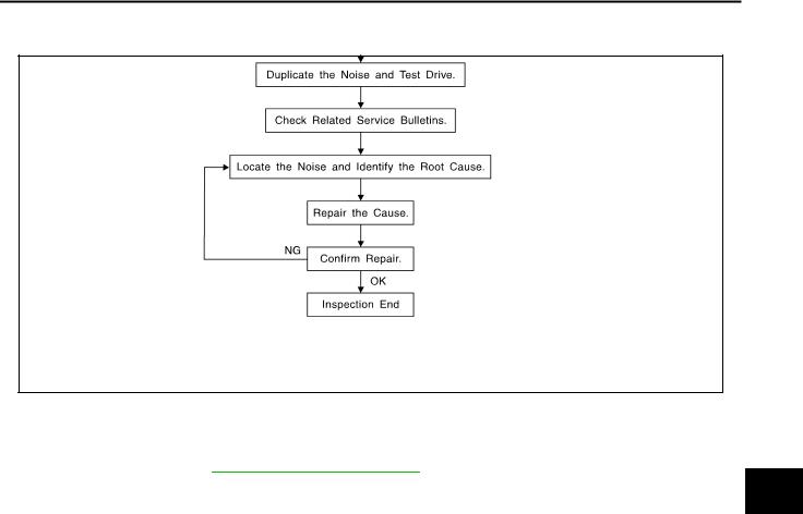
Work Flow
PFP:00000
A
AIS00611
B
C
D
E
F
G
SBT842
CUSTOMER INTERVIEW
Interview the customer if possible, to determine the conditions that exist when the noise occurs. Use the Diagnostic Worksheet during the interview to document the facts and conditions when the noise occurs and any customer's comments; refer toGW-9, "Diagnostic Worksheet" . This information is necessary to duplicate the conditions that exist when the noise occurs.
●The customer may not be able to provide a detailed description or the location of the noise. Attempt to obtain all the facts and conditions that exist when the noise occurs (or does not occur).
●If there is more than one noise in the vehicle, be sure to diagnose and repair the noise that the customer
is concerned about. This can be accomplished by test driving the vehicle with the customer.
●After identifying the type of noise, isolate the noise in terms of its characteristics. The noise characteristics are provided so the customer, service adviser and technician are all speaking the same language when
defining the noise.
H
GW
J
K
●Squeak —(Like tennis shoes on a clean floor)
Squeak characteristics include the light contact/fast movement/brought on by road conditions/hard sur-
faces=higher pitch noise/softer surfaces=lower pitch noises/edge to surface=chirping |
L |
●Creak—(Like walking on an old wooden floor)
Creak characteristics include firm contact/slow movement/twisting with a rotational movement/pitch
dependent on materials/often brought on by activity. |
M |
●Rattle—(Like shaking a baby rattle)
Rattle characteristics include the fast repeated contact/vibration or similar movement/loose parts/missing clip or fastener/incorrect clearance.
●Knock —(Like a knock on a door)
Knock characteristics include hollow sounding/sometimes repeating/often brought on by driver action.
●Tick—(Like a clock second hand)
Tick characteristics include gentle contacting of light materials/loose components/can be caused by driver action or road conditions.
●Thump—(Heavy, muffled knock noise)
Thump characteristics include softer knock/dead sound often brought on by activity.
●Buzz—(Like a bumble bee)
Buzz characteristics include high frequency rattle/firm contact.
●Often the degree of acceptable noise level will vary depending upon the person. A noise that you may judge as acceptable may be very irritating to the customer.
●Weather conditions, especially humidity and temperature, may have a great effect on noise level.
Revision: 2005 March |
GW-5 |
2005 X-Trail |

SQUEAK AND RATTLE TROUBLE DIAGNOSES
DUPLICATE THE NOISE AND TEST DRIVE
If possible, drive the vehicle with the customer until the noise is duplicated. Note any additional information on the Diagnostic Worksheet regarding the conditions or location of the noise. This information can be used to duplicate the same conditions when you confirm the repair.
If the noise can be duplicated easily during the test drive, to help identify the source of the noise, try to duplicate the noise with the vehicle stopped by doing one or all of the following:
1)Close a door.
2)Tap or push/pull around the area where the noise appears to be coming from.
3)Rev the engine.
4)Use a floor jack to recreate vehicle “twist”.
5)At idle, apply engine load (electrical load, half-clutch on M/T models, drive position on A/T models).
6)Raise the vehicle on a hoist and hit a tire with a rubber hammer.
●Drive the vehicle and attempt to duplicate the conditions the customer states exist when the noise occurs.
●If it is difficult to duplicate the noise, drive the vehicle slowly on an undulating or rough road to stress the vehicle body.
CHECK RELATED SERVICE BULLETINS
After verifying the customer concern or symptom, check ASIST for Technical Service Bulletins (TSBs) related to that concern or symptom.
If a TSB relates to the symptom, follow the procedure to repair the noise.
LOCATE THE NOISE AND IDENTIFY THE ROOT CAUSE
1.Narrow down the noise to a general area. To help pinpoint the source of the noise, use a listening tool (Chassis Ear: J-39570, Engine Ear and mechanics stethoscope).
2.Narrow down the noise to a more specific area and identify the cause of the noise by:
●removing the components in the area that you suspect the noise is coming from.
Do not use too much force when removing clips and fasteners, otherwise clips and fastener can be broken or lost during the repair, resulting in the creation of new noise.
●tapping or pushing/pulling the component that you suspect is causing the noise.
Do not tap or push/pull the component with excessive force, otherwise the noise will be eliminated only temporarily.
●feeling for a vibration with your hand by touching the component(s) that you suspect is (are) causing the noise.
●placing a piece of paper between components that you suspect are causing the noise.
●looking for loose components and contact marks.
Refer to GW-7, "Generic Squeak and Rattle Troubleshooting" .
REPAIR THE CAUSE
●If the cause is a loose component, tighten the component securely.
●If the cause is insufficient clearance between components:
–separate components by repositioning or loosening and retightening the component, if possible.
–insulate components with a suitable insulator such as urethane pads, foam blocks, felt cloth tape or urethane tape. A Nissan Squeak and Rattle Kit (J-43980) is available through your authorized Nissan Parts Department.
CAUTION:
Do not use excessive force as many components are constructed of plastic and may be damaged.
NOTE:
Always check with the Parts Department for the latest parts information.
The following materials are contained in the Nissan Squeak and Rattle Kit (J-43980). Each item can be ordered separately as needed.
URETHANE PADS [1.5 mm (0.059 in) thick] |
|
|
Insulates connectors, harness, etc. |
|
|
76268-9E005: 100 × 135 mm (3.94 × 5.31 in)/76884-71L01: 60 × 85 mm (2.36 × |
3.35 in)/76884- |
|
71L02: 15 × 25 mm (0.59 × |
0.98 in) |
|
INSULATOR (Foam blocks) |
|
|
Insulates components from contact. Can be used to fill space behind a panel. |
|
|
73982-9E000: 45 mm (1.77 |
in) thick, 50 × 50 mm (1.97 × 1.97 in)/73982- |
|
50Y00: 10 mm (0.39 in) thick, 50 × 50 mm (1.97 × 1.97 in) |
|
|
Revision: 2005 March |
GW-6 |
2005 X-Trail |

SQUEAK AND RATTLE TROUBLE DIAGNOSES
INSULATOR (Light foam block)
80845-71L00: 30 mm (1.18 in) thick, 30 × 50 mm (1.18 × 1.97 in) FELT CLOTHTAPE
Used to insulate where movement does not occur. Ideal for instrument panel applications. 68370-4B000: 15 × 25 mm (0.59 × 0.98 in) pad/68239-13E00: 5 mm (0.20 in) wide tape roll The following materials, not found in the kit, can also be used to repair squeaks and rattles. UHMW (TEFLON) TAPE
Insulates where slight movement is present. Ideal for instrument panel applications. SILICONE GREASE
Used in place of UHMW tape that will be visible or not fit. Will only last a few months. SILICONE SPRAY
Use when grease cannot be applied. DUCT TAPE
Use to eliminate movement.
CONFIRM THE REPAIR
Confirm that the cause of a noise is repaired by test driving the vehicle. Operate the vehicle under the same conditions as when the noise originally occurred. Refer to the notes on the Diagnostic Worksheet.
Generic Squeak and Rattle Troubleshooting |
AIS00612 |
Refer to Table of Contents for specific component removal and installation information.
INSTRUMENT PANEL
Most incidents are caused by contact and movement between:
1.The cluster lid A and instrument panel
2.Acrylic lens and combination meter housing
3.Instrument panel to front pillar garnish
4.Instrument panel to windshield
5.Instrument panel mounting pins
6.Wiring harnesses behind the combination meter
7.A/C defroster duct and duct joint
These incidents can usually be located by tapping or moving the components to duplicate the noise or by pressing on the components while driving to stop the noise. Most of these incidents can be repaired by applying felt cloth tape or silicon spray (in hard to reach areas). Urethane pads can be used to insulate wiring harness.
CAUTION:
Do not use silicone spray to isolate a squeak or rattle. If you saturate the area with silicone, you will not be able to recheck the repair.
CENTER CONSOLE
Components to pay attention to include:
1.Shifter assembly cover to finisher
2.A/C control unit and cluster lid C
3.Wiring harnesses behind audio and A/C control unit
The instrument panel repair and isolation procedures also apply to the center console.
DOORS
Pay attention to the:
1.Finisher and inner panel making a slapping noise
2.Inside handle escutcheon to door finisher
3.Wiring harnesses tapping
4.Door striker out of alignment causing a popping noise on starts and stops
Tapping or moving the components or pressing on them while driving to duplicate the conditions can isolate many of these incidents. You can usually insulate the areas with felt cloth tape or insulator foam blocks from the Nissan Squeak and Rattle Kit (J-43980) to repair the noise.
A
B
C
D
E
F
G
H
GW
J
K
L
M
Revision: 2005 March |
GW-7 |
2005 X-Trail |

SQUEAK AND RATTLE TROUBLE DIAGNOSES
TRUNK
Trunk noises are often caused by a loose jack or loose items put into the trunk by the owner. In addition look for:
1.Trunk lid dumpers out of adjustment
2.Trunk lid striker out of adjustment
3.The trunk lid torsion bars knocking together
4.A loose license plate or bracket
Most of these incidents can be repaired by adjusting, securing or insulating the item(s) or component(s) causing the noise.
SUNROOF/HEADLINING
Noises in the sunroof/headlining area can often be traced to one of the following:
1.Sunroof lid, rail, linkage or seals making a rattle or light knocking noise
2.Sunvisor shaft shaking in the holder
3.Front or rear windshield touching headlining and squeaking
Again, pressing on the components to stop the noise while duplicating the conditions can isolate most of these incidents. Repairs usually consist of insulating with felt cloth tape.
SEATS
When isolating seat noise it's important to note the position the seat is in and the load placed on the seat when the noise is present. These conditions should be duplicated when verifying and isolating the cause of the noise.
Cause of seat noise include:
1.Headrest rods and holder
2.A squeak between the seat pad cushion and frame
3.The rear seatback lock and bracket
These noises can be isolated by moving or pressing on the suspected components while duplicating the conditions under which the noise occurs. Most of these incidents can be repaired by repositioning the component or applying urethane tape to the contact area.
UNDERHOOD
Some interior noise may be caused by components under the hood or on the engine wall. The noise is then transmitted into the passenger compartment.
Causes of transmitted underhood noise include:
1.Any component mounted to the engine wall
2.Components that pass through the engine wall
3.Engine wall mounts and connectors
4.Loose radiator mounting pins
5.Hood bumpers out of adjustment
6.Hood striker out of adjustment
These noises can be difficult to isolate since they cannot be reached from the interior of the vehicle. The best method is to secure, move or insulate one component at a time and test drive the vehicle. Also, engine RPM or load can be changed to isolate the noise. Repairs can usually be made by moving, adjusting, securing, or insulating the component causing the noise.
Revision: 2005 March |
GW-8 |
2005 X-Trail |

SQUEAK AND RATTLE TROUBLE DIAGNOSES
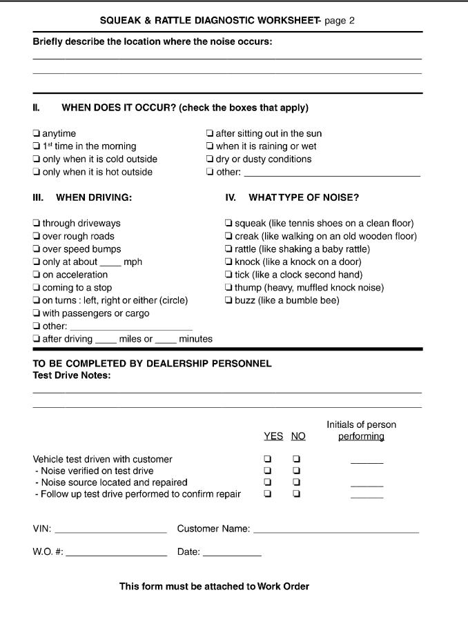
Diagnostic Worksheet
AIS00613
A
B
C
D
E
F
G
H
GW
J
K
L
M
PIIB0723E
Revision: 2005 March |
GW-9 |
2005 X-Trail |
SQUEAK AND RATTLE TROUBLE DIAGNOSES
SBT844
Revision: 2005 March |
GW-10 |
2005 X-Trail |
WINDSHIELD GLASS AND MOLDING
WINDSHIELD GLASS AND MOLDING
Removal and Installation
PFP:72700
A
AIS005Q7
B
C
D
E
F
G
PIIB1640E
1. |
Windshield molding |
2. Windshield glass |
3. Open cell foam dam |
4. |
Spacer |
|
H |
REMOVAL
1.Remove the front pillar garnish and the headlining. Refer to EI-36, "BODY SIDE TRIM" and EI-40,
"HEADLINING" .
2.Partially remove the roof rail. Refer to EI-28, "ROOF RAIL" .
3.Remove the cowl top cover. Refer to EI-19, "COWL TOP" .
4.Apply a protective tape around the windshield glass to protect the painted surface from damage.
5.Cut the windshield molding with a cutting knife.
After removing moldings using pliers, remove glass using piano wire or power cutting tool and an inflatable pump bag.
●If a windshield glass is to be reused, mark the body and the glass with mating marks.
WARNING:
When cutting the glass from the vehicle, always wear safety glasses and heavy gloves to help prevent glass splinters from entering your eyes or cutting your hands.
CAUTION:
●When a windshield glass is to be reused, do not use a cutting knife or power cutting tool.
●Be careful not to scratch the glass when removing.
●Do not set or stand the glass on its edge. Small chips may develop into cracks.
GW
J
K
L
M
PIIA0186E
Revision: 2005 March |
GW-11 |
2005 X-Trail |

WINDSHIELD GLASS AND MOLDING
INSTALLATION
●Use a genuine Nissan Urethane Adhesive Kit or equivalent and follow the instructions furnished with it.
●While the urethane adhesive is curing, open a door window. This will prevent the glass from being forced out by passenger compartment air pressure when a door is closed.
●The molding must be installed securely so that it is in position and leaves no gap.
●Inform the customer that the vehicle should remain stationary until the urethane adhesive has completely cured (preferably 24 hours). Curing time varies with temperature and humidity.
WARNING:
●Keep heat and open flames away as primers and adhesive are flammable.
●The materials contained in the kit are harmful if swallowed, and may irritate skin and eyes. Avoid contact with the skin and eyes.
●Use in an open, well ventilated location. Avoid breathing the vapors. They can be harmful if inhaled. If affected by vapor inhalation, immediately move to an area with fresh air.
●Driving the vehicle before the urethane adhesive has completely cured may affect the performance of the windshield in case of an accident.
CAUTION:
●Do not use an adhesive which is past its usable term. Shelf life of this product is limited to six months after the date of manufacture. Carefully adhere to the expiration or manufacture date printed on the box.
●Keep primers and adhesive in a cool, dry place. Ideally, they should be stored in a refrigerator.
●Do not leave primers or adhesive cartridge unattended with their caps open or off.
●The vehicle should not be driven for at least 24 hours or until the urethane adhesive has completely cured. Curing time varies depending on temperature and humidity. The curing time will increase under lower temperature and lower humidity.
PIIB1641E
Repairing Water Leaks
Leaks can be repaired without removing and reinstalling glass.
If water is leaking between the urethane adhesive material and body or glass, determine the extent of leakage. This can be done by applying water to the windshield area while pushing glass outward.
To stop the leak, apply primer (if necessary) and then urethane adhesive to the leak point.
Revision: 2005 March |
GW-12 |
2005 X-Trail |
SIDE WINDOW GLASS
SIDE WINDOW GLASS
Removal and Installation
PFP:83300
A
AIS005Q8
B
C
D
E
F
G
SIIA0168E
REMOVAL
1. Remove luggage side lower finisher and rear pillar finisher. Refer to EI-36, "BODY SIDE TRIM" .
2. Apply protective tape on body panels around side window glass to protect painted surfaces from damage.
● Remove glass using piano wire or power cutting tool and an inflatable pump bag.
● If a side window glass is to be reused, mark the body and the glass with mating marks.
WARNING:
When cutting the glass from the vehicle, always wear safety glasses and heavy gloves to help prevent glass splinters from entering your eyes or cutting your hands.
CAUTION:
● Be careful not to scratch the glass when removing.
SBF034B
● Do not set or stand the glass on its edge. Small chips may develop into cracks.
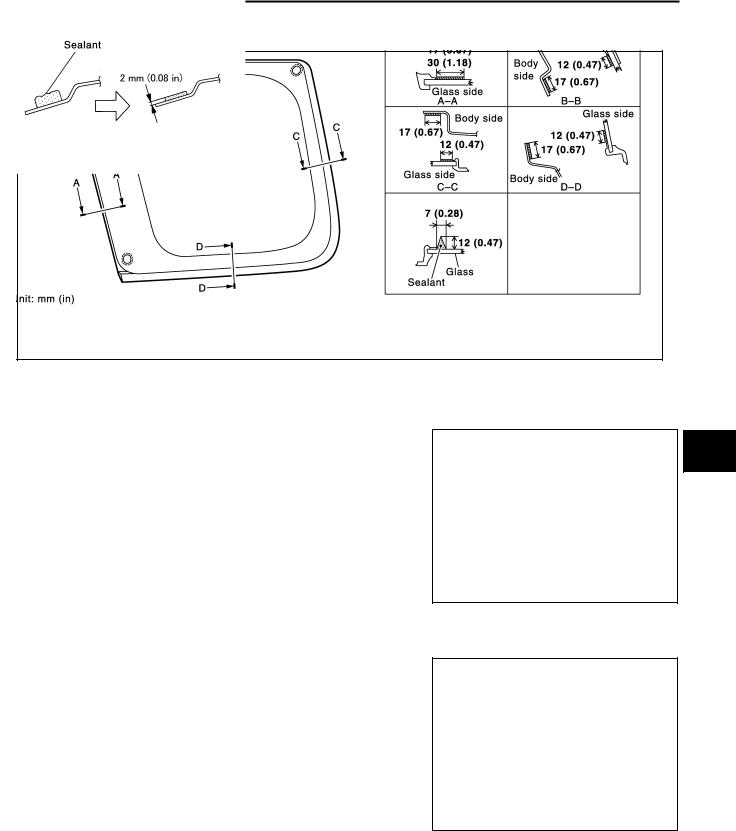
INSTALLATION
●With a knife, scrape off remaining adhesive left around on the side of vehicle body to as thin and flat as 2 mm (0.08 in).
SIIA1097E
●Use a genuine Nissan Urethane Adhesive Kit or equivalent and follow the instructions furnished with it.
●While the urethane adhesive is curing, open a door window. This will prevent the glass from being forced out by passenger compartment air pressure when a door is closed.
●The molding must be installed securely so that it is in position and leaves no gap.
●Inform the customer that the vehicle should remain stationary unit the urethane adhesive has completely cured (preferably 24 hours). Curing time varies with temperature and humidity.
H
GW
J
K
L
M
Revision: 2005 March |
GW-13 |
2005 X-Trail |

SIDE WINDOW GLASS
WARNING:
●Keep heat and open flames away as primers and adhesive are flammable.
●The materials contained in the Kit are harmful if swallowed, and may irritate skin and eyes. Avoid contact with the skin and eyes.
●Use in an open, well ventilated location. Avoid breathing the vapors. They can be harmful if inhaled. if affected by vapor inhalation, immediately move to an area with fresh air.
●Driving the vehicle before the urethane adhesive has completely cured may affect the performance of the side window in case of an accident.
CAUTION:
●Do not use an adhesive which is past its usable term. Shelf life of this product is limited to six months after the date of manufacture. Carefully adhere to the expiration or manufacture date printed on the box.
●Keep primers and adhesive in a cool, dry place. Ideally, they should be stored in a refrigerator.
●Do not leave primers or adhesive cartridge unattended with their caps open or off.
●The vehicle should not be driven for at least 24 hours or until the urethane adhesive has completely cured. Curing time varies depending on temperature and humidity. The curing time will increase under lower temperature and lower humidity.
REPAIRING WATER LEAKS
Leaks can be repaired without removing and reinstalling glass.
If water is leaking between the urethane adhesive material and body or glass, determine the extent of leakage. This can be done by applying water to the side window area while pushing glass outward.
To stop the leak, apply primer (if necessary) and then urethane adhesive to the leak point.
Revision: 2005 March |
GW-14 |
2005 X-Trail |

BACK DOOR WINDOW GLASS
BACK DOOR WINDOW GLASS
Removal and Installation
PFP:90300
A
AIS005Q9
B
C
D
E
F
G
H
GW
PIIB0582E
REMOVAL |
J |
1.Remove rear wiper arm. Refer to WW-14, "Removal and Installation of Rear Wiper Arms, Adjustment for Wiper Arms Stop Location" .
2.Remove rear washer nozzle. Refer to WW-16, "Removal and Installation of Rear Washer Nozzle" .
3.Remove rear window defogger connectors.
4.Remove high-mounted stop lamp. Refer to LT-27, "Removal and Installation of High-Mounted Stop Lamp"
5.Apply a protective tape around the back door window glass to prevent the painted surface from being damaged.
6.Cut adhesive using piano wire or power cutting tool and an inflatable pump bag.
●If a back door window glass is to be reused, mark the body and the glass with matching marks.
WARNING:
When cutting the glass from the vehicle, always wear safety glasses and heavy gloves to help prevent glass splinters from entering your eyes or cutting your hands.
CAUTION:
●When a back door window glass is to be reused, do not use a cutting knife or power cutting tool.
●Be careful not to scratch the glass when removing.
K
L
M
Revision: 2005 March |
GW-15 |
2005 X-Trail |
BACK DOOR WINDOW GLASS
●Do not set or stand the glass on its edge. Small chips may develop into cracks.
PIIB0415E
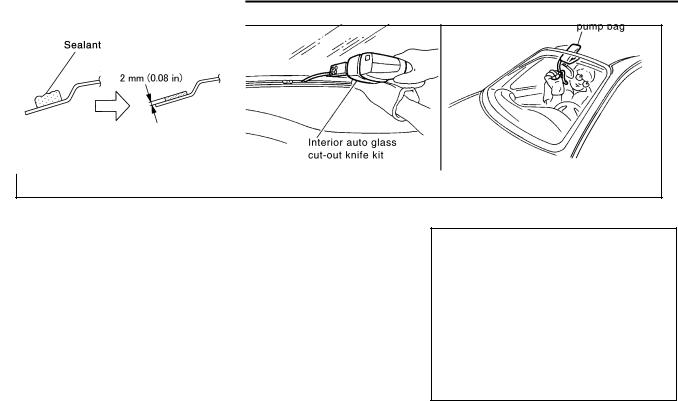
INSTALLATION
●With a knife, scrape off remaining adhesive left around on the side of vehicle body to as thin and flat as 2 mm (0.08 in).
●Use a genuine Nissan Urethane Adhesive Kit or equivalent and follow the instructions furnished with it.
●While the urethane adhesive is curing, open a door window. This will prevent the glass from being forced out by passenger compartment air pressure when a door is closed.
●Inform the customer that the vehicle should remain stationary until the urethane adhesive has completely cured (preferably 24 hours). Curing time varies with temperature and humidity.
SIIA1097E
WARNING:
●Keep heat and open flames away as primers and adhesive are flammable.
●The materials contained in the kit are harmful if swallowed, and may irritate skin and eyes. Avoid contact with the skin and eyes.
●Use in an open, well ventilated location. Avoid breathing the vapors. They can be harmful if inhaled. If affected by vapor inhalation, immediately move to an area with fresh air.
●Driving the vehicle before the urethane adhesive has completely cured may affect the performance of the back door window in case of an accident.
CAUTION:
●Do not use an adhesive which is past its usable term. Shelf life of this product is limited to six months after the date of manufacture. Carefully adhere to the expiration or manufacture date printed on the box.
●Keep primers and adhesive in a cool, dry place. Ideally, they should be stored in a refrigerator.
●Do not leave primers or adhesive cartridge unattended with their caps open or off.
●The vehicle should not be driven for at least 24 hours or until the urethane adhesive has completely cured. Curing time varies depending on temperature and humidity. The curing time will increase under lower temperature and lower humidity.
Revision: 2005 March |
GW-16 |
2005 X-Trail |
REAR WINDOW DEFOGGER
REAR WINDOW DEFOGGER |
PFP:25350 |
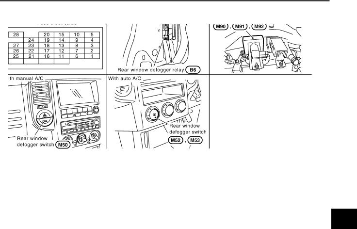
Component Parts and Harness Connector Location |
AIS005QA |
|
|
PIIB1607E |
|
System Description |
AIS0062J |
||
The rear window defogger system is controlled by smart entrance control unit.The rear window defogger operates only for approximately 15 minutes.
Power is supplied at all times
●through 20A fuse [No.25, located in the fuse block (J/B)]
●to rear window defogger relay terminal 3
●through 10A fuse [No.27, located in the fuse block (J/B)]
●to rear window defogger relay terminal 6 (with door mirror defogger)
●through 10A fuse [No.26, located in the fuse block (J/B)]
●to smart entrance control unit terminal 49
With the ignition switch in the ON or START position,
Power is supplied
●through 10A fuse [No.5, located in the fuse block (J/B)]
●to rear window defogger relay terminal 1 and
●to smart entrance control unit terminal 27.
Ground is supplied
●to smart entrance control unit terminals 43 and 64
●through body ground M27 and M70.
●to rear window defogger switch terminals 2 and 4 (with manual A/C) or
●to A/C auto amp. terminal 3 (with auto A/C)
●through body ground M27 and M70.
When the rear window defogger switch is turned ON,
Ground is supplied
●to smart entrance control unit terminal 14
●through rear window defogger switch 1 (with manual A/C) or
●through A/C auto amp. terminal 22 (with auto A/C)
Terminal 37 of the smart entrance control unit then supplies ground to the rear window defogger relay terminal 2.
With power and ground supplied, the rear window defogger relay is energized. Power is supplied
●through rear window defogger relay terminal 5 and 7
Revision: 2005 March |
GW-17 |
2005 X-Trail |
A
B
C
D
E
F
G
H
GW
J
K
L
M

REAR WINDOW DEFOGGER
●to the rear window defogger and door mirror defogger.
The rear window defogger has an independent ground.
With power and ground supplied, the rear window defogger filaments heat and defog the rear window.
When the system is activated, the rear window defogger indicator illuminates in the rear window defogger switch.
Power is supplied
●through rear window defogger relay terminal 5
●to rear window defogger switch terminal 3 (with manual A/C) or
●to A/C auto amp. terminal 23 (with auto A/C).
Revision: 2005 March |
GW-18 |
2005 X-Trail |

REAR WINDOW DEFOGGER
Wiring Diagram — DEF —
AIS005QD
A
B
C
D
E
F
G
H
GW
J
K
L
M
TIWB0066E
Revision: 2005 March |
GW-19 |
2005 X-Trail |

REAR WINDOW DEFOGGER
TIWB0067E
Revision: 2005 March |
GW-20 |
2005 X-Trail |
REAR WINDOW DEFOGGER
Terminals and Reference Value for Smart Entrance Control Unit |
AIS005QF |
|||||||
|
|
|
|
|
|
|
|
|
TERMINAL |
WIRE |
ITEM |
CONDITION |
VOLTAGE (V) |
||||
COLOR |
(Approx.) |
|||||||
|
|
|
|
|
||||
|
|
|
|
|
|
|
|
|
14 |
LG/B |
Rear window defogger switch signal |
Rear window |
|
: ON |
0 |
|
|
|
|
|
|
|||||
defogger switch |
|
|
|
|
||||
|
: OFF |
Battery voltage |
||||||
|
|
|
|
|||||
|
|
|
|
|
||||
|
|
|
|
|
|
|
|
|
27 |
G |
Ignition switch ON |
Ignition switch position |
|
Battery voltage |
|||
(ON or START) |
|
|||||||
|
|
|
|
|
|
|||
|
|
|
|
|
|
|
|
|
37 |
G/W |
Rear window defogger relay control signal |
Rear window |
|
: ON |
0 |
|
|
|
|
|
|
|||||
defogger switch |
|
|
|
|
||||
|
: OFF |
Battery voltage |
||||||
|
|
|
|
|||||
|
|
|
|
|
||||
|
|
|
|
|
|
|
|
|
43 |
B |
Ground |
— |
|
0 |
|
||
|
|
|
|
|
|
|
||
49 |
L/R |
Power source (Fuse) |
— |
|
Battery voltage |
|||
|
|
|
|
|
|
|
||
64 |
B |
Ground |
— |
|
0 |
|
||
|
|
|
|
|
|
|
|
|
Work Flow |
|
|
|
|
AIS0062Q |
|||
1.Check the symptom and customer's requests.
2.Understand the outline of system. Refer to GW-17, "System Description"
3.According to the trouble diagnosis chart, repair or replace the cause of the malfunction. Refer to GW-21,
"Trouble Diagnoses"
4.Does rear window defogger operate normally? YES: GO TO 5, NO: GO TO 3.
5.INSPECTION END.
Trouble Diagnoses |
AIS0062K |
A
B
C
D
E
F
G
H
●Make sure that other systems using the signal of the following systems operate normally.
|
Symptom |
|
Diagnoses / Service procedure |
Refer to page |
|
|
|
|
|
|
|
|
|
1. |
Check rear window defogger relay power supply |
GW-21 |
|
|
|
|
|
|
|
|
Rear window defogger and door mirror defogger |
2. |
Check smart entrance control unit power supply and |
GW-23 |
|
|
does not operate. |
ground |
|||
|
|
|
|
||
|
|
|
|
|
|
|
|
3. |
Check rear window defogger switch circuit |
GW-24 |
|
|
|
|
|
|
|
|
Rear window defogger alone does not operate. |
1. |
Check rear window defogger circuit |
GW-26 |
|
|
|
|
|
|
|
|
Door mirror defogger alone does not operate. |
1. |
Check door mirror defogger circuit |
GW-27 |
|
|
|
|
|
|
|
|
Rear window defogger switch does not light, but |
1. |
Check rear window defogger indicator lamp circuit |
GW-29 |
|
|
rear window defogger operates. |
||||
|
|
|
|
|
|
|
|
|
|
|
|
Check Rear Window Defogger Relay Power Supply |
AIS0062R |
||||
1. CHECK FUSE
●Check 10A fuse [No. 5, located in the fuse block (J/B)]
●Check 10A fuse [No. 27, located in the fuse block (J/B)]
●Check 20A fuse [No. 25, located in the fuse block (J/B)]
NOTE:
Refer to GW-17, "Component Parts and Harness Connector Location"
OK or NG
OK |
>> GO TO 2. |
NG |
>> If fuse is blown, be sure to eliminate cause of malfunction before installing new fuse. Refer to PG- |
|
2, "POWER SUPPLY ROUTING" |
GW
J
K
L
M
Revision: 2005 March |
GW-21 |
2005 X-Trail |
Loading...