


XTrail T30 2005
Table of contents
 Loading...
PG-1
POWER SUPPLY, GROUND & CIRCUIT ELE MENTS
K ELECTRICAL
CONTENTS
C
D
E
F
G
H
I
J
L
M
SECTION PG
A
B
PG
Revision: 2005 March 2005 X-Trail
POWER SUPPLY, GROUND & CIRCUIT ELEMENTS
POWER SUPPLY ROUTING ...................................... 2
Schematic ................................................................ 2
Wiring Diagram - POWER - ..................................... 3
BA TTERY POWER SUPP LY - I GNITION SW. I N
ANY POSITION ..................................................... 3
ACCESSORY POWER SUPPLY - IGNITION SW.
IN “ACC” OR “ON” ................................................ 7
IGNITION POWER SUPPLY - IGNITION SW. IN
“ON” AND/OR “START” ......................................... 8
Fuse ....................................................................... 12
Fusible Link ................................. ....... ...... ....... ....... 12
Circuit Breaker ....................................................... 12
GROUND .................................................................. 13
Ground Distribution ................................................ 13
MAIN HARNESS ................................................. 13
ENGINE ROOM HARNESS ................................ 15
ENGINE CONTROL HARNESS ......................... 17
BODY HARNESS ................................................ 18
BODY NO. 2 HARNESS ..................................... 19
BACK DOOR SUB HARNESS/REAR WINDOW
DEFOGGER HARNESS ..................................... 20
HARNESS ................................ .......................... ....... 21
Harness Layout ...................................................... 21
HOW TO READ HARNESS LAYOUTS ............... 21
OUTLINE ............................ ...... ....... .................... 22
MAIN HARNESS ................................................. 23
ENGINE ROOM HARNESS ................................ 25
ENGINE CONTROL HARNESS ......................... 30
BODY HARNESS ................................................32
BODY NO. 2 HARNESS ..................................... 33
ROOM LAMP HARNESS .................................... 34
FRONT DOOR HARNESS .................................. 35
REAR DOOR HARNESS .................................... 36
BACK DOOR HARNESS .................................... 37
Wiring Diagram Codes (Cell Codes) ...................... 38
ELECTRICAL UNITS LOCATION ............................ 41
Electrical Units Location ......................................... 41
ENGINE COMPARTMENT .................................. 41
PASSENGER COMPARTMENT .........................42
HARNESS CONNECTOR ........... ...... ....... ...... ....... ....44
Description ................... ...... ....... ...... ........................ 44
HARNESS CONNECTOR (TAB-LOCKING
TYPE) ............................. ..................................... 44
HARNESS CONNECTOR (SLIDE-LOCKING
TYPE) ............................. ..................................... 45
ELECTRICAL UNITS ................................................ 46
Terminal Arrangement ............................................ 46
STANDARDIZED RELAY .......................................... 47
Description ................... ...... ....... ...... ........................ 47
NORMAL OPEN, NORMAL CLOSED AND
MIXED TYPE RELAYS ........................................ 47
TYPE OF STANDARDIZED RELAYS .................47
FUSE BLOCK - JUNCTION BOX (J/B) .................... 49
Terminal Arrangement ............................................ 49
FUSE AND FUSIBLE LINK BOX .......................... ....50
Terminal Arrangement ............................................ 50
PG-2
POWER SUPPLY ROUTING
Revision: 2005 March 2005 X-Trail
POWER SUPPLY ROUTING PFP:00011
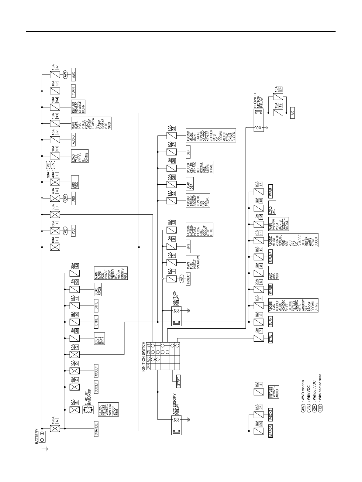
Schematic AKS00BER
TKWB0202E
POWER SUPPLY ROUTING
PG-3
C
D
E
F
G
H
I
J
L
M
A
B
PG
Revision: 2005 March 2005 X-Trail
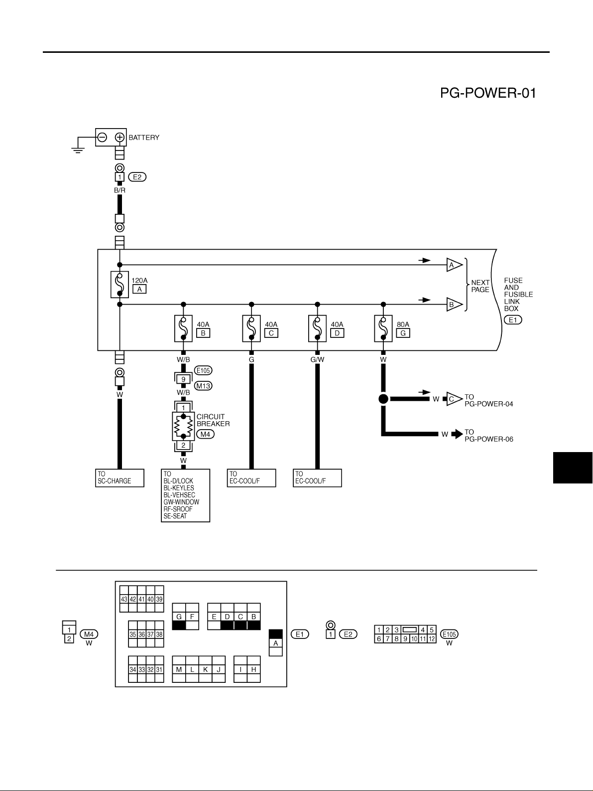
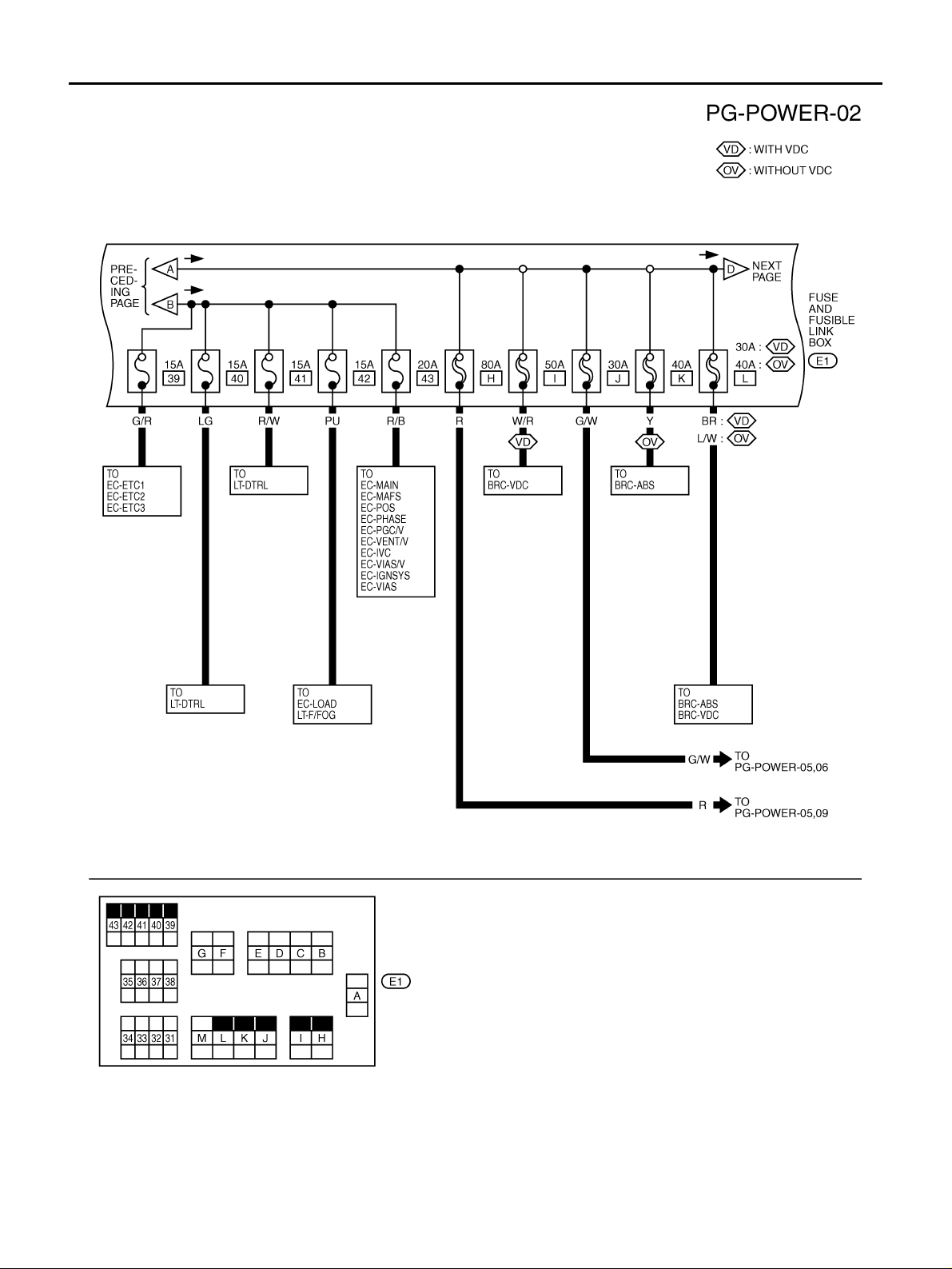
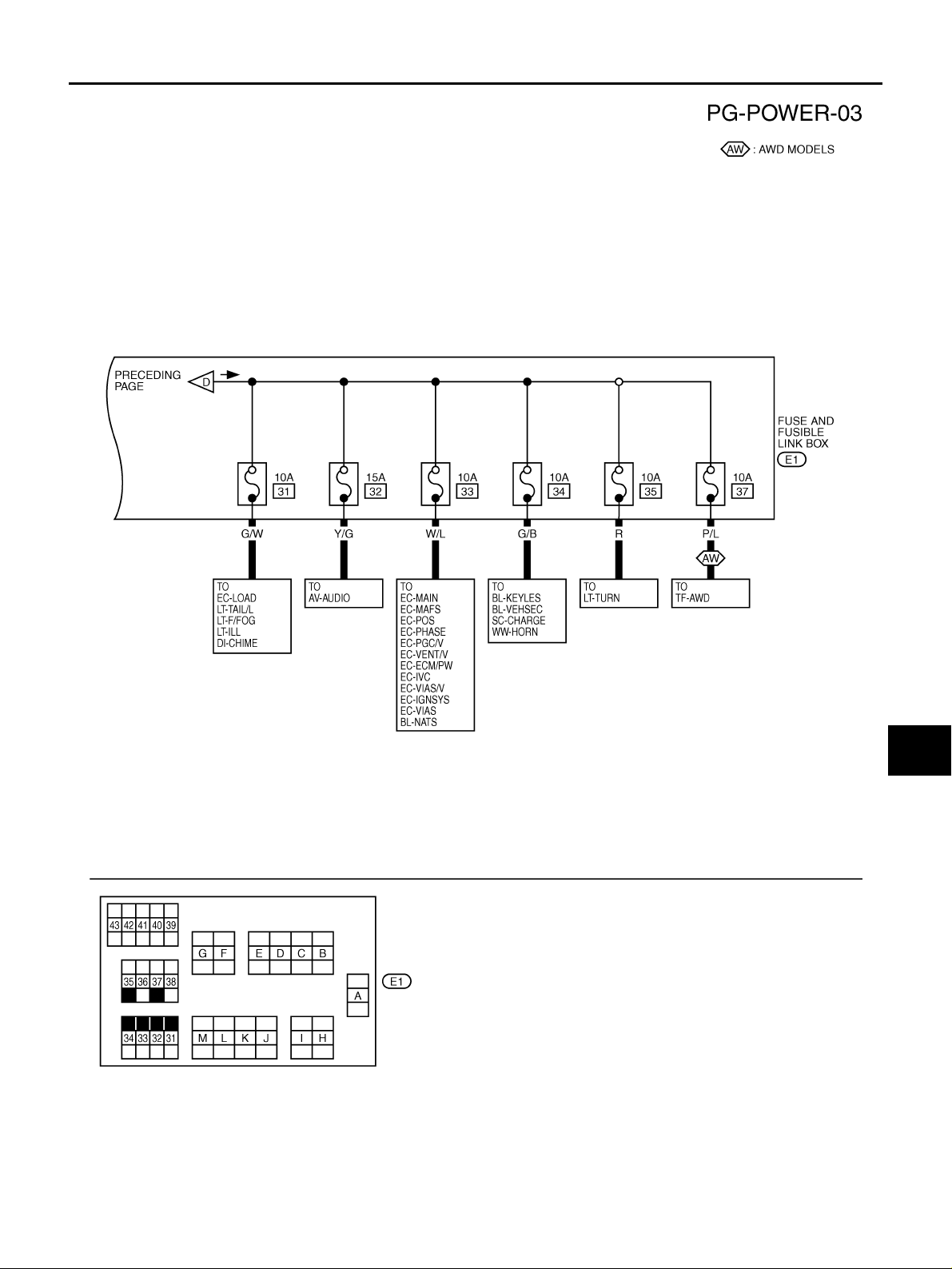
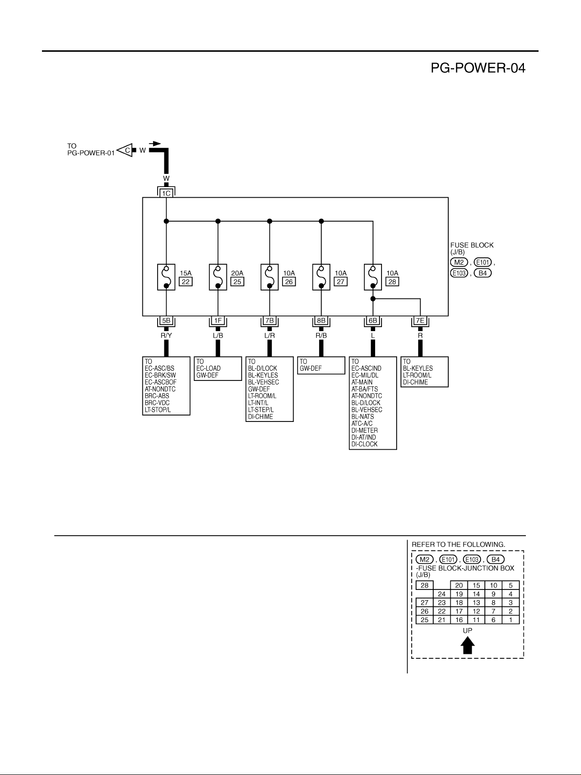
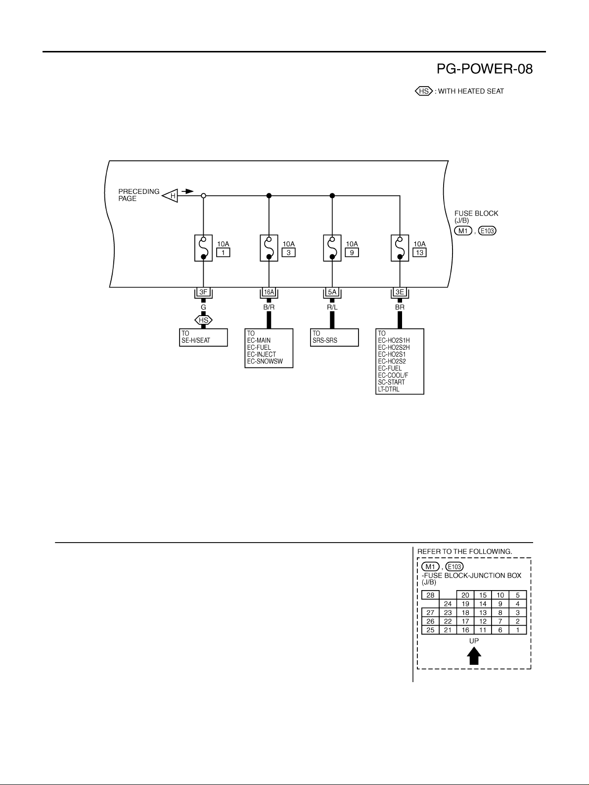
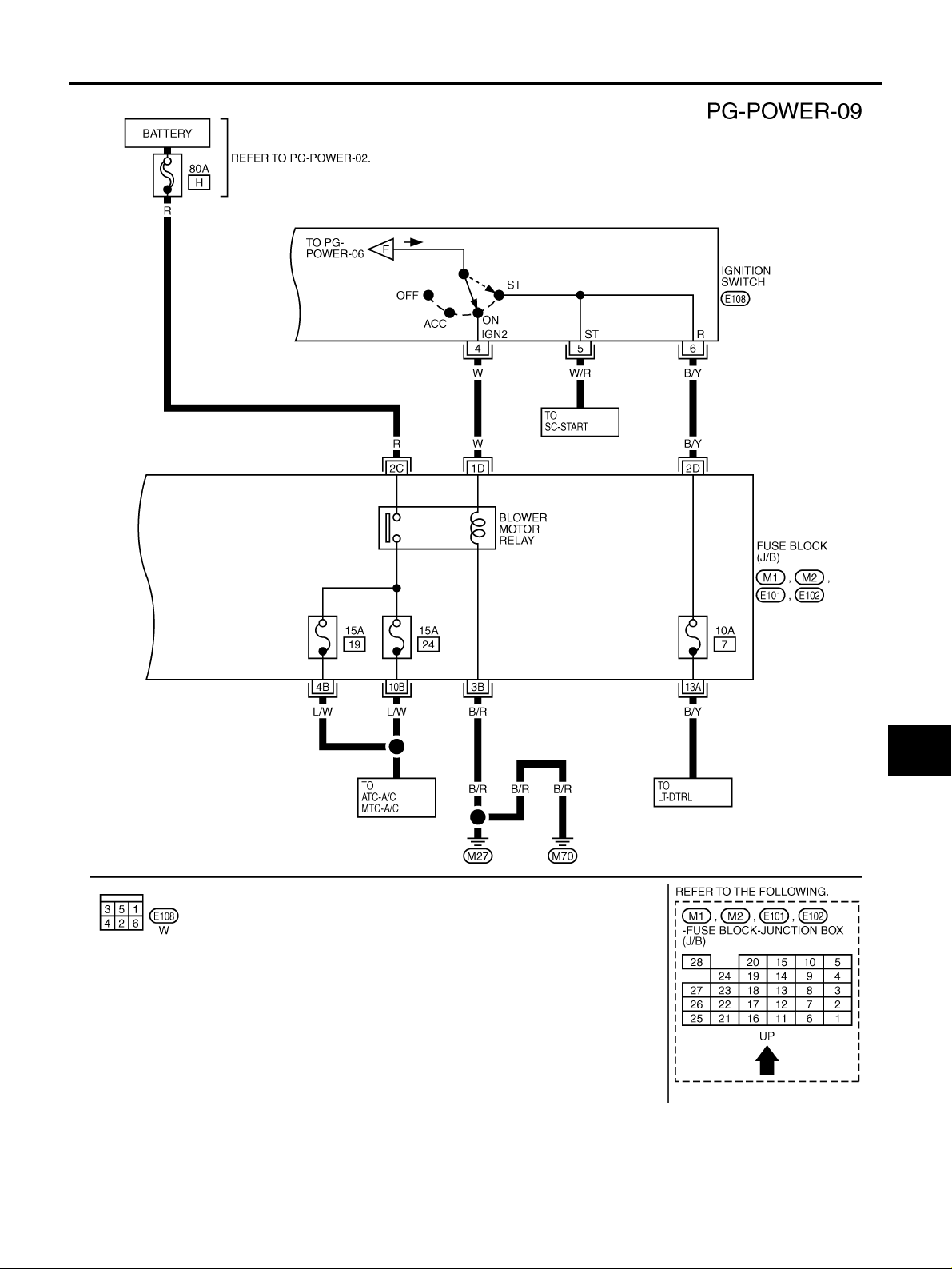
Wiring Diagram - POWER - AKS00BES
BATTERY POWER SUPPLY - IGNITION SW. IN ANY POSITION
TKWB0203E
PG-4
POWER SUPPLY ROUTING
Revision: 2005 March 2005 X-Trail
TKWB0204E
POWER SUPPLY ROUTING
PG-5
C
D
E
F
G
H
I
J
L
M
A
B
PG
Revision: 2005 March 2005 X-Trail
TKWB0205E
PG-6
POWER SUPPLY ROUTING
Revision: 2005 March 2005 X-Trail
TKWB0206E
POWER SUPPLY ROUTING
PG-7
C
D
E
F
G
H
I
J
L
M
A
B
PG
Revision: 2005 March 2005 X-Trail
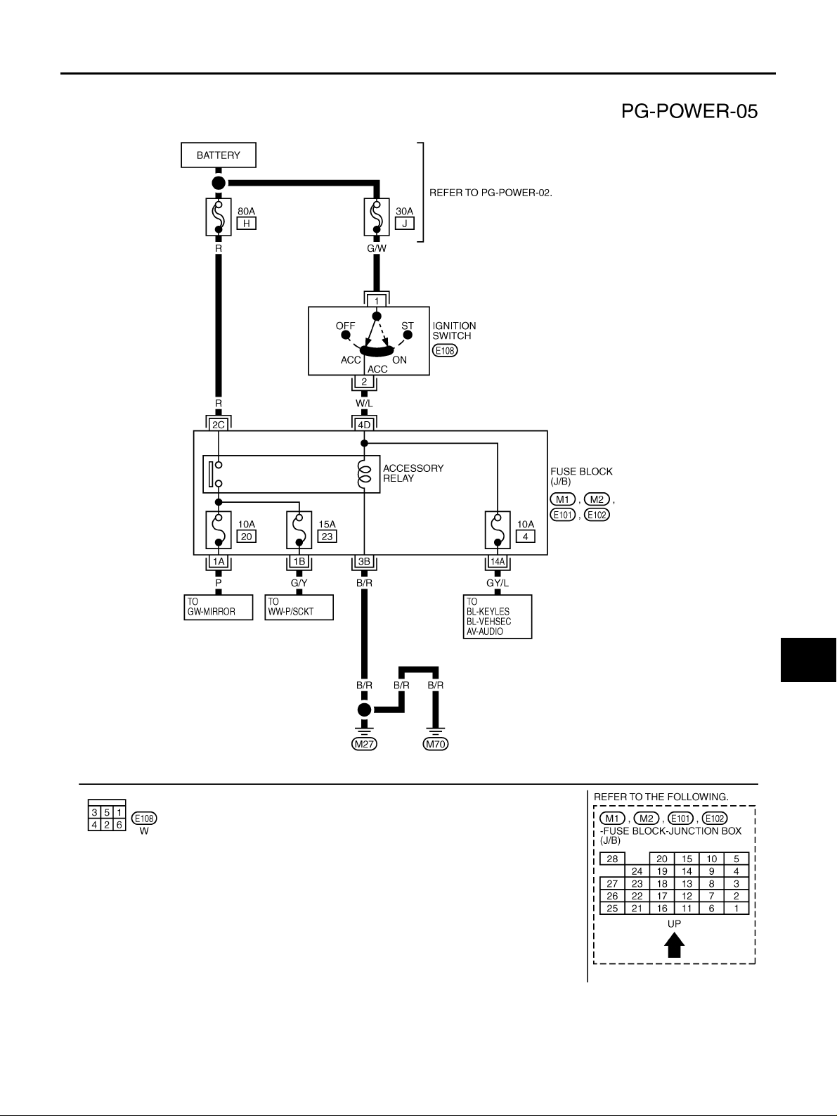
ACCESSORY POWER SUPPLY - IGNITION SW. IN “ACC” OR “ON”
TKWB0207E
PG-8
POWER SUPPLY ROUTING
Revision: 2005 March 2005 X-Trail
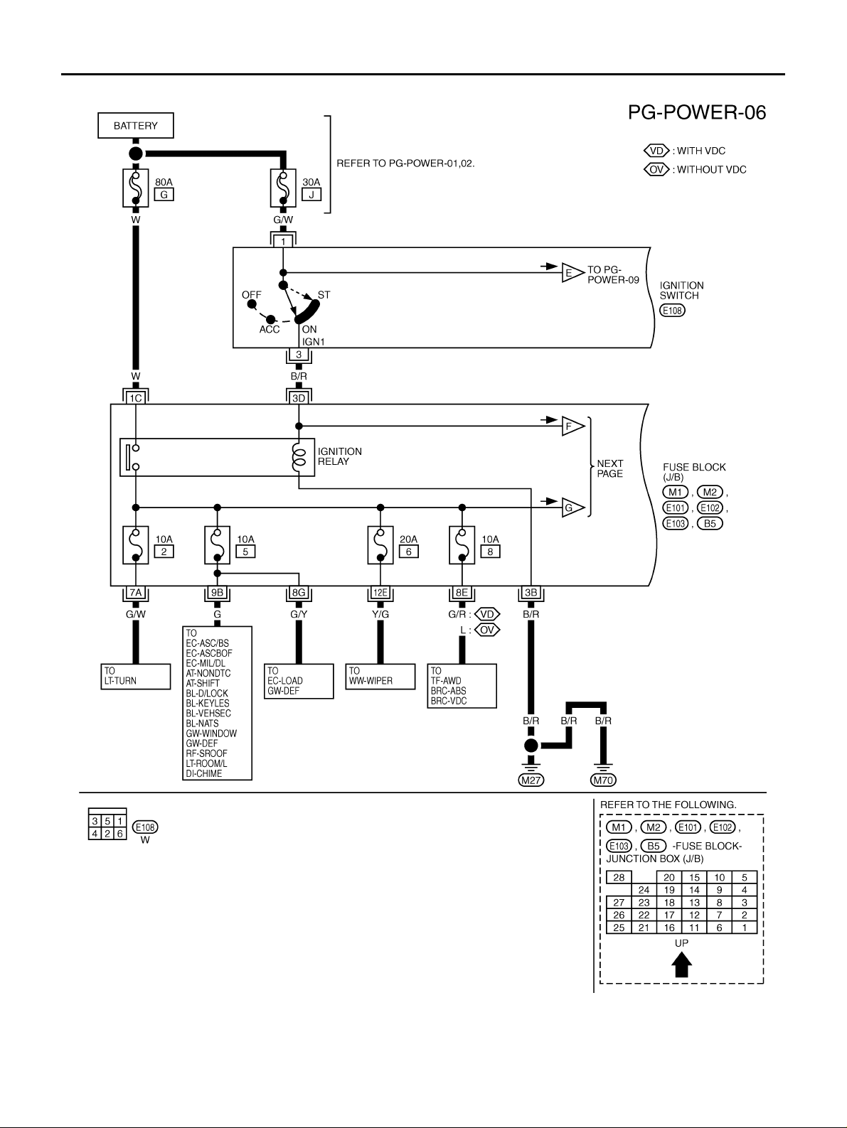
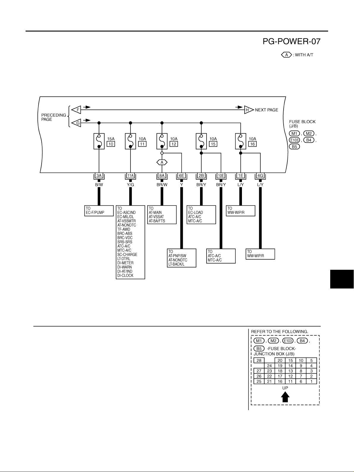
IGNITION POWER SUPPLY - IGNITION SW. IN “ON” AND/OR “START ”
TKWB0208E
POWER SUPPLY ROUTING
PG-9
C
D
E
F
G
H
I
J
L
M
A
B
PG
Revision: 2005 March 2005 X-Trail
TKWB0209E
PG-10
POWER SUPPLY ROUTING
Revision: 2005 March 2005 X-Trail
TKWB0210E
POWER SUPPLY ROUTING
PG-11
C
D
E
F
G
H
I
J
L
M
A
B
PG
Revision: 2005 March 2005 X-Trail
TKWB0211E
PG-12
POWER SUPPLY ROUTING
Revision: 2005 March 2005 X-Trail
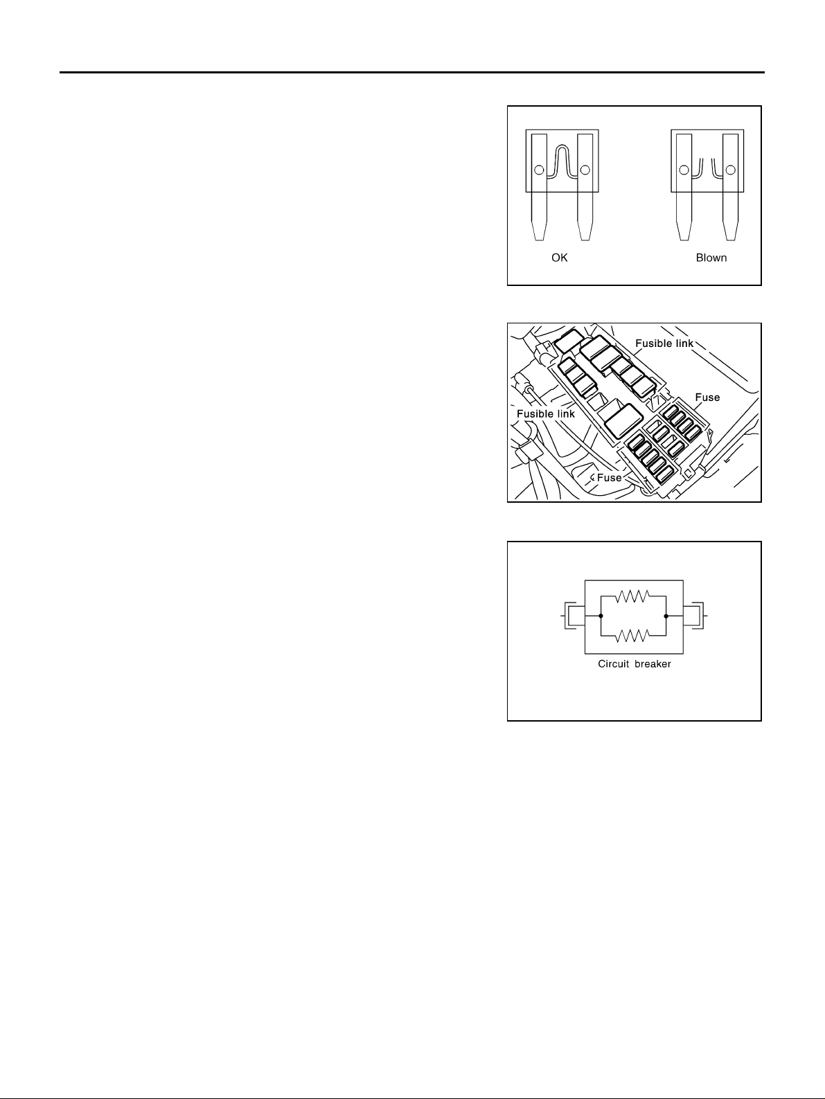
Fuse AKS00BET
● If fuse is bl own , be sure to el im ina te ca us e o f mal fu nc t io n bef or e
installing new fuse.
● Use fuse of specified rating. Never use fuse of more than speci-
fied rating.
● Do not partially install fuse; always insert it into fuse holder prop-
erly.
● Remove fuse for “ELECTRICAL PARTS (BAT)” if vehicle is not
used for a long period of time.
Fusible Link AKS00BEU
A melted fusible link can be detected either by visual inspection or by
feeling with finger tip. If its condition is questionable, use circuit
tester or test lamp.
CAUTION:
● If fusible link shou ld melt, it is possible tha t critical circuit
(power supply or l arge current carrying ci rcuit) is shorted.
In such a case, carefully check and elim inate ca use of ma l-
function.
● Never wrap outside of fusible link with vinyl tape. Important:
Never let fusible link tou ch any other wiring ha rness, vinyl
or rubber parts.
Circuit Breaker AKS00BEV
The PTC thermistor generates heat in response to current flow. The
temperature (and resistance) of the thermistor el ement varies with
current flow. Excessive current flow will cause the element's temper-
ature to rise. When the temperature reaches a specified level, the
electrical resistance will rise sharply to control the circuit current.
Reduced current flow will cause the element to cool. Resistance falls
accordingly and normal circuit current flow is allowed to resume.
CEL083
CKIB0025E
SEL109W
GROUND
PG-13
C
D
E
F
G
H
I
J
L
M
A
B
PG
Revision: 2005 March 2005 X-Trail
GROUND PFP:00011
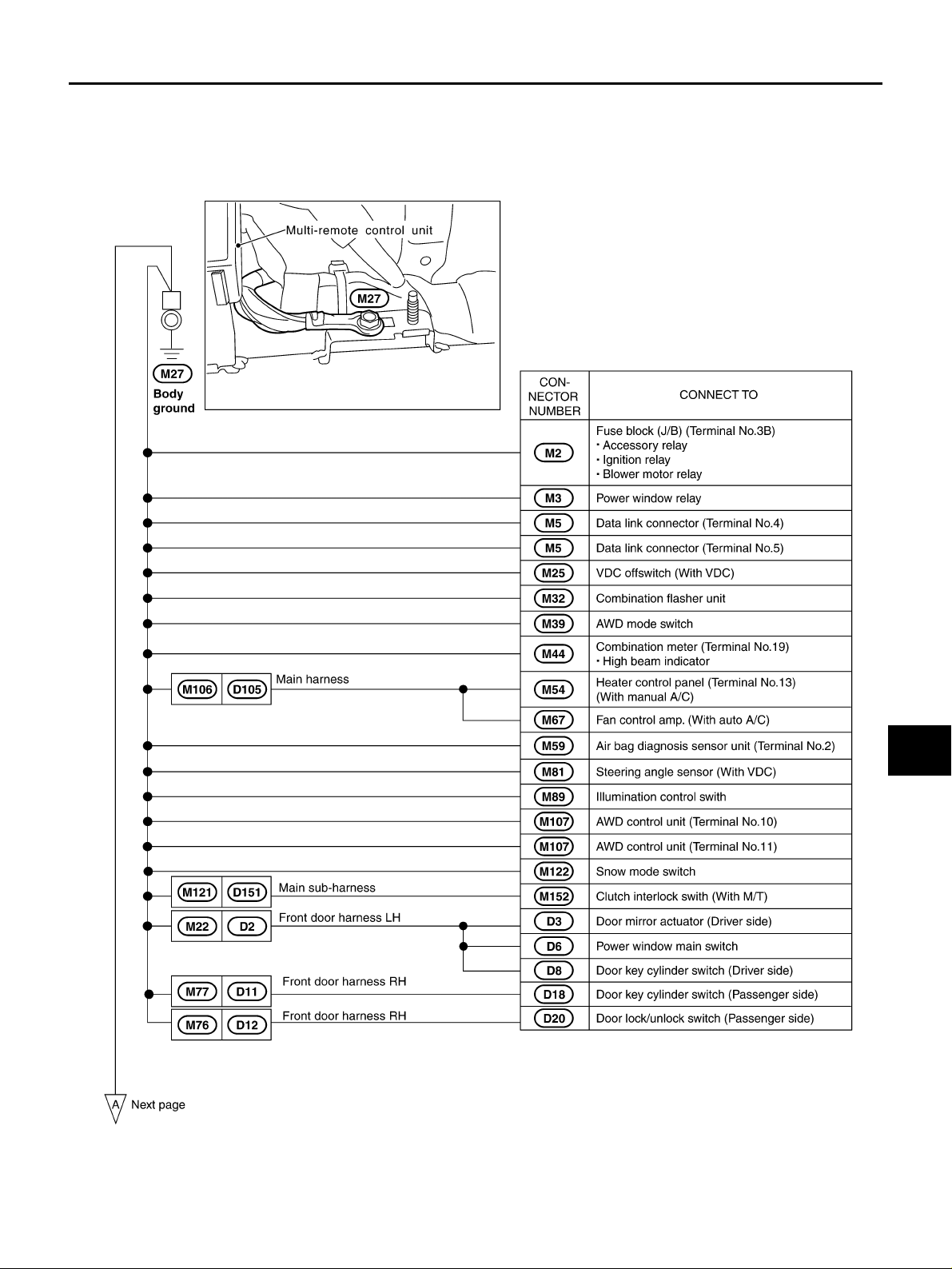
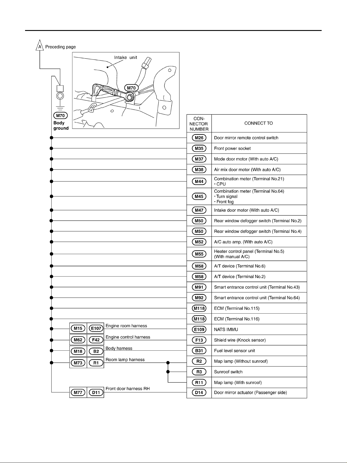
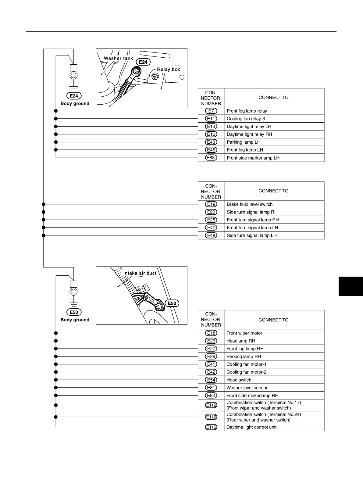
Ground Distribution AKS00BEW
MAIN HARNESS
CKIB0026E
PG-14
GROUND
Revision: 2005 March 2005 X-Trail
CKIB0027E
GROUND
PG-15
C
D
E
F
G
H
I
J
L
M
A
B
PG
Revision: 2005 March 2005 X-Trail
ENGINE ROOM HARNESS
CKIB0028E
Loading...