


 Loading...
F BRAKES
SECTION BRC
BRAKE CONTROL SYSTEM
A
B
C
D
CONTENTS
E
ABS |
|
PRECAUTIONS ......................................................... |
4 |
Precautions for Supplemental Restraint System |
|
(SRS) “AIR BAG” and “SEAT BELT PRE-TEN- |
|
SIONER” ................................................................. |
4 |
Precautions for Brake System ................................. |
4 |
Precautions for Brake Control ................................. |
4 |
PREPARATION .......................................................... |
5 |
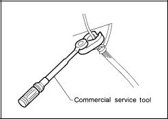
Commercial Service Tools ....................................... |
5 |
SYSTEM DESCRIPTION ........................................... |
6 |
System Diagram ...................................................... |
6 |
Functions ................................................................. |
6 |
ABS ...................................................................... |
6 |
EBD ...................................................................... |
6 |
Operation That Is Not “System Error” ................... |
6 |
ABS ...................................................................... |
6 |
Fail-Safe Function ................................................... |
6 |
ABS, EBD ............................................................. |
6 |
Hydraulic Circuit Diagram ....................................... |
7 |
CAN COMMUNICATION ........................................... |
8 |
System Description ................................................. |
8 |
TROUBLE DIAGNOSIS ............................................. |
9 |
How to Perform Trouble Diagnosis for Quick and |
|
Accurate Repair ...................................................... |
9 |
INTRODUCTION .................................................. |
9 |
DIAGNOSIS FLOW CHART .............................. |
10 |
ASKING COMPLAINTS ...................................... |
11 |
EXAMPLE OF DIAGNOSIS SHEET ................... |
11 |
Component Parts Location .................................... |
12 |
Schematic ............................................................. |
13 |
Wiring Diagram ..................................................... |
14 |
Control Unit Input/Output Signal Standard ............ |
18 |
REFERENCE VALUE FROM CONSULT-II ........ |
18 |
CONSULT-II Functions .......................................... |
19 |
CONSULT-II MAIN FUNCTION .......................... |
19 |
CONSULT-IIBASICOPERATIONPROCEDURE |
|
... 19 |
|
Self-Diagnosis ....................................................... |
19 |
OPERATION PROCEDURE .............................. |
19 |
ERASE MEMORY .............................................. |
20 |
DISPLAY ITEM LIST .......................................... |
20 |
Data Monitor .......................................................... |
21 |
OPERATION PROCEDURE ............................... |
21 |
DISPLAY ITEM LIST .......................................... |
22 |
Active Test ............................................................. |
23 |
OPERATION PROCEDURE ............................... |
23 |
SOLENOID VALVE ............................................. |
23 |
ABS MONITOR .................................................. |
24 |
For Fast and Accurate Diagnosis .......................... |
24 |
PRECAUTIONS FOR DIAGNOSIS .................... |
24 |
Basic Inspection .................................................... |
25 |
BASIC INSPECTION 1: BRAKE FLUID LEVEL, |
|
LEAKAGE AND BRAKE PAD ............................. |
25 |
BASIC INSPECTION 2: POWER SUPPLY CIR- |
|
CUIT TERMINAL LOOSENESS AND BATTERY... |
25 |
BASIC INSPECTION 3: INSPECTION OF ABS |
|
WARNING LAMP ............................................... |
25 |
Inspection 1: Wheel Sensor Circuit ........................ |
26 |
INSPECTION PROCEDURE ............................. |
26 |
Inspection 2: ABS Actuator and Electric Unit (Con- |
|
trol Unit) ................................................................. |
28 |
Inspection 3: ABS Actuator and Electric Unit (Con- |
|
trol Unit) Power Supply and Ground Circuit ........... |
28 |
Inspection 4: ABS Actuator Relay or ABS Motor |
|
Relay Power Circuit ............................................... |
29 |
Inspection 5: G Sensor Circuit (Only AWD Models)... |
30 |
Inspection 6: CAN Communication Circuit ............ |
32 |
Component Inspection ........................................... |
33 |
PARKING BRAKE SWITCH ............................... |
33 |
BRAKE FLUID LEVEL SWITCH ........................ |
33 |
Symptom 1: Excessive ABS Function Operation |
|
Frequency .............................................................. |
33 |
Symptom 2: Unexpected Pedal Reaction .............. |
34 |
Symptom 3: The Stopping Distance Is Long ......... |
34 |
Symptom 4: ABS Function Does Not Operate ...... |
35 |
Symptom 5: Pedal Vibration or ABS Operation |
|
Sound Occurs ........................................................ |
35 |
Symptom 6: ABS Warning Lamp Indication Is Not |
|
Normal ................................................................... |
35 |
Revision: 2005 March |
BRC-1 |
2005 X-Trail |
BRC
G
H
I
J
K
L
M

WHEEL SENSORS .................................................. |
36 |
Removal and Installation ....................................... |
36 |
COMPONENTS .................................................. |
36 |
REMOVAL .......................................................... |
36 |
INSTALLATION ................................................... |
36 |
SENSOR ROTOR ..................................................... |
37 |
Removal and Installation (2WD Model) ................. |
37 |
REMOVAL .......................................................... |
37 |
INSTALLATION ................................................... |
37 |
Removal and Installation (AWD Model) ................. |
37 |
REMOVAL .......................................................... |
37 |
INSTALLATION ................................................... |
37 |
ACTUATOR AND ELECTRIC UNIT (ASSEMBLY)... |
38 |
Removal and Installation ....................................... |
38 |
COMPONENTS .................................................. |
38 |
REMOVAL .......................................................... |
39 |
INSTALLATION ................................................... |
39 |
G SENSOR ............................................................... |
40 |
Removal and Installation (Only AWD Models) ....... |
40 |
REMOVAL .......................................................... |
40 |
INSTALLATION ................................................... |
40 |
VDC/TCS/ABS |
|
PRECAUTIONS ........................................................ |
41 |
Precautions for Supplemental Restraint System |
|
(SRS) “AIR BAG” and “SEAT BELT PRE-TEN- |
|
SIONER” ................................................................ |
41 |
Precautions for Brake System ............................... |
41 |
Precautions for Brake Control ............................... |
41 |
PREPARATION ........................................................ |
42 |
Commercial Service Tools ..................................... |
42 |
ON-VEHICLE SERVICE ........................................... |
43 |
Adjustment of Steering Angle Sensor Neutral Posi- |
|
tion ......................................................................... |
43 |
SYSTEM DESCRIPTION ......................................... |
44 |
System Diagram .................................................... |
44 |
Functions ............................................................... |
44 |
ABS .................................................................... |
44 |
EBD .................................................................... |
44 |
ABLS (ACTIVE BRAKE LSD) ............................. |
44 |
TCS .................................................................... |
44 |
VDC .................................................................... |
45 |
Operation That Is Not “System Error” .................. |
45 |
ABS .................................................................... |
45 |
TCS .................................................................... |
45 |
VDC .................................................................... |
45 |
Fail-Safe Function ................................................. |
45 |
ABS, EBD, ABLS ................................................ |
45 |
VDC/TCS ............................................................ |
46 |
Hydraulic Circuit Diagram ...................................... |
46 |
CAN COMMUNICATION .......................................... |
47 |
System Description ................................................ |
47 |
TROUBLE DIAGNOSIS ........................................... |
48 |
How to Perform Trouble Diagnosis For Quick and |
|
Accurate Repair ..................................................... |
48 |
INTRODUCTION ................................................ |
48 |
DIAGNOSIS FLOW CHART ............................... |
49 |
ASKING COMPLAINTS ...................................... |
50 |
EXAMPLE OF DIAGNOSIS SHEET ................... |
|
50 |
Component Parts Location .................................... |
|
51 |
Schematic .............................................................. |
|
52 |
Wiring Diagram — VDC — .................................. |
...53 |
|
Control Unit Input/Output Signal Standard .............. |
|
59 |
REFERENCE VALUE FROM CONSULT-II ......... |
|
59 |
CONSULT-II Functions .......................................... |
|
61 |
CONSULT-II MAIN FUNCTION .......................... |
|
61 |
CONSULT-IIBASICOPERATIONPROCEDURE |
|
|
|
...62 |
|
Self-Diagnosis ........................................................ |
|
62 |
OPERATION PROCEDURE ............................... |
|
62 |
ERASE MEMORY ............................................... |
|
63 |
DISPLAY ITEM LIST ........................................... |
|
63 |
Data Monitor .......................................................... |
|
65 |
OPERATION PROCEDURE ............................... |
|
65 |
DISPLAY ITEM LIST ........................................... |
|
65 |
Active Test .............................................................. |
|
67 |
OPERATION PROCEDURE ............................... |
|
67 |
SOLENOID VALVE ............................................. |
|
68 |
ABS MOTOR ...................................................... |
|
68 |
For Fast and Accurate Diagnosis ........................... |
|
69 |
PRECAUTIONS FOR DIAGNOSIS .................... |
|
69 |
Basic Inspection ..................................................... |
|
70 |
BASIC INSPECTION 1: BRAKE FLUID LEVEL, |
|
|
LEAKAGE AND BRAKE PAD ............................. |
|
70 |
BASIC INSPECTION 2: POWER SUPPLY CIR- |
|
|
CUIT TERMINAL LOOSENESS AND BATTERY... |
70 |
|
BASIC INSPECTION 3: ABS WARNING LAMP, |
|
|
BRAKEWARNINGLAMP,VDCOFFINDICATOR |
|
|
LAMP, AND SLIP INDICATOR LAMP ................. |
|
70 |
Inspection 1: Wheel Sensor Circuit ........................ |
|
71 |
INSPECTION PROCEDURE .............................. |
|
71 |
Inspection 2: Engine System ................................. |
|
73 |
Inspection 3: VDC/TCS/ABS Control Unit Circuit ... |
|
73 |
Inspection 4: Pressure Sensor Circuit .................... |
|
73 |
Inspection 5: Steering Angle Sensor Circuit ........... |
|
75 |
Inspection 6: Yaw Rate/Side G Sensor Circuit ....... |
|
77 |
Inspection 7: Solenoid and VDC Switching Valve |
|
|
Circuit ..................................................................... |
|
79 |
Inspection8:ActuatorMotorandMotorRelayCircuit |
|
|
|
...81 |
|
Inspection 9: Actuator Relay Circuit ....................... |
|
83 |
Inspection 10: Stop Lamp Switch Circuit ................ |
|
85 |
Inspection 11: VDC/TCS/ABS Control Unit Power |
|
|
And Ground Circuit ................................................ |
|
86 |
Inspection 12: Park/Neutral Position (PNP) Switch |
|
|
System (Only A/T Model) ....................................... |
|
87 |
Inspection 13: Brake Fluid Level Switch Circuit ..... |
|
88 |
Inspection 14: CAN Communication Circuit ........... |
|
89 |
Component Inspection ........................................... |
|
89 |
VDC OFF SWITCH ............................................. |
|
89 |
PARKING BRAKE SWITCH ................................ |
|
90 |
BRAKE FLUID LEVEL SWITCH ......................... |
|
90 |
MOTOR RELAY AND ACTUATOR RELAY ........ |
|
90 |
VDC ACTUATOR ................................................ |
|
91 |
Symptom 1: Excessive ABS Function Operation |
|
|
Frequency .............................................................. |
|
91 |
Symptom 2: Unexpected Pedal Reaction .............. |
|
92 |
Revision: 2005 March |
BRC-2 |
2005 X-Trail |

Symptom 3: The Stopping Distance Is Long ......... |
92 |
Symptom 4: ABS Function Does Not Operate ...... |
93 |
Symptom 5: Pedal Vibration or ABS Operation |
|
Sound Occurs ....................................................... |
93 |
Symptom 6: Vehicle Jerks During VDC/TCS/ABS |
|
Control ................................................................... |
93 |
Symptom 7: ABS Warning Lamp Indication Is Not |
|
Normal ................................................................... |
94 |
Symptom 8: Slip Indicator Lamp Indication Is Not |
|
Normal ................................................................... |
94 |
Symptom 9: VDC OFF Indicator Lamp Indication Is |
|
Not Normal ............................................................ |
95 |
Symptom 10:Brake WarningLampIndicationIsNot |
|
Normal ................................................................... |
95 |
WHEEL SENSORS .................................................. |
96 |
Removal and Installation ....................................... |
96 |
COMPONENTS ................................................. |
96 |
REMOVAL .......................................................... |
96 |
INSTALLATION .................................................. |
96 |
SENSOR ROTOR .................................................... |
97 |
Removal and Installation ....................................... |
97 |
REMOVAL .......................................................... |
97 |
INSTALLATION .................................................. |
97 |
VDC/TCS/ABS CONTROL UNIT |
............................. 98 |
Removal and Installation ....................................... |
98 |
REMOVAL .......................................................... |
98 |
INSTALLATION .................................................. |
98 |
ACTUATOR .............................................................. |
99 |
Removal and Installation ....................................... |
99 |
COMPONENTS .................................................. |
99 |
REMOVAL ........................................................ |
100 |
INSTALLATION ................................................ |
100 |
G SENSOR ............................................................. |
101 |
Removal and Installation ..................................... |
101 |
REMOVAL ........................................................ |
101 |
INSTALLATION ................................................ |
101 |
STEERING ANGLE SENSOR ............................... |
102 |
Removal and Installation ..................................... |
102 |
REMOVAL ........................................................ |
102 |
INSTALLATION ................................................ |
102 |
VDC OFF SWITCH ................................................. |
103 |
Removal and Installation ..................................... |
103 |
REMOVAL ........................................................ |
103 |
INSTALLATION ................................................ |
103 |
A
B
C
D
E
BRC
G
H
I
J
K
L
M
Revision: 2005 March |
BRC-3 |
2005 X-Trail |
|
PRECAUTIONS |
|
[ABS] |
|
|
PRECAUTIONS |
PFP:00001 |
Precautions for Supplemental Restraint System (SRS) “AIR BAG” and “SEAT BELT PRE-TENSIONER” AFS002PO
The Supplemental Restraint System such as “AIR BAG” and “SEAT BELT PRE-TENSIONER”, used along with a front seat belt, helps to reduce the risk or severity of injury to the driver and front passenger for certain types of collision. Information necessary to service the system safely is included in the SRS and SB section of this Service Manual.
WARNING:
●To avoid rendering the SRS inoperative, which could increase the risk of personal injury or death in the event of a collision which would result in air bag inflation, all maintenance must be performed by an authorized NISSAN/INFINITI dealer.
●Improper maintenance, including incorrect removal and installation of the SRS, can lead to personal injury caused by unintentional activation of the system. For removal of Spiral Cable and Air Bag Module, see the SRS section.
●Do not use electrical test equipment on any circuit related to the SRS unless instructed to in this Service Manual. SRS wiring harnesses can be identified by yellow and/or orange harnesses or harness connectors.
Precautions for Brake System |
AFS002LO |
●Recommended fluid is brake fluid “DOT 3”.
●Do not reuse drained brake fluid.
●Be careful not to splash brake fluid on painted areas such as body. If brake fluid is splashed, wipe it off and flush area with water immediately.
●Do not use mineral oils such as gasoline or kerosene. They will ruin rubber parts of the hydraulic system.
●Use flare nut torque wrench when removing and installing brake tube.
●Brake system is an important safety part. If a brake fluid leak is detected, always disassemble the affected part. If a malfunction is detected, replace part with a new one.
●Before working, turn ignition switch OFF and disconnect connectors of ABS actuator and electric unit (control unit) or battery negative terminal.
●When installing brake piping, be sure to check torque.
WARNING:
SBR686C
Clean brakes with a vacuum dust collector to minimize risk of health hazard from powder caused by friction.
Precautions for Brake Control |
AFS002LP |
●Just after starting vehicle after ignition switch ON, brake pedal may vibrate or motor operating noise may be heard from engine room. This is a normal status of operation check.
●When an error is indicated by ABS or another warning lamp, collect all necessary information from customer (what symptoms are present under what conditions) and check for simple causes before starting diagnostic servicing. Besides electrical system inspection, check brake booster operation, brake fluid level, and fluid leaks.
●If tire size and type are used in an improper combination, or brake pads are not Genuine NISSAN parts, stopping distance or steering stability may deteriorate.
●If there is a radio, antenna, or antenna lead-in wire (including wiring) near control module, ABS function may have a malfunction or error.
●If aftermarket parts (car stereo, CD player, etc.) have been installed, check for incidents such as harness pinches, open circuits, and improper wiring.
Revision: 2005 March |
BRC-4 |
2005 X-Trail |
|
|
PREPARATION |
|
|
||
|
|
|
[ABS] |
|
|
|
|
|
|
|
|
|
|
PREPARATION |
|
PFP:00002 |
|
A |
||
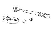
Commercial Service Tools |
|
|
|
|
||
|
AFS002PB |
|
|
|||
|
|
|
|
|
|
|
|
Tool name |
|
Description |
|
|
|
|
|
|
|
|
|
B |
|
1.Flare nut crowfoot |
|
|
|
|
|
|
|
|
|
|
C |
|
|
a: 10 mm (0.39 in) |
|
Removing and installing each brake piping |
|
||
|
2.Torque wrench |
|
|
|
|
|
|
|
S-NT360 |
|
|
|
D |
|
|
|
|
|
|
|
|
|
|
|
|
|
E |
|
|
|
|
|
|
|
|
|
|
|
|
|
BRC |
|
|
|
|
|
|
|
|
|
|
|
|
|
G |
|
|
|
|
|
|
H |
|
|
|
|
|
|
I |
|
|
|
|
|
|
J |
|
|
|
|
|
|
K |
|
|
|
|
|
|
L |
|
|
|
|
|
|
M |
Revision: 2005 March |
BRC-5 |
2005 X-Trail |
|
SYSTEM DESCRIPTION |
|
[ABS] |
|
|
SYSTEM DESCRIPTION |
PFP:00000 |
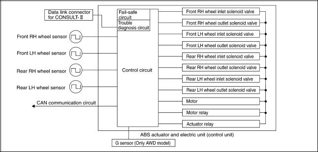
System Diagram |
AFS002LR |
Functions
ABS
SFIA2390E
AFS002P6
●The Anti-Lock Brake System is a function that detects wheel revolution while braking, and it improves handling stability during sudden braking by electrically preventing 4 wheel lock. Maneuverability is also improved for avoiding obstacles.
●Electrical System Diagnosis by CONSULT-II is available.
EBD
●Electronic Brake Distributor is a function that detects subtle slippages between front and rear wheels during braking, and it improves handling stability by electronically controlling Brake Fluid Pressure which results in reduced rear wheel slippage.
●Electrical System Diagnosis by CONSULT-II is available.
Operation That Is Not “System Error” |
AFS002P7 |
ABS
●When starting engine or just after starting vehicle, brake pedal may vibrate or the motor operating noise may be heard from engine room. This is a normal states of the operation check.
●During ABS operation, brake pedal lightly vibrates and a mechanical noise may be heard. This is normal.
●Stopping distance may be longer than that of vehicles without ABS when vehicle drives on rough, gravel, or snow-covered (fresh, deep snow) roads.
Fail-Safe Function |
AFS002LU |
ABS, EBD
In case of electrical malfunction with ABS, ABS warning lamp will turn on. In case of electrical incident with EBD, ABS warning lamp will turn on. Simultaneously, ABS become one of following conditions of Fail-Safe function.
1.For ABS malfunction, only EBD is activated and condition of vehicle is same condition of vehicles without ABS function.
NOTE:
In step 1 shown above, self-diagnosis when ignition switch is turned ON and when vehicle starts at initial time is performed. ABS self-diagnosis noise may be heard as usual.
2.For EBD malfunction, EBD and ABS become inoperative, and condition of vehicle is same as condition of vehicles without ABS, EBD function.
Revision: 2005 March |
BRC-6 |
2005 X-Trail |
SYSTEM DESCRIPTION
[ABS]
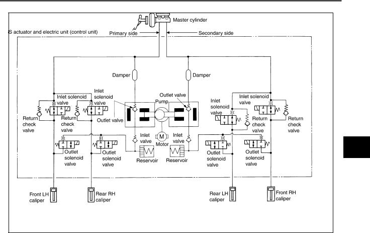
Hydraulic Circuit Diagram |
AFS002LV |
SFIA2479E
A
B
C
D
E
BRC
G
H
I
J
K
L
M
Revision: 2005 March |
BRC-7 |
2005 X-Trail |
|
CAN COMMUNICATION |
|
[ABS] |
|
|
CAN COMMUNICATION |
PFP:23710 |
System Description |
AFS002PX |
CAN (Controller Area Network) is a serial communication line for real time application. It is an on-vehicle multiplex communication line with high data communication speed and excellent error detection ability. Many electronic control units are equipped onto a vehicle, and each control unit shares information and links with other control units during operation (not independent). In CAN communication, control units are connected with 2 communication lines (CAN H line, CAN L line) allowing a high rate of information transmission with less wiring. Each control unit transmits/receives data but selectively reads required data only. Refer to LAN-16, "CAN Communication Unit" .
Revision: 2005 March |
BRC-8 |
2005 X-Trail |
TROUBLE DIAGNOSIS
|
[ABS] |
TROUBLE DIAGNOSIS |
PFP:00004 |
How to Perform Trouble Diagnosis for Quick and Accurate Repair |
AFS002LX |
INTRODUCTION |
|
●Most important point to perform diagnosis is to understand systems (control and mechanism) in vehicle thoroughly.
●It is also important to clarify customer complaints before inspection.
First of all, reproduce symptom, and understand it fully.
Ask customer about his/her complaints carefully. In some cases, it will be necessary to check symptom by driving vehicle with customer.
NOTE:
Customers are not professionals. Do not assume “maybe customer means...” or “maybe customer mentioned this symptom”.
EFJ0028D
●It is essential to check symptoms right from beginning in order to repair a malfunction completely.
For an intermittent malfunction, it is important to reproduce symptom based on interview with customer and past examples. Do not perform inspection on ad hoc basis. Most intermittent malfunctions are caused by poor contacts. In this case, it will be effective to shake suspected harness or connector by hand. When repairs are performed without any symptom check, no one can judge if malfunction has actually been eliminated.
●After diagnosis, make sure to perform “erase memory”. Refer to
BRC-20, "ERASE MEMORY" . |
SEF233G |
|
●For an intermittent malfunction, move harness or harness connector by hand to check poor contact or false open circuit.
●Always read “GI section” to confirm general precautions. Refer toGI-4, "General Precautions" .
A
B
C
D
E
BRC
G
H
I
J
K
L
M
Revision: 2005 March |
BRC-9 |
2005 X-Trail |
TROUBLE DIAGNOSIS
[ABS]
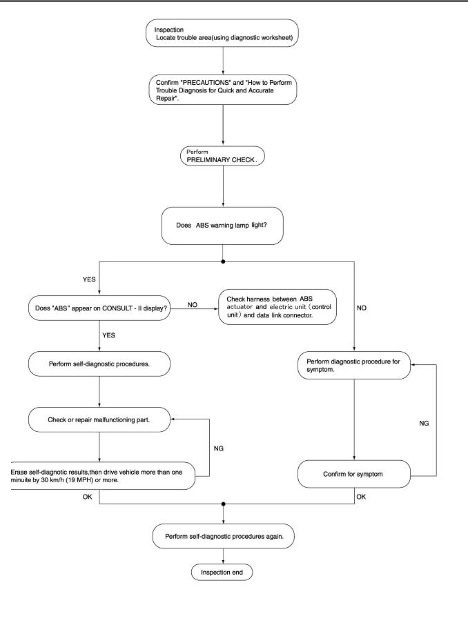
DIAGNOSIS FLOW CHART
SFIA0953E
Revision: 2005 March |
BRC-10 |
2005 X-Trail |
TROUBLE DIAGNOSIS
ASKING COMPLAINTS
●Complaints vary depending on the person. It is important to clarify the customer's actual remarks.
●Ask the customer about what symptoms are present and under what conditions. Use the information to reproduce the symptom while driving.
●It is also important to use diagnosis sheet so as not to miss vital information.
EXAMPLE OF DIAGNOSIS SHEET
[ABS]
A
B
C
D
SBR339B
E
BRC
G
H
I
J
K
L
M
LFIA0176E
Revision: 2005 March |
BRC-11 |
2005 X-Trail |

TROUBLE DIAGNOSIS
[ABS]
Component Parts Location |
AFS002LY |
SFIA2391E
Revision: 2005 March |
BRC-12 |
2005 X-Trail |

TROUBLE DIAGNOSIS
[ABS]
Schematic |
AFS002LZ |
A
B
C
D
E
BRC
G
H
I
J
K
L
M
TFWB0019E
Revision: 2005 March |
BRC-13 |
2005 X-Trail |

TROUBLE DIAGNOSIS
[ABS]
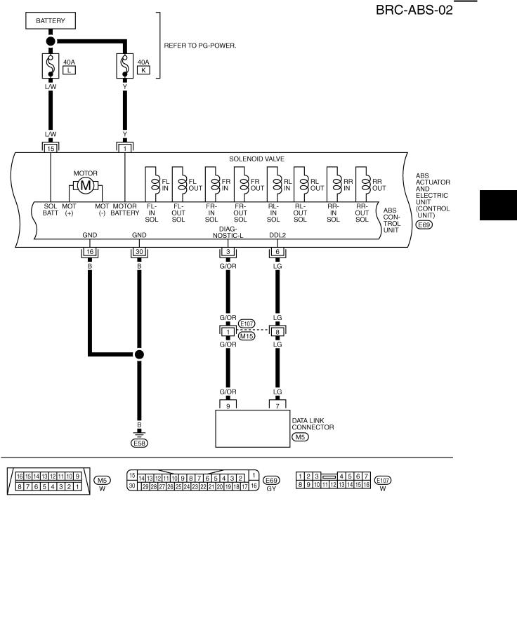
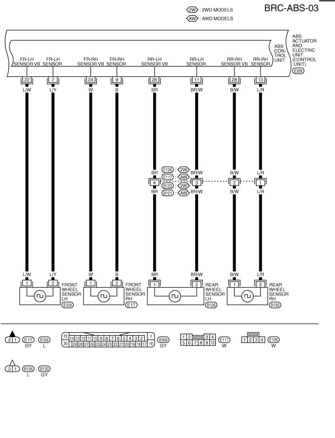
Wiring Diagram |
AFS002M0 |
TFWB0020E
Revision: 2005 March |
BRC-14 |
2005 X-Trail |
TROUBLE DIAGNOSIS
[ABS]
A
B
C
D
E
BRC
G
H
I
J
K
L
M
TFWB0003E
Revision: 2005 March |
BRC-15 |
2005 X-Trail |
TROUBLE DIAGNOSIS
[ABS]
TFWB0021E
Revision: 2005 March |
BRC-16 |
2005 X-Trail |
TROUBLE DIAGNOSIS
[ABS]
A
B
C
D
E
BRC
G
H
I
J
K
L
M
TFWB0022E
Revision: 2005 March |
BRC-17 |
2005 X-Trail |
TROUBLE DIAGNOSIS
|
[ABS] |
Control Unit Input/Output Signal Standard |
AFS002M1 |
REFERENCE VALUE FROM CONSULT-II |
|
CAUTION:
The display shows the control unit calculation data, so a normal value might be displayed even in the event the output circuit (harness) is open or short - circulated.
|
|
Data monitor |
|
|
|
|
|
|
|
|
|
|
Reference: Inspection |
Data monitor item |
Display item |
|
|
Reference values |
||
|
|
item |
||||
Condition |
|
in normal opera- |
||||
|
|
|
||||
|
|
|
|
|||
|
|
|
|
tion |
|
|
|
|
|
|
|
|
|
FR LH SENSOR |
Wheel speed calcu- |
Vehicle stopped |
|
0 [km/h] |
|
|
|
|
|
|
|
||
|
|
Nearly matches |
BRC-26, "Inspection 1: |
|||
FR RH SENSOR |
lated using signals |
|
|
|||
|
|
the speedometer |
||||
RR LH SENSOR |
from all four wheel |
Vehicle running (Note 1) |
|
Wheel Sensor Circuit" |
||
|
display (± |
10 % or |
||||
RR RH SENSOR |
sensors |
|
|
|||
|
|
|
||||
|
|
less) |
|
|
||
|
|
|
|
|
|
|
|
|
|
|
|
|
|
|
|
When vehicle is stopped on |
|
OFF |
|
|
|
|
level ground |
|
|
BRC-30, "Inspection 5: G |
|
DECEL G-SEN 1 |
Fore-and-aft gravity |
|
|
|
||
|
|
|
|
|||
|
|
|
|
Sensor Circuit (Only |
||
When G sensor is tilted toward |
|
|
|
|||
DECEL G-SEN 2 |
detected by G sensor |
|
|
|
||
|
|
|
AWD Models)" |
|||
the front with G sensor mount- |
|
ON |
|
|||
|
|
|
|
|||
|
|
|
|
|
||
|
|
ing nuts removed |
|
|
|
|
|
|
|
|
|
|
|
|
|
When the actuator solenoid |
|
ON |
|
BRC-29, "Inspection 4: |
|
|
operates or during a fail-safe |
|
|
||
|
|
|
|
|
||
ABS IN SOL |
Operation status of all |
|
|
|
ABS Actuator Relay or |
|
|
|
|
|
|||
When the actuator relay oper- |
|
|
|
|||
ABS OUT SOL |
solenoid valve |
|
|
|
ABS Motor Relay Power |
|
ates and the actuator solenoid |
|
OFF |
|
|||
|
|
|
|
Circuit" |
||
|
|
does not operate |
|
|
|
|
|
|
|
|
|
|
|
|
|
|
|
|
|
|
STOP LAMP SW |
Brake pedal operation |
Brake pedal depressed |
|
ON |
|
Stop lamp switch circuit |
|
|
|
|
|||
status |
|
|
|
|
||
Brake pedal not depressed |
|
OFF |
|
|||
|
|
|
|
|||
|
|
|
|
|
||
|
|
|
|
|
|
|
|
|
When the motor relay and |
|
ON |
|
|
|
Motor and motor relay |
motor are operating |
|
|
|
|
MOTOR RELAY |
|
|
|
|
||
|
|
|
|
|
||
operation status |
|
|
|
|
|
|
When the motor relay and |
|
OFF |
|
BRC-29, "Inspection 4: |
||
|
|
|
||||
|
|
|
|
|||
|
|
motor are not operating |
|
|
||
|
|
|
|
ABS Actuator Relay or |
||
|
|
|
|
|
||
|
|
|
|
|
|
|
|
|
|
|
|
|
ABS Motor Relay Power |
|
|
When the actuator relay is |
|
OFF |
|
|
|
|
|
|
Circuit" |
||
|
Actuator relay opera- |
operating |
|
|
||
|
|
|
|
|||
ACTUATOR RELAY |
|
|
|
|
||
|
|
|
|
|
||
tion status |
|
|
|
|
|
|
When the actuator relay is not |
|
ON |
|
|
||
|
|
|
|
|||
|
|
|
|
|
||
|
|
operating |
|
|
|
|
|
|
|
|
|
|
|
|
|
|
|
|
|
|
|
|
When ABS warning lamp is |
|
ON |
|
BRC-25, "BASIC |
|
|
ON |
|
|
||
|
ABS warning lamp on |
|
|
INSPECTION 3: |
||
ABS WARN LAMP |
|
|
|
|||
|
|
|
|
|||
condition (Note 2) |
|
|
|
|
INSPECTION OF ABS |
|
When ABS warning lamp is |
|
OFF |
|
|||
|
|
|
||||
|
|
|
|
WARNING LAMP" |
||
|
|
OFF |
|
|
||
|
|
|
|
|
||
|
|
|
|
|
|
|
|
|
|
|
|
|
|
|
Battery voltage sup- |
|
|
|
|
BRC-28, "Inspection 3: |
|
|
|
|
|
ABS Actuator and Elec- |
|
|
plied to ABS actuator |
|
|
|
|
|
BATTERY VOLT |
Ignition switch ON |
|
10 - 16 V |
|
tric Unit (Control Unit) |
|
and electric unit (con- |
|
|
||||
|
|
|
|
|
Power Supply and |
|
|
trol unit) |
|
|
|
|
|
|
|
|
|
|
Ground Circuit" |
|
|
|
|
|
|
|
|
|
|
|
|
|
|
|
|
|
EBD active |
|
ON |
|
|
EBD SIGNAL |
EBD operation |
ABS active |
|
|
|
|
|
|
|
|
|||
|
|
|
|
|
||
ABS SIGNAL |
ABS operation |
|
|
|
|
|
EBD not active |
|
OFF |
|
|
||
|
|
|
|
|
||
|
|
ABS not active |
|
|
EBD system |
|
|
|
|
|
|
||
|
|
|
|
|
|
|
|
|
|
|
|
|
ABS system |
|
|
EBD Fail |
|
ON |
|
|
|
|
|
|
|
||
EBD FAIL SIG |
System fail signal sta- |
ABS Fail |
|
|
|
|
|
|
|
|
|||
|
|
|
|
|
||
ABS FAIL SIG |
tus |
|
|
|
|
|
EBD normal |
|
OFF |
|
|
||
|
|
|
|
|
||
|
|
ABS normal |
|
|
|
|
|
|
|
|
|
|
|
|
|
|
|
|
|
|
Note 1: Confirm tire pressure is the standard value.
Note 2: ABS warning lamp ON/OFF timing.
ON: When the ignition switch is turned ON or when an error is detected.
OFF: After the ignition switch is turned ON (when system is normal).
Revision: 2005 March |
BRC-18 |
2005 X-Trail |
|
TROUBLE DIAGNOSIS |
|
|
[ABS] |
|
|
|
|
CONSULT-II Functions |
AFS002M2 |
|
CONSULT-II MAIN FUNCTION |
|
A |
In a diagnosis function (main function), there are "SELF-DIAGNOSTIC RESULTS", “DATA MONITOR”, "CAN DIAG SUPPORT MNTR", “ACTIVE TEST”, “FUNCTION TEST”, “ECU PART NUMBER”.
Diagnostic |
Function |
Reference |
|
test mode |
|||
|
|
||
|
|
|
|
SELF-DIAG- |
|
|
|
NOSTIC |
Self-diagnostic results can be read and erased quickly. |
BRC-19, "Self-Diagnosis" |
|
RESULTS |
|
|
|
|
|
|
|
DATA MONI- |
Input/Output data in the ABS actuator and electric unit (control unit) can be read. |
BRC-21, "Data Monitor" |
|
TOR |
|||
|
|
||
|
|
|
|
CAN DIAG |
|
LAN-13, "CAN Diagnostic |
|
SUPPORT |
The result of transmit/receive diagnostic of CAN communication can be read. |
||
Support Monitor" |
|||
MNTR |
|
||
|
|
||
|
|
|
|
|
Diagnostic Test Mode in which CONSULT-II drives some actuators apart from the |
|
|
ACTIVE TEST |
ABS actuator and electric unit (control unit) and also shifts some parameters in a |
BRC-23, "Active Test" |
|
|
specified range. |
|
|
|
|
|
|
|
|
Separate volume |
|
FUNCTION |
Performed by CONSULT-II instead of a technician to determine whether each sys- |
“CONSULT-II OPERATION |
|
TEST |
tem is “OK” or “NG”. |
MANUAL (FUNCTION |
|
|
|
TEST)” |
|
|
|
|
|
ECU PART |
ABS actuator and electric unit (control unit) part number can be read. |
— |
|
NUMBER |
|||
|
|
||
|
|
|
CONSULT-II BASIC OPERATION PROCEDURE
1.Touch “ABS” in the “SELECT SYSTEM” screen.
.
B
C
D
E
BRC
G
H
I
J
K
SFIA1816E
L
2.Select the required diagnostic location from the “SELECT DIAG MODE” screen.
M
|
SFIA2435E |
Self-Diagnosis |
AFS002PE |
OPERATION PROCEDURE |
|
1.Turn ignition switch OFF.
2.Connect CONSULT-II and CONSULT-II CONVERTER to data link connector.
3.Turn ignition switch ON.
4.Start engine and drive vehicle at 30 km/h (19 MPH) or more for approximately 1 minute.
5.After stopping vehicle, with the engine running, touch “START (NISSAN BASED VHCL)”, “ABS”, “SELFDIAG RESULTS” in order on the CONSULT-II screen.
Revision: 2005 March |
BRC-19 |
2005 X-Trail |

TROUBLE DIAGNOSIS
[ABS]
CAUTION:
If “START (NISSAN BASED VHCL)” is touched immediately after starting engine or turning on the ignition switch, “ABS” might not be displayed in the System Selection screen. In this case, repeat the operation from step 1.
6.The self-diagnostic results are displayed. (Touch “PRINT” to print out self-diagnostic results, if necessary.) ● Check ABS warning lamp if “NO FAILURE” is displayed.
7.Perform the appropriate inspection from the display item list, and repair or replace the malfunctioning component. Refer to BRC-20, "DISPLAY ITEM LIST" .
8.Start engine and drive vehicle at 30 km/h (19 MPH) or more for approximately 1 minute.
CAUTION:
When the wheel sensor malfunctions, after inspecting the wheel sensor system, the ABS warning lamp will not turn off even when the system is normal unless the vehicle is driving at approximately 30 km/h (19 MPH) or more for approximately 1 minute.
ERASE MEMORY
1.Turn ignition switch OFF.
2.Start engine and touch “START (NISSAN BASED VHCL)”, “ABS”, “SELF-DIAG RESULTS”, “ERASE MEMORY” in order on the CONSULT-II screen to erase the error memory.
CAUTION:
If the error memory is not erased, re-perform the operation from step 4.
3.Perform self-diagnosis again, and make sure that diagnostic memory is erased.
4.Drive vehicle at 30 km/h (19 MPH) or more for approximately 1 minute as the final inspection, and make sure that the ABS warning lamp is turned off.
DISPLAY ITEM LIST
Diagnostic item |
Malfunction is detected when... |
Check circuit |
|
|
|
|
|
FR LH SENSOR – 1 |
Circuit of front LH wheel sensor is open. |
|
|
|
|
|
|
RR RH SENSOR – 1 |
Circuit of rear RH wheel sensor is open. |
|
|
|
|
|
|
FR RH SENSOR – 1 |
Circuit of front RH wheel sensor is open. |
|
|
|
|
|
|
RR LH SENSOR – 1 |
Circuit of rear LH wheel sensor is open. |
|
|
|
|
|
|
|
When the circuit in the front LH wheel sensor is short-circuited. |
|
|
|
Or when the sensor power voltage is outside the standard. When |
|
|
FR LH SENSOR – 2 |
the distance between the wheel sensor and sensor rotor is too |
|
|
|
large and the sensor pulse cannot be recognized by the control |
|
|
|
unit. |
|
|
|
|
|
|
|
When the circuit in the rear RH wheel sensor is short-circuited. |
BRC-26, "Inspection 1: |
|
|
Or when the sensor power voltage is outside the standard. When |
||
RR RH SENSOR – 2 |
the distance between the wheel sensor and sensor rotor is too |
Wheel Sensor Circuit" |
|
|
large and the sensor pulse cannot be recognized by the control |
(Note 1) |
|
|
unit. |
|
|
|
|
|
|
|
When the circuit in the front RH wheel sensor is short-circuited. |
|
|
|
Or when the sensor power voltage is outside the standard. When |
|
|
FR RH SENSOR – 2 |
the distance between the wheel sensor and sensor rotor is too |
|
|
|
large and the sensor pulse cannot be recognized by the control |
|
|
|
unit. |
|
|
|
|
|
|
|
When the circuit in the rear LH wheel sensor is short-circuited. Or |
|
|
|
when the sensor power voltage is outside the standard. When |
|
|
RR LH SENSOR – 2 |
the distance between the wheel sensor and sensor rotor is too |
|
|
|
large and the sensor pulse cannot be recognized by the control |
|
|
|
unit. |
|
|
|
|
|
|
|
|
BRC-29, "Inspection 4: |
|
MAIN RELAY |
When the control unit detects an error in the actuator relay circuit. |
ABS Actuator Relay or |
|
ABS Motor Relay Power |
|||
|
|
||
|
|
Circuit" |
|
|
|
|
Revision: 2005 March |
BRC-20 |
2005 X-Trail |
TROUBLE DIAGNOSIS
[ABS]
Diagnostic item |
Malfunction is detected when... |
Check circuit |
|
|
|
|
|
FR LH IN ABS SOL |
When the control unit detects an error in the front left inlet sole- |
|
|
noid circuit. |
|
||
|
|
||
|
|
|
|
FR LH OUT ABS SOL |
When the control unit detects an error in the front left outlet sole- |
|
|
noid circuit. |
|
||
|
|
||
|
|
|
|
RR RH IN ABS SOL |
When the control unit detects an error in the rear right inlet sole- |
|
|
noid circuit. |
|
||
|
|
||
|
|
|
|
RR RH OUT ABS SOL |
When the control unit detects an error in the rear right outlet sole- |
BRC-29, "Inspection 4: |
|
noid circuit. |
|||
ABS Actuator Relay or |
|||
|
|||
|
|
||
|
|
ABS Motor Relay Power |
|
FR RH IN ABS SOL |
When the control unit detects an error in the front right inlet sole- |
||
Circuit" |
|||
noid circuit. |
|||
|
|||
|
|
||
|
|
|
|
FR RH OUT ABS SOL |
When the control unit detects an error in the front right outlet |
|
|
solenoid circuit. |
|
||
|
|
||
|
|
|
|
RR LH IN ABS SOL |
When the control unit detects an error in the rear left inlet sole- |
|
|
noid circuit. |
|
||
|
|
||
|
|
|
|
RR LH OUT ABS SOL |
When the control unit detects an error in the rear left outlet sole- |
|
|
noid circuit. |
|
||
|
|
||
|
|
|
|
|
|
BRC-28, "Inspection 3: |
|
|
When the ABS actuator and electric unit (control unit) |
ABS Actuator and Elec- |
|
LOW POWER VOLTAGE |
tric Unit (Control Unit) |
||
power voltage is lower than normal. |
|||
|
Power Supply and |
||
|
|
||
|
|
Ground Circuit" |
|
|
|
|
|
|
When there is an internal error in the ABS actuator and electric |
BRC-28, "Inspection 2: |
|
ABS CONTROLLER |
ABS Actuator and Elec- |
||
unit (control unit). |
|||
|
tric Unit (Control Unit)" |
||
|
|
||
|
|
|
|
CAN COMM CIRCUIT |
When there is an error in the CAN communication circuit. |
BRC-32, "Inspection 6: |
|
CAN Communication |
|||
|
|
||
|
|
Circuit" (Note 2) |
|
|
|
|
|
|
|
BRC-29, "Inspection 4: |
|
PUMP MOTOR |
During actuator motor operation with ON, when actuator motor |
ABS Actuator Relay or |
|
turns OFF or when control line for actuator motor relay is open. |
ABS Motor Relay Power |
||
|
|||
|
|
Circuit" |
|
|
|
|
|
|
G sensor is malfunctioning, or signal line of G sensor is open or |
BRC-30, "Inspection 5: |
|
G SENSOR (Only AWD model) |
G Sensor Circuit (Only |
||
shorted. |
|||
|
AWD Models)" |
||
|
|
||
|
|
|
Note 1: After completing repairs of shorted sensor circuit, when ignition switch is turned ON, ABS warning lamp turns on. Make sure that ABS warning lamp turns off while driving vehicle at 30 km/h (19 MPH) or more for approximately 1 minute according to self-diagnosis procedure. In addition, if wheel sensor 2 is displayed for wheels, check wheel sensor circuit and also check control unit power voltage.
Note 2: When errors are detected in several systems, including CAN communication circuit [U1000], troubleshoot CAN communication circuit. Refer to BRC-8, "CAN COMMUNICATION" .
Data Monitor |
AFS002PF |
OPERATION PROCEDURE
A
B
C
D
E
BRC
G
H
I
J
K
L
M
1.Touch “START (NISSAN BASED VHCL)”, “ABS”, “DATA MONITOR” in order on the CONSULT-II screen.
CAUTION:
When “START (NISSAN BASED VHCL)” is touched immediately after starting engine or turning on ignition switch, “ABS” might not be displayed in the system selection screen. In this case, repeat the operation from step 1.
2.At the monitor item selection screen, touch one of the items “ECU INPUT SIGNALS”, “MAIN SIGNALS” or. “SELECTION FROM MENU”.
3.Touch “START” to proceed to the data monitor screen.
Revision: 2005 March |
BRC-21 |
2005 X-Trail |

TROUBLE DIAGNOSIS
[ABS]
DISPLAY ITEM LIST
|
SELECT MONITOR ITEM |
|
|||
Data monitor item (Unit) |
|
|
|
Remarks |
|
ECU INPUT SIG- |
MAIN SIGNALS |
SELECTION |
|||
|
|
||||
|
NALS |
FROM MENU |
|
||
|
|
|
|||
|
|
|
|
|
|
FR LH SENSOR |
× |
× |
× |
Wheel speed calculated by front LH wheel |
|
[km/h] |
sensor signal is displayed. |
||||
|
|
|
|||
|
|
|
|
|
|
FR RH SENSOR |
× |
× |
× |
Wheel speed calculated by front RH wheel |
|
[km/h] |
sensor signal is displayed. |
||||
|
|
|
|||
|
|
|
|
|
|
RR LH SENSOR |
× |
× |
× |
Wheel speed calculated by rear LH wheel |
|
[km/h] |
sensor signal is displayed. |
||||
|
|
|
|||
|
|
|
|
|
|
RR RH SENSOR |
× |
× |
× |
Wheel speed calculated by rear RH wheel |
|
[km/h] |
sensor signal is displayed. |
||||
|
|
|
|||
|
|
|
|
|
|
DECEL G-SEN 1 |
|
|
|
|
|
(ON/OFF) |
× |
× |
× |
G sensor 1 (ON/OFF) status is displayed. |
|
(Only AWD model) |
|
|
|
|
|
|
|
|
|
|
|
DECEL G-SEN 2 |
|
|
|
|
|
(ON/OFF) |
× |
× |
× |
G sensor 2 (ON/OFF) status is displayed. |
|
(Only AWD model) |
|
|
|
|
|
|
|
|
|
|
|
FR LH IN SOL |
– |
× |
× |
Front left inlet ABS solenoid valve (ON/OFF) |
|
(ON/OFF) |
status is displayed. |
||||
|
|
|
|||
|
|
|
|
|
|
FR LH OUT SOL |
– |
× |
× |
Front left outlet ABS solenoid valve (ON/OFF) |
|
(ON/OFF) |
status is displayed. |
||||
|
|
|
|||
|
|
|
|
|
|
RR RH IN SOL |
– |
× |
× |
Rear right inlet ABS solenoid valve (ON/OFF) |
|
(ON/OFF) |
status is displayed. |
||||
|
|
|
|||
|
|
|
|
|
|
RR RH OUT SOL |
– |
× |
× |
Rear right outlet ABS solenoid valve (ON/ |
|
(ON/OFF) |
OFF) status is displayed. |
||||
|
|
|
|||
|
|
|
|
|
|
FR RH IN SOL |
– |
× |
× |
Front right inlet ABS solenoid valve (ON/OFF) |
|
(ON/OFF) |
status is displayed. |
||||
|
|
|
|||
|
|
|
|
|
|
FR RH OUT SOL |
– |
× |
× |
Front right outlet ABS solenoid valve (ON/ |
|
(ON/OFF) |
OFF) status is displayed. |
||||
|
|
|
|||
|
|
|
|
|
|
RR LH IN SOL |
– |
× |
× |
Rear left inlet ABS solenoid valve (ON/OFF) |
|
(ON/OFF) |
status is displayed. |
||||
|
|
|
|||
|
|
|
|
|
|
RR LH OUT SOL |
– |
× |
× |
Rear left outlet ABS solenoid valve (ON/OFF) |
|
(ON/OFF) |
status is displayed. |
||||
|
|
|
|||
|
|
|
|
|
|
STOP LAMP SW |
× |
× |
× |
Stop lamp switch (ON/OFF) status is dis- |
|
(ON/OFF) |
played. |
||||
|
|
|
|||
|
|
|
|
|
|
MOTOR RELAY |
– |
× |
× |
ABS motor relay (ON/OFF) condition is dis- |
|
(ON/OFF) |
played. |
||||
|
|
|
|||
|
|
|
|
|
|
ACTUATOR RLY |
– |
× |
× |
ABS actuator relay (ON/OFF) status is dis- |
|
(ON/OFF) |
played. |
||||
|
|
|
|||
|
|
|
|
|
|
ABS WARN LAMP |
– |
× |
× |
ABS warning lamp (ON/OFF) status is dis- |
|
(ON/OFF) |
played. |
||||
|
|
|
|||
|
|
|
|
|
|
BATTERY VOLT |
× |
× |
× |
The voltage supplied to the ABS actuator and |
|
(V ) |
electric unit (control unit) is displayed. |
||||
|
|
|
|||
|
|
|
|
|
|
EBD SIGNAL |
– |
– |
× |
EBD operation (ON/OFF) status is displayed. |
|
(ON/OFF) |
|||||
|
|
|
|
||
|
|
|
|
|
|
ABS SIGNAL |
– |
– |
× |
ABS operation (ON/OFF) status is displayed. |
|
(ON/OFF) |
|||||
|
|
|
|
||
|
|
|
|
|
|
EBD FAIL SIG |
– |
– |
× |
EBD fail-safe signal (ON/OFF) status is dis- |
|
(ON/OFF) |
played. |
||||
|
|
|
|||
|
|
|
|
|
|
ABS FAIL SIG |
– |
– |
× |
ABS fail-safe signal (ON/OFF) status is dis- |
|
(ON/OFF) |
played. |
||||
|
|
|
|||
|
|
|
|
|
|
× : Applicable
–: Not applicable
Revision: 2005 March |
BRC-22 |
2005 X-Trail |

TROUBLE DIAGNOSIS
[ABS]
Active Test |
AFS002PG |
CAUTION:
●Do not perform ACTIVE TEST while driving vehicle.
●Make sure to completely bleed air from the brake system.
●Active test cannot be performed when ABS or EBD operation is malfunction.
OPERATION PROCEDURE
1. Connect CONSULT-II and CONVERTER to data link connector and start engine.
2. Touch “START (NISSAN BASED VHCL)”, “ABS”, “ACTIVE TEST” in order on the CONSULT-II screen.
CAUTION:
When “START (NISSAN BASED VHCL)” is touched immediately after starting engine or turning on ignition switch, “ABS” might not be displayed in the system selection screen. In this case, repeat the operation from step 1.
A
B
C
D
3.The “ SELECT TEST ITEM” screen is displayed.
4.Touch necessary test item.
5.Touch “START” with “MAIN SIGNALS” line inverted.
6.ACTIVE TEST screen will be displayed, so perform the following test.
●Solenoid valve
●ABS motor
NOTE:
|
|
E |
|
|
|
|
|
BRC |
|
|
|
|
|
G |
SFIA2085E |
|
H |
|
|
I |
|
|
J |
●When active test is performed while depressing pedal, pedal depression amount will change, but this is normal.
●Approximately 10 seconds after operation has begun, “TEST STOP” will be displayed.
●To perform a retest after “TEST STOP” is displayed, touch “BACK” and perform test from step 3.
SOLENOID VALVE
NOTE:
The example shown is for the front right wheel. The procedure for the other wheels is the same as given below.
1.For ABS solenoid valve, touch “UP”, “KEEP”, and “DOWN”
Then use screen monitor to make sure solenoid valve operates as shown in Solenoid Valve Operation Chart. Refer to “Solenoid Valve Operation Chart”.
SFIA0678E
K
L
M
Revision: 2005 March |
BRC-23 |
2005 X-Trail |

TROUBLE DIAGNOSIS
[ABS]
Solenoid Valve Operation Chart
Operation |
|
|
|
ABS solenoid valve |
|
|
|
|
|
|
|
|
|
|
UP |
KEEP |
DOWN |
|
|
|
|
|
|
FR RH IN SOL |
|
OFF |
ON |
ON |
|
|
|
|
|
|
|
FR RH OUT SOL |
|
OFF |
OFF |
ON* |
|
|
|
|
|
|
|
*: ON for 1 to 2 seconds after the touch, and then OFF |
|
|
|
||
ABS MONITOR
Touch “ON”, “OFF” of the display screen, and make sure if ABS motor relay and ABS actuator relay are operating as given in the following table.
Operation |
ON |
OFF |
|
|
|
|
|
|
|
MOTOR RELAY |
ON |
OFF |
||
|
|
|
|
|
ACTUATOR RLY |
ON |
ON |
||
|
|
|
|
SFIA0593E |
|
|
|
|
|
For Fast and Accurate Diagnosis |
|
|
AFS002M4 |
|
PRECAUTIONS FOR DIAGNOSIS
●Be sure to check the procedures of “How to Perform Trouble Diagnosis” in advance. Refer toGI-4, "Gen- eral Precautions" .
●Always erase memory after completing trouble diagnosis. Refer to BRC-20, "ERASE MEMORY" .
●When checking continuity and voltage between units, be sure to check for disconnection, looseness, bend, or collapse for connector terminals. Repair or replace applicable part if any non-standard condition is detected.
●Intermittent malfunctions may be caused by a poor connection in the harness, connectors, and terminals. Move harnesses, harness connectors, and terminals by hand to make sure all connections are solid and undamaged.
●Do not to forcibly extend any connector terminal if a circuit tester is used for the check.
●The symptom shown in the table below may occur, but the system is operating normally.
Symptom |
Symptom description |
Result |
|
|
|
|
|
|
This is the operation noise of the motor in the actuator, and there may |
|
|
Motor operation noise |
be a slight sound during ABS operation. |
Normal |
|
|
|||
Just after the engine starts, the motor operating noise may be heard. |
|||
|
|
||
|
This is a normal status of the system operation check. |
|
|
|
|
|
|
System operation check |
When engine starts, “click” noise may be heard from engine room. This |
Normal |
|
noise |
is normal status of system operation check. |
|
|
|
|
|
|
|
When driving on roads with a low coefficient of friction, such as snowy |
|
|
ABS operation (Longer stop- |
roads or gravel roads, the stopping distance is sometimes longer for |
Normal |
|
ping distance) |
vehicles equipped with ABS. Therefore, when driving on such roads, |
||
|
|||
|
drive at a sufficiently reduced speed to be safe. |
|
|
|
|
|
ON and OFF Timing for ABS Warning Lamp
× : ON —: OFF
Condition |
ABS warning lamp |
|
|
Ignition switch OFF |
− |
|
|
When ignition switch is turned ON |
× |
|
|
After ignition switch is turned ON (When system is normal) |
− |
|
|
ABS error |
× |
|
|
EBD error |
× |
|
|
Revision: 2005 March |
BRC-24 |
2005 X-Trail |

TROUBLE DIAGNOSIS
|
[ABS] |
|
Basic Inspection |
AFS002M5 |
|
BASIC INSPECTION 1: BRAKE FLUID LEVEL, LEAKAGE AND BRAKE PAD |
|
A |
1.Check fluid level in the brake fluid reservoir tank. Refill the brake fluid if fluid level is low.
2.Check the area around the brake piping and ABS actuator and electric unit (control unit) for leakage. If
leakage or oozing is detected, check as follows:
●If ABS actuator and electric unit (control unit) connections are loose, tighten piping to the specified torque. Check again for leakage, and make sure that there is no fluid leakage.
● |
If the flare nuts at the connections and the threads of the actuator are damaged, replace the damaged |
|
parts. Then check again for leakage, and make sure that there is no fluid leakage. |
● |
If leakage or oozing is detected on parts other than actuator connections, wipe with a clean cloth and |
|
check again. If there is still leakage or oozing, replace the damaged part. |
● |
If leakage or oozing is detected on actuator body, wipe with a clean cloth and check again. If there is |
|
still leakage or oozing, replace ABS actuator and electric unit (control unit). |
|
CAUTION: |
|
ABS actuator and electric unit (control unit) cannot be disassembled. |
B
C
D
E
3.Check brake disc rotor and pads. Front disc rotor: BR-30, "DISC ROTOR INSPECTION" , Front pad: BR-
25, "PAD WEAR INSPECTION" , Rear disk rotor: BR-35, "DISC ROTOR INSPECTION" , Rear pad: BR- BRC 31, "PAD WEAR INSPECTION" .
BASIC INSPECTION 2: POWER SUPPLY CIRCUIT TERMINAL LOOSENESS AND BATTERY
Check battery for looseness on the battery positive/negative terminals and ground connection. Also make sure G that battery voltage does not drop.
BASIC INSPECTION 3: INSPECTION OF ABS WARNING LAMP
1.Make sure that when the ignition switch is turned ON, the ABS warning lamp turns on. If it is does not turn on, perform CAN communication circuit diagnosis. Refer to BRC-32, "Inspection 6: CAN Communication
Circuit" . Check ABS warning lamp if there is no malfunction in CAN communication circuit. Refer to BRC35, "Symptom 6: ABS Warning Lamp Indication Is Not Normal" .
2.Check if the ABS warning lamp turns off after the ignition switch is turned ON after the engine is started. If it does not turn off, perform self-diagnosis.
3. |
If ABS warning lamp has not turned off after 10 seconds the engine has been started, perform self-diagno- |
|
sis of the ABS actuator and electric unit (control unit). |
4. |
Always erase the self-diagnostic results after completing self-diagnosis. Refer to BRC-20, "ERASE MEM- |
|
ORY" . |
H
I
J
K
L
M
Revision: 2005 March |
BRC-25 |
2005 X-Trail |

TROUBLE DIAGNOSIS
|
[ABS] |
Inspection 1: Wheel Sensor Circuit |
AFS002M6 |
INSPECTION PROCEDURE |
|
Check each part according to CONSULT-II self-diagnostic results, and then identify the parts to be replaced.
CAUTION:
Do not check between wheel sensor terminals.
1. CHECK TIRES
Check air pressure, wear and size.
Are air pressure, wear and size within standard values?
YES |
>> GO TO 2. |
NO |
>> Adjust air pressure, or replace tire. |
2. CHECK SENSOR AND SENSOR ROTOR
●Check sensor rotor for damage. Refer to BRC-37, "SENSOR ROTOR" .
●Check wheel sensor for damage, disconnection or looseness. Refer to BRC-36, "WHEEL SENSORS" . OK or NG
OK |
>> GO TO 3. |
NG |
>> Repair wheel sensor mount or replace sensor rotor. |
3. CHECK SELF-DIAGNOSTIC RESULTS
Check the self-diagnostic results.
Self-diagnostic results
FR RH SENSOR-1, -2
FR LH SENSOR-1, -2
RRRH SENSOR-1, -2 RR LH SENSOR-1, -2
Is above displayed on self-diagnosis display?
YES |
>> GO TO 4. |
NO |
>> INSPECTION END |
4. CHECK CONNECTOR
1.Turn ignition switch OFF and disconnect ABS actuator and electric unit (control unit) connector and malfunctioning wheel sensor connector. Check terminal to see if it is deformed, disconnected, loose, etc., and repair or replace it if any malfunction condition is found.
2.Reconnect connectors, drive vehicle at 30 km/h (19 MPH) or more for approximately 1 minute, and then perform self-diagnosis.
Is the result of self-diagnosis normal?
YES |
>> Connector terminal contact is loose, damaged, open or shorted. |
NO |
>> GO TO 5. |
Revision: 2005 March |
BRC-26 |
2005 X-Trail |

TROUBLE DIAGNOSIS
[ABS]
5. CHECK WHEEL SENSOR HARNESS
1.Turn ignition switch OFF and disconnect malfunctioning wheel sensor connector and ABS actuator and electric unit (control unit) connector.
2.Check continuity between terminals. (Also check continuity when the steering wheel is turned right and left and when the sensor harness inside the wheel house is moved.)
SFIA2015E
|
|
|
Power supply circuit |
Signal circuit |
Ground circuit |
|
|||
|
|
|
|
|
|
|
|
|
|
|
|
|
ABS actuator |
|
ABS actuator |
|
|
|
|
|
|
|
and electric |
Wheel sensor |
and electric |
Wheel sensor |
ABS actuator and elec- |
|
|
|
|
|
unit (control |
unit (control |
tric unit (control unit) |
|
|
||
|
|
Wheel |
(harness con- |
(harness con- |
|
Ground |
|||
|
|
unit) |
unit) |
harness connector E69 |
|
||||
|
|
|
nector) |
nector) |
|
|
|||
|
|
|
harness con- |
harness con- |
(signal) |
|
|
||
|
|
|
|
|
|
|
|||
|
|
|
nector E69 |
|
nector E69 |
|
|
|
|
|
|
|
|
|
|
|
|
|
|
|
Front RH (E17) |
24 (W) |
1 (W) |
9 (B) |
2 (B) |
24 (W), 9 (B) |
|
|
|
|
|
|
|
|
|
|
|
|
|
|
Front LH (E59) |
22 (L/W) |
1 (L/W) |
7 (L/Y) |
2 (L/Y) |
22 (L/W), 7 (L/Y) |
|
— |
|
|
|
|
|
|
|
|
|
|
|
|
Rear RH(B130) |
28 (B/W) |
1 (B/W) |
13 (L/R) |
2 (L/R) |
28 (B/W), 13 (L/R) |
|
||
|
|
|
|||||||
|
|
|
|
|
|
|
|
|
|
|
Rear LH (B126) |
26 (BR) |
1 (BR) |
11 (BR/W) |
2 (BR/W) |
26 (BR), 11 (BR/W) |
|
|
|
|
|
|
|
|
|
|
|
|
|
|
|
Power supply circuit |
: Continuity should exist. |
|
|
|
|
||
|
|
Signal circuit |
: Continuity should exist. |
|
|
|
|
||
|
|
Ground circuit |
: Continuity should not exist. |
|
|
|
|||
OK or NG |
|
|
|
|
|
|
|
||
OK |
>> GO TO 6. |
|
|
|
|
|
|
||
NG |
>> Repair or replace harness and connector that have malfunction. |
|
|||||||
6. CHECK WHEEL SENSOR
A
B
C
D
E
BRC
G
H
I
J
K
1.Replace wheel sensor that resulted in malfunction by self-diagnosis.
2.Reconnect connectors, drive vehicle at 30 km/h (19 MPH) or more for approximately 1 minute, and then perform self-diagnosis.
Is above displayed on self-diagnosis display?
OK |
>> Wheel sensor has malfunction. |
NG |
>> ● Replace ABS actuator and electric unit (control unit). |
●Perform to self-diagnosis again, and make sure that the result shows “NO DTC IS DETECTED. FURTHER TESTING MAY BE REQUIRED”.
L
M
Revision: 2005 March |
BRC-27 |
2005 X-Trail |
TROUBLE DIAGNOSIS
[ABS]
Inspection 2: ABS Actuator and Electric Unit (Control Unit) |
AFS002M7 |
INSPECTION PROCEDURE
1. CHECK SELF-DIAGNOSTIC RESULTS
Check self-diagnostic results.
|
Self-diagnostic results |
|
|
|
|
|
|
|
ABS CONTROLLER |
|
|
|
|
|
|
Is above displayed on self-diagnosis display? |
|
||
YES |
>> Replace ABS actuator and electric unit (control unit), and perform self-diagnosis again. |
|
|
NO |
>> INSPECTION END |
|
|
Inspection 3: ABS Actuator and Electric Unit (Control Unit) Power Supply and |
|||
Ground Circuit |
AFS002M8 |
||
INSPECTION PROCEDURE
1. CHECK SELF-DIAGNOSTIC RESULTS
Check self-diagnostic results.
Self-diagnostic results
LOW POWER VOLTAGE
Is above displayed on self-diagnosis display?
YES |
>> GO TO 2. |
NO |
>> INSPECTION END |
2. CHECK CONNECTOR
1.Turn ignition switch OFF, disconnect the ABS actuator and electric unit (control unit) connector, and check the terminal for deformation, disconnection, looseness, and so on. If there is a malfunction, repair or replace the terminal.
2.Connect the connector securely and perform self-diagnosis again.
Is the result of self-diagnosis normal?
YES |
>> Connector terminal contact is loose, damaged, open or shorted. |
NO |
>> GO TO 3. |
Revision: 2005 March |
BRC-28 |
2005 X-Trail |
TROUBLE DIAGNOSIS
[ABS]
3. CHECK ABS ACTUATOR AND ELECTRIC UNIT (CONTROL UNIT) POWER SUPPLY AND GROUND
A
1.Turn ignition switch OFF and disconnect ABS actuator and electric unit (control unit) connector.
2.Turn ignition switch ON or OFF, and then check continuity and voltage between each connector terminal
and ground.
|
|
ABS actuator and elec- |
|
|
Measure- |
|
|
Measured |
|
|||
Signal |
|
tric unit (control unit) |
Ground |
ment con- |
|
|
||||||
|
|
|
|
|
value |
|||||||
|
|
harness connector E69 |
|
|
dition |
|
|
|
|
|||
|
|
|
|
|
|
|
|
|
|
|||
|
|
|
|
|
|
|
|
|
|
|
|
|
|
|
|
|
|
Ignition |
|
Battery voltage |
|||||
|
|
|
|
— |
switch |
|
||||||
|
|
|
|
|
(Approx. 12 V) |
|||||||
Power |
|
|
|
|
|
ON |
|
|||||
|
29 (L) |
|
|
|
|
|
|
|
|
|
||
|
|
|
|
|
|
|
|
|
|
|
||
supply |
|
|
|
|
|
|
|
|
|
|
|
|
|
|
Ignition |
|
|
|
|
|
|
||||
|
|
|
|
|
|
|
|
|
|
|||
|
|
|
|
|
|
|
|
|
|
|
||
|
|
|
|
— |
switch |
|
|
Approx. 0 V |
||||
|
|
|
|
|
OFF |
|
|
|
|
|
|
|
|
|
|
|
|
|
|
|
|
|
|
||
|
|
|
|
|
|
|
|
|
|
|||
|
|
ABS actuator and elec- |
|
|
|
Measure- |
|
Measured |
||||
Signal |
|
tric unit (control unit) |
|
Ground |
ment con- |
|
||||||
|
|
|
value |
|||||||||
|
|
harness connector E69 |
|
|
|
dition |
|
|
|
|||
|
|
|
|
|
|
|
|
|
|
|||
|
|
|
|
|
|
|
|
|
|
|
||
|
|
|
|
|
|
Ignition |
|
|
Continuity |
|||
Ground |
|
16 (B), 30 (B) |
|
— |
|
switch |
|
|
should |
|||
|
|
|
|
|
|
OFF |
|
|
|
exist. |
||
|
|
|
|
|
|
|
|
|
|
|
|
|
OK or NG |
|
|
|
|
|
|
|
|
|
|
||
OK |
|
>> Check battery for terminal looseness, low voltage, etc. If |
||||||||||
|
|
any malfunction is found, repair malfunctioning parts. |
||||||||||
NG |
|
>> Corresponding harness circuit malfunctions. Repair cir- |
||||||||||
|
|
cuit, and perform self-diagnosis again. |
|
|
||||||||
SFIA2087E
SFIA2089E
B
C
D
E
BRC
G
H
I
Inspection 4: ABS Actuator Relay or ABS Motor Relay Power Circuit |
AFS002M9 |
||
INSPECTION PROCEDURE |
|
J |
|
|
|
||
1. CHECK ABS ACTUATOR AND ELECTRIC UNIT (CONTROL UNIT) POWER SUPPLY AND GROUND |
|||
CIRCUIT |
|
K |
|
Check the self-diagnostic results. |
|
|
|
|
|
|
L |
Self-diagnostic results |
|
||
FR LH IN ABS SOL
FR LH OUT ABS SOL
M
RR RH IN ABS SOL
RR RH OUT ABS SOL
FR RH IN ABS SOL
FR RH OUT ABS SOL
RR LH IN ABS SOL
RR LH OUT ABS SOL
MAIN RELAY
PUMP MOTOR
Is above displayed on self-diagnosis display?
YES |
>> GO TO 2. |
NO |
>> INSPECTION END |
Revision: 2005 March |
BRC-29 |
2005 X-Trail |

TROUBLE DIAGNOSIS
[ABS]
2. CHECK CONNECTOR
1.Turn ignition switch OFF, disconnect the ABS actuator and electric unit (control unit) connector, and check the terminal for deformation, disconnection, looseness, and so on. If there is a malfunction, repair or replace the terminal.
2.Connect the connector securely and perform self-diagnosis again.
Is the result of self-diagnosis normal?
YES |
>> Connector terminal contact is loose, damaged, open or shorted. |
NO |
>> GO TO 3. |
3. CHECK ABS ACTUATOR RELAY OR ABS MOTOR RELAY POWER SUPPLY CIRCUIT
1.Turn ignition switch OFF and disconnect ABS actuator and electric unit (control unit) connector.
2.For the ABS actuator relay, measure voltage between the harness connector terminal 15 (L/W) and ground. For the ABS motor relay, measure voltage between the harness connector terminal 1 (Y) and ground.
ABS actuator and electric |
|
|
|
|
|
unit (control unit) harness |
Ground |
Voltage |
|||
|
connector E69 |
|
|
|
|
|
|
|
|
|
|
|
1 (Y), 15 (L/W) |
— |
Battery voltage |
||
|
(Approx. 12 V) |
||||
|
|
|
|||
|
|
|
|
|
SFIA2110E |
OK or NG |
|
|
|||
|
|
|
|
||
OK |
>> GO TO 4. |
|
|
|
|
NG |
>> Circuit malfunction between the battery and ABS actuator and electric unit (control unit). Repair |
||||
|
circuit. |
|
|
|
|
4. CHECK ABS ACTUATOR AND ELECTRIC UNIT (CONTROL UNIT) GROUND CIRCUIT
Check continuity between ABS actuator and electric unit (control unit) harness connector E69 terminals 16(B), 30(B) and ground.
ABS actuator and electric unit |
|
|
|
|
|
|
(control unit) |
Ground |
Continuity |
|
|
|
harness connector E69 |
|
|
|
|
|
|
|
|
|
|
|
16 (B), 30 (B) |
— |
Yes |
|
|
|
|
|
|
|
|
OK or NG |
|
|
|
|
|
OK |
>> Replace ABS actuator and electric unit (control unit). |
|
|||
NG |
>> Open or short in harness. Repair or replace the harness, |
SFIA2089E |
|||
|
and perform self-diagnosis again. |
|
|
|
|
Inspection 5: G Sensor Circuit (Only AWD Models) |
AFS002P9 |
||||
INSPECTION PROCEDURE |
|
|
|
|
|
1. CHECK SELF-DIAGNOSTIC RESULTS |
|
|
|
||
|
|
|
|
|
|
Check the self-diagnostic results.
Self-diagnostic results
G SENSOR
Is above displayed on self-diagnosis display?
YES |
>> GO TO 2. |
NO |
>> INSPECTION END |
Revision: 2005 March |
BRC-30 |
2005 X-Trail |
Loading...