


 Loading...
K ELECTRICAL
SECTION WW
WIPER, WASHER & HORN
CONTENTS
A
B
C
D
E
PRECAUTIONS ......................................................... |
|
2 |
Precautions for Supplemental Restraint System |
|
|
(SRS) “AIR BAG” and “SEAT BELT PRE-TEN- |
|
|
SIONER” ................................................................. |
|
2 |
Wiring Diagrams and Trouble Diagnosis ................. |
|
2 |
FRONT WIPER AND WASHER SYSTEM ................. |
|
3 |
System Description ................................................. |
|
3 |
WIPER OPERATION ........................................... |
|
3 |
WASHER OPERATION ........................................ |
|
4 |
Wiring Diagram — WIPER — ............................. |
..... 5 |
|
Terminal and Reference Values for Combination |
|
|
Switch ...................................................................... |
|
6 |
Removal and Installation of Front Wiper Arms, |
|
|
Adjustment of Wiper Arms Stop Location ................ |
|
6 |
Removal and Installation of Wiper Motor and Link- |
|
|
age .......................................................................... |
|
7 |
REMOVAL ............................................................ |
|
7 |
INSTALLATION .................................................... |
|
7 |
Front Washer Nozzle Adjustment ............................ |
|
8 |
Front Washer Tube Layout ...................................... |
|
9 |
Removal and Installation of Front Washer Nozzle..... |
9 |
|
REMOVAL ............................................................ |
|
9 |
INSTALLATION .................................................... |
|
9 |
Inspection of Front Washer Nozzle ......................... |
|
9 |
CHECK VALVE .................................................... |
|
9 |
Removal and Installation of Wiper and Washer |
|
|
Switch .................................................................... |
|
10 |
REMOVAL .......................................................... |
|
10 |
INSTALLATION .................................................. |
|
10 |
Removal and Installation of Washer Tank ............. |
|
10 |
REMOVAL .......................................................... |
|
10 |
INSTALLATION .................................................. |
|
10 |
Removal and Installation of Washer Motor ........... |
|
10 |
REMOVAL .......................................................... |
|
10 |
INSTALLATION ................................................... |
|
11 |
REAR WIPER AND WASHER SYSTEM ................. |
12 |
Wiring Diagram — WIP/R — ............................... |
... 12 |
Terminal and Reference Values for Combination |
|
Switch .................................................................... |
14 |
Removal and Installation of Rear Wiper Arms, |
|
Adjustment for Wiper Arms Stop Location ............. |
14 |
Removal and Installation of Wiper Motor and Link- |
|
age ......................................................................... |
15 |
REMOVAL .......................................................... |
15 |
INSTALLATION .................................................. |
15 |
Washer Nozzle Adjustment ................................... |
16 |
Removal and Installation of Rear Washer Nozzle... 16 |
|
REMOVAL .......................................................... |
16 |
INSTALLATION .................................................. |
16 |
Inspection of Rear Washer Nozzle ........................ |
16 |
CHECK VALVE ................................................... |
16 |
Removal and Installation of Wiper and Washer |
|
Switch .................................................................... |
17 |
Removal and Installation of Washer Tank ............. |
17 |
Removal and Installation of Washer Motor ............ |
17 |
Rear Washer Tube Layout ..................................... |
17 |
HORN ....................................................................... |
18 |
Wiring Diagram — HORN — ............................... |
... 18 |
Removal and Installation ....................................... |
19 |
REMOVAL .......................................................... |
19 |
INSTALLATION .................................................. |
19 |
POWER SOCKET .................................................... |
20 |
Wiring Diagram –POWER SOCKET– ................... |
20 |
Removal and Installation of Front Power Socket |
... 21 |
REMOVAL .......................................................... |
21 |
INSTALLATION .................................................. |
21 |
Removal and Installation of Rear Power Socket |
... 21 |
REMOVAL .......................................................... |
21 |
INSTALLATION .................................................. |
21 |
F
G
H
I
J
WW
L
M
Revision: 2005 March |
WW-1 |
2005 X-Trail |
|
PRECAUTIONS |
|
|
PRECAUTIONS |
PFP:00011 |
Precautions for Supplemental Restraint System (SRS) “AIR BAG” and “SEAT BELT PRE-TENSIONER” AKS00BBD
The Supplemental Restraint System such as “AIR BAG” and “SEAT BELT PRE-TENSIONER”, used along with a front seat belt, helps to reduce the risk or severity of injury to the driver and front passenger for certain types of collision. Information necessary to service the system safely is included in the SRS and SB section of this Service Manual.
WARNING:
●To avoid rendering the SRS inoperative, which could increase the risk of personal injury or death in the event of a collision which would result in air bag inflation, all maintenance must be performed by an authorized NISSAN/INFINITI dealer.
●Improper maintenance, including incorrect removal and installation of the SRS, can lead to personal injury caused by unintentional activation of the system. For removal of Spiral Cable and Air Bag Module, see the SRS section.
●Do not use electrical test equipment on any circuit related to the SRS unless instructed to in this Service Manual. SRS wiring harnesses can be identified by yellow and/or orange harnesses or harness connectors.
Wiring Diagrams and Trouble Diagnosis |
AKS00BBE |
When you read wiring diagrams, refer to the followings:
●Refer to GI-14, "How to Read Wiring Diagrams" in GI section.
●Refer to PG-2, "POWER SUPPLY ROUTING" for power distribution circuit in PG section. When you perform trouble diagnosis, refer to the followings:
●Refer to GI-10, "HOW TO FOLLOW TEST GROUPS IN TROUBLE DIAGNOSES" in GI section.
●Refer to GI-26, "How to Perform Efficient Diagnosis for an Electrical Incident" in GI section.
Revision: 2005 March |
WW-2 |
2005 X-Trail |

FRONT WIPER AND WASHER SYSTEM
FRONT WIPER AND WASHER SYSTEM |
PFP:28810 |
System Description |
AKS00BBF |
WIPER OPERATION |
|
The wiper switch is controlled by a lever built in combination switch.
There are three wiper switch positions
●LO speed
●HI speed
●INT (Intermittent)
With the ignition switch in ON or START position, power is supplied
●through 20A fuse [No. 6, located in fuse block (J/B)]
●to front wiper motor terminal 2
●to combination switch (front wiper and washer switch) terminal 15.
Low and High Speed Wiper Operation
Ground is supplied
●to combination switch (front wiper and washer switch) terminal 17
●through grounds E24 and E50.
When the wiper switch is placed in the LO position, ground is supplied
●through combination switch (front wiper and washer switch) terminal 14
●to front wiper motor terminal 3.
With power and ground supplied, the wiper motor operates at low speed.
When the wiper switch is placed in the HI position, ground is supplied
●through combination switch (front wiper and washer switch) terminal 16
●to front wiper motor terminal 5.
With power and ground supplied, the wiper motor operates at high speed.
Auto Stop Operation
With wiper switch turned OFF, wiper motor will continue to operate until wiper arms reach windshield base. When wiper arms are not located at base of windshield with wiper switch OFF, ground is provided
●from combination switch (front wiper and washer switch) terminal 14
●to front wiper motor terminal 3, in order to continue wiper motor operation at low speed. Ground is also supplied
●through combination switch (front wiper and washer switch) terminal 13
●to front wiper motor terminal 4
●through front wiper motor terminal 1
●through grounds E24 and E50.
When wiper arms reach base of windshield, front wiper motor terminals 2 and 4 are connected instead of terminals 1 and 4. Wiper motor will then stop wiper arms at the STOP position.
Intermittent Operation
The front wiper motor operates the wiper arms one time at low speed at a set interval of approximately 1 to 13 seconds. This feature is controlled by the wiper amplifier (INT SW) combined with front wiper and washer switch.
When the wiper switch is placed in the INT position, ground is supplied to wiper amplifier.
The desired interval time is input to wiper amplifier (INT VR) from variable intermittent wiper volume combined with front wiper and washer switch.
Then intermittent ground is supplied
●through wiper amplifier (OUTPUT) and
●through combination switch (front wiper and washer switch) terminal 14
●to front wiper motor terminal 3.
The wiper motor operates at low speed at the desired interval.
A
B
C
D
E
F
G
H
I
J
WW
L
M
Revision: 2005 March |
WW-3 |
2005 X-Trail |

FRONT WIPER AND WASHER SYSTEM
WASHER OPERATION
With the ignition switch in the ON or START position, power is supplied
●through 20A fuse [No. 6, located in fuse block (J/B)]
●to front washer motor terminal 1.
When the lever is pulled to the WASH position, ground is supplied
●from grounds E24 and E50
●through combination switch (front wiper and washer switch) terminal 17, and
●through combination switch (front wiper and washer switch) terminal 18
●to front washer motor terminal 2.
With power and ground supplied, the washer motor operates.
When the lever is pulled to the WASH position for one second or more, the wiper motor operates at low speed for approximately 3 seconds to clean windshield. This feature is controlled by the wiper amplifier in the same manner as the intermittent operation.
Revision: 2005 March |
WW-4 |
2005 X-Trail |

FRONT WIPER AND WASHER SYSTEM
Wiring Diagram — WIPER —
AKS00BBG
A
B
C
D
E
F
G
H
I
J
WW
L
M
TKWB0190E
Revision: 2005 March |
WW-5 |
2005 X-Trail |
FRONT WIPER AND WASHER SYSTEM
Terminal and Reference Values for Combination Switch |
AKS00BBH |
|||||||
|
|
|
|
|
|
|
|
|
Terminal |
|
Wire |
Item |
|
Condition |
Voltage |
||
|
|
|
|
|||||
No. |
|
color |
|
|
|
|||
|
|
Ignition switch |
Condition or operation |
|
|
|||
|
|
|
|
|
|
|||
|
|
|
|
|
|
|
|
|
13 |
|
L/Y |
Front wiper auto |
ON |
Wiper operating |
Approx. 0V |
||
|
|
|
|
|
||||
|
stop signal |
|
|
|
|
|||
|
Wiper stopped |
Battery voltage |
||||||
|
|
|
|
|||||
|
|
|
|
|
||||
|
|
|
|
|
|
|
|
|
14 |
|
L |
Front wiper motor |
ON |
Wiper switch |
OFF |
Battery voltage |
|
|
|
|
|
|||||
|
operation signal (LO) |
|
|
|
||||
|
LO |
Approx. 0V |
||||||
|
|
|
|
|
||||
|
|
|
|
|
|
|||
|
|
|
|
|
|
|
|
|
15 |
|
Y/G |
Ignition ON signal |
ON |
— |
Battery voltage |
||
|
|
|
|
|
|
|
|
|
16 |
|
L/B |
Front wiper motor |
ON |
Wiper switch |
OFF |
Battery voltage |
|
|
|
|
|
|||||
|
operation signal (HI) |
|
|
|
||||
|
HI |
Approx. 0V |
||||||
|
|
|
|
|
||||
|
|
|
|
|
|
|||
|
|
|
|
|
|
|
|
|
17 |
|
B/W |
Ground |
OFF |
— |
Approx. 0V |
||
|
|
|
|
|
|
|
|
|
18 |
|
G |
Front washer switch |
ON |
Washer switch |
ON |
Approx. 0V |
|
|
|
|
|
|||||
|
signal |
|
|
|
||||
|
OFF |
Battery voltage |
||||||
|
|
|
|
|
||||
|
|
|
|
|
|
|||
|
|
|
|
|
|
|
|
|
Removal and Installation of Front Wiper Arms, Adjustment of Wiper Arms Stop |
||||||||
Location |
|
|
|
|
|
AKS00BBI |
||
1.Prior to wiper arm installation, turn on wiper switch to operate wiper motor and then turn it “OFF” (Auto Stop).
2.Lift the blade up and then set it down onto glass surface to set the blade center to clearance “L1” & “L2” immediately before tightening nut.
3.Eject washer fluid. Turn on wiper switch to operate wiper motor and then turn it “OFF”.
4.Ensure that wiper blades stop within clearance “L1” & “L2”.
● Clearance “L1” |
: 49.2 - 64.2 mm (1.937 - 2.528 in) |
|
● Clearance “L2” |
: 39.3 - 54.3 mm (1.547 - 2.138 in) |
PKIA7843E |
● Tighten wiper arm nuts to specified torque.
Front wiper arm nut |
: 23.6 N·m (2.4 kg-m, 17 ft-lb) |
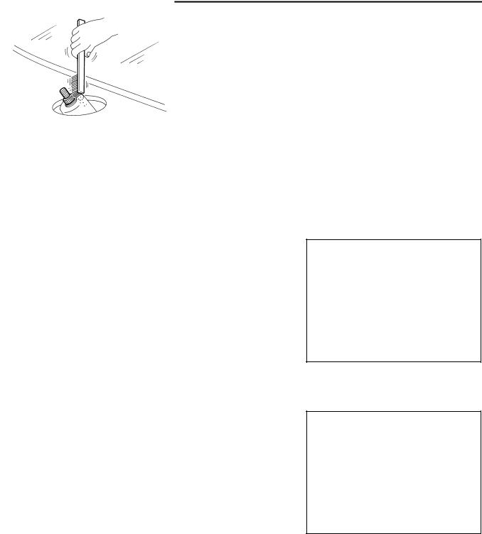
●Before reinstalling wiper arm, clean up the pivot area as illustrated. This will reduce possibility of wiper arm looseness.
SEL024J
Revision: 2005 March |
WW-6 |
2005 X-Trail |
FRONT WIPER AND WASHER SYSTEM
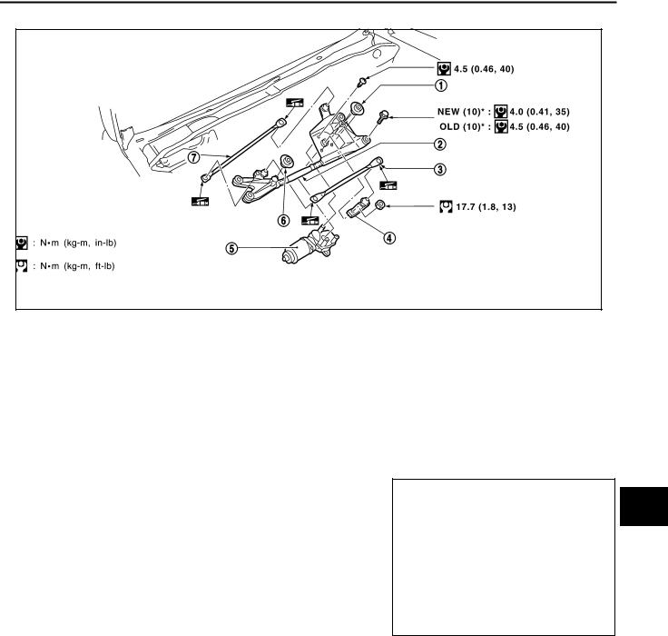
Removal and Installation of Wiper Motor and Linkage |
AKS00BBJ |
SKIB3133E
*: In regard to the notation of torque in the illustration, “NEW” shows an ISO standard, “OLD” shows a conventional standard,nda the measurements of hexagonal width across flats are in parentheses. For the identification in case of the same width across flats, refer to GI-45, "Tightening Torque Table (New Standard Included)" .
1. |
Rubber |
2. |
Wiper frame |
3. |
Wiper link |
4. |
Motor arm |
5. |
Wiper motor |
6. |
Rubber |
7.Wiper link
A
B
C
D
E
F
G
H
REMOVAL
1.Operate wiper motor, and stop it at the upper limit position.
2.Remove wiper arm from the vehicle.
3.Remove cowl top cover. Refer to EI-19, "COWL TOP" .
4.Remove screws (4) and remove wiper motor assembly from the vehicle.
5.Disconnect wiper motor connector.
6.Remove wiper link from wiper frame.
7.Remove wiper motor from wiper frame.
PKIA8628E
INSTALLATION
1.Connect wiper motor to connector. Turn wiper switch ON to operate wiper motor, then turn wiper switch OFF (auto stop).
2.Disconnect wiper motor connector.
3.Install wiper motor to wiper frame.
4.Install wiper motor assembly to the vehicle.
I
J
WW
L
M
Revision: 2005 March |
WW-7 |
2005 X-Trail |
Loading...