


Primera
Table of contents
 Loading...
LT-1
LIGHTING SYSTEM
K ELECTRICAL
CONTENTS
C
D
E
F
G
H
I
J
L
M
SECTION
A
B
LT
LIGHTING SYSTEM
PRECAUTION ............................................................ 4
Precautions for Supplemental Restraint Sy stem
(SRS) “AIR BAG” and “SEATBELT PRE-TEN-
SIONER” .................................................................. 4
Precaution ................................................................ 4
Wiring Diagrams and Trouble Diagnosis .................. 4
HEADLAMP -CONVENTIONAL TYPE- ..................... 5
System Description .................................................. 5
DESCRIPTION ...................................................... 5
LOW BEAM OPERATION ..................................... 5
HIGH BEAM OPERATION/FLASH-TO-PASS
OPERATION ......................................................... 5
Wiring Diagram — H/LAMP — ................................. 6
Trouble Diagnoses . .................................................. 7
Aiming Adjustment ................................................... 7
LOW BEAM ........................................................... 8
Bulb Replacement .................................................... 9
HEADLAMP ..........................................................9
CLEARANCE LAMP, FRONT TURN SIGNAL
LAMP .................................................................... 9
Removal and Installation ..........................................9
REMOVAL ............................................................. 9
INSTALLATION ..................................................... 9
HEADLAMP - XENON TYPE - ................................. 10
System Description ................................................ 10
LOW BEAM OPERATION ................................... 10
HIGH BEAM OPERATION/FLASH-TO-PASS
OPERATION ....................................................... 10
Wiring Diagram - H/LAMP - .................................... 12
Trouble Diagnosis .................................................. 14
Aiming Adjustment ................................................. 15
LOW BEAM ......................................................... 15
Bulb Replacement .................................................. 16
XENON BULB (LOW BEAM) .............................. 16
HIGH BEAM ........................................................ 16
CLEARANCE LAMP, FRONT TURN SIGNAL
LAMP .................................................................. 17
Removal and Installation ........................................ 17
REMOVAL ........................................................... 17
INSTALLATION ................................................... 17
HEADLAMP (WITHDAYTIME)- CONVENTIONAL
TYPE - ....................................................................... 18
System Description .................................................18
DESCRIPTION ....................................................18
HEADLAMP OPERATION ..................................18
DAYTIME LIGHT OPERATION ...........................18
Schematic ...............................................................19
Wiring Diagram — H/LAMP — ...............................20
Trouble Diagnoses .................................................23
Aiming Adjustment ..................................................2 4
Bulb Replacement ..................................................24
HEADLAMP .........................................................24
CLEARANCE LAMP, FRONT TURN SI GNAL
LAMP ...................................................................24
HEADLAMP (WITH DAYTIME) - XENON TYPE - .... 25
System Description .................................................25
Schematic ...............................................................26
Wiring Diagram - DTRL - ........................................27
Trouble Diagnoses .................................................30
DAYTIME LIGHT UNIT INSPECTION TABLE .....3 0
Bulb Replacement ..................................................30
Aiming Adjustment ..................................................3 0
HEADLAMP AIMING CONTROL (M ANUAL) ..........31
Wiring Diagram — H/AIM — ...................................31
Removal an d Installation ........................................32
Switch Circuit Inspection ........................................32
HEADLAMP AIMING CONTROL (AUTO) ................ 33
System Description .................................................33
Component Parts and Harness ..............................33
CONNECTOR LOCATION ..................................33
Wiring Diagram - H/AIM - .......................................34
CONSULT-II ............................................................36
CONSULT-II INSPECTION PROCEDURE ..........36
CONSULT-IIDIAGNOSTICTESTMODEFUNC-
TION ....................................................................37
INITIALIZATION ..................................................37
SELF-DIAGNOSTIC RESULTS ITEM CHART ....38
Check Power and Ground for Height Sens or .........38
Check LightingSwitch Circuit .................................39
Check Speed Signal Circuit Chec k .........................39

LT-2
Check Headlamp Aiming Motor ..............................40
Removal and installation .........................................41
TURN SIGNAL AND HAZARD WARNING LAMPS... 42
System Description .................................................42
TURN SIGNAL OPERATION ...............................42
HAZARD LAMP OPERATION .............................43
MULTI-REMOTE CONTROL SYSTEM OPERA-
TION ....................................................................43
Wiring Diagram — TURN — ...................................45
Terminaland Reference Valvefor Smart Entrance
Control Unit .............................................................47
Turn Signal And Hazard Warning Lamp Do Not
Operate ...................................................................47
Turn S ignal Lamps Do Not Operate Bu t Hazard
Warning Lamp Do Operate .....................................48
Hazard WarningLamps Do Not Operate But Turn
Signal Lamp Do Operate ........................................49
Turn Signal Lamps LH Do Not Operate ..................51
Turn Signal Lamps R H Do Not Operate .................52
LH and RH Turn Indicators Do Not Operate ...........53
Bulb Re placement ..................................................54
FRONT TURN SIGNAL LAMP ............................54
SIDE TURN SIGNAL LAMP ................................54
REAR TURN SIGNAL LAMP ...............................54
RemovalandInstallationforS ideTurnSignalLamp...54
RemovalandInstallationforRearTurnSignalLamp...54
LIGHTING AND TURN SIGNAL SWITCH ................ 55
Removal and Installation ........................................55
Switch Circuit Inspection ........................................55
HAZARD SWITCH ....................................................56
Removal and Installation ........................................56
REMOVAL ...........................................................56
INSTALLATION ....................................................56
STOP L AMP ..............................................................57
Wiring Diagram — STOP/L — ................................57
Bulb Re placement ..................................................59
STOP LAMP ........................................................59
Removal and Installation ........................................59
STOP LAMP ........................................................59
BACK-UP LAMP .......................................................60
Wiring Diagram — BACK/L — ................................60
Bulb Replacement (Sedan) ....................................62
Bulb Replacement (Wagon) ....................................62
Removal a nd Installation (Sedan) ...........................62
Removal a nd Installation (Wagon) ..........................62
PARKING, LICENSE PLATE AND TAIL LAMPS ......63
Wiring Diagram - TAIL/L -/LHD MODELS ...............63
Wiring Diagram - TAIL/L -/RHD MODELS ..............66
Bulb Re placement ..................................................69
PARKING AND TAIL LAMPS ...............................69
LICENSE PLATE LAMP ......................................69
Removal and Installation ........................................69
PARKING AND TAIL LAMPS ...............................69
LICENSE PLATE LAMP ......................................69
FRONT FOG LAMP ..................................................71
System Description .................................................71
DESCRIPTION ....................................................71
FOG LAMP OPERATION ....................................71
Wiring Diagram — F/FOG — ..................................72
Aiming Adjustment ..................................................73
Bulb Replacement ...................................................73
Removal and Installation .........................................73
REMOVAL ............................................................73
INSTALLATION ....................................................74
REAR FOG LAMP .....................................................75
Wiring Diagram — R/FOG — /Without Front Fog
Lamp ....................................................................... 75
WiringDiagram—R/FOG—/WithFrontFogLamp...76
Bulb Replacement (Sedan) .....................................79
Bulb Replacement (Wagon) ....................................79
Removal and Installation .........................................79
REMOVAL (SEDAN) ............................................79
INSTALLATION (SEDAN) ....................................79
CLEARANCE LAMP/TAIL LAMP .............................80
Bulb Replacement (Clearance Lamp) .....................80
Bulb Replacement(Tail Lamp) ................................ 80
Removal and Installation of Clearance Lamp .........80
Removal and Installation of Tail Lamp ....................80
HIGH-MOUNTED STOP LAMP .................................81
Bulb Replacement ...................................................81
HIGH-MOUNTED STOP LAMP (SEDAN) ...........81
HIGH-MOUNTED STOP LAMP (WAGON) ..........81
Removal and Installation .........................................81
HIGH-MOUNTED STOP LAMP (SEDAN) ...........81
HIGH-MOUNTED STOP LAMP (WAGON) ..........81
REAR COMBINATION LAMP ...................................82
Wiring Diagram —STOP/L— ..................................82
Bulb Replacement (Sedan) .....................................84
Bulb Replacement (Wagon) ....................................84
Removal and Installation .........................................84
REMOVAL (SEDAN) ............................................84
INSTALLATION .................................................... 84
COMBINATION SWITCH ..........................................86
Removal and Installation .........................................86
Switch Circuit Inspection .........................................87
ILLUMINATION ..........................................................89
System Description .................................................89
Schematic ...............................................................90
Wiring Diagram ....................................................... 91
INTERIOR ROOM L AMP ..........................................96
System Description .................................................96
POWER SUPPLY AND GROUND .......................96
SWITCH O PERATION ......................................... 97
INTERIOR ROOM LAMP TIMER OP ERATION...97
ON-OFF CONTROL .............................................97
Schematic ...............................................................98
Wiring Diagram - ROOM/L -/LH D MODELS ...........99
Wiring Diagram - ROOM/L -/RHD MODELS .........103
Terminal and Reference Valve for Smart Entrance
Control Unit ...........................................................107
CONSULT-II Inspection Procedure .......................107
“ROOM LAMP” ...................................................107
CONSULT-II Application Items ..............................108
ROOM LAMP .....................................................108
Interior Room Lamp Timer Does Not Operate ......109
Interior Room Lamp Timer Does Not C ancel ........114

LT-3
C
D
E
F
G
H
I
J
L
M
A
B
LT
Bulb Replacement .................................................118
INTERIOR ROOM LAMP ...................................1 18
STEP LAMP .......................................................119
ASHTRAY ..........................................................1 19
Removal and Installation .......................................119
INTERIOR ROOM LAMP ...................................1 19
STEP LAMP .......................................................119
ASHTRAY ..........................................................1 19
SPOT,VANITYMIRRORAND TRUNK(LUGGAGE)
ROOM LAMPS ....................................................... 120
Wiring Diagram — INT/L — ................................. 120
Bulb Replacement ................................................ 123
SPOT LAMP ...................................................... 123
TRUNK ROOM LAMP ....................................... 123
LUGGAGE ROOM LAMP ................................. 123
Removal and Installation ...................................... 123
SPOT LAMP ...................................................... 123
TRUNK ROOM LAMP ....................................... 123
LUGGAGE ROOM LAMP ................................. 124
CAN COMMUNICATION ........................................ 125
System De scription .............................................. 125
CANCommunicationUnitForLHDModel swithTyre
Pressure Monitoring System ................................ 125
TYPE 1 .............................................................. 126
TYPE 2 .............................................................. 127
TYPE 3 .............................................................. 128
TYPE 4 .............................................................. 129
TYPE 5 .............................................................. 130
TYPE 6 .............................................................. 131
CANCommunicationUnitForLHDModelswithout
Tyre Pressure Monitoring System ........................132
TYPE 7 ..............................................................133
TYPE 8 ..............................................................134
TYPE 9 ..............................................................135
TYPE 10 ............................................................136
TYPE 11 ............................................................137
TYPE 12 ............................................................138
CAN Communication Unit For RHD Models with
Tyre Pressure Monitoring System ........................139
TYPE 13 ............................................................140
TYPE 14 ............................................................141
TYPE 15 ............................................................142
TYPE 16 ............................................................143
TYPE 17 ............................................................144
TYPE 18 ............................................................145
CANCommunicationUnitForRHDModelswithout
Tyre Pressure Monitoring System ........................146
TYPE 19 ............................................................147
TYPE 20 ............................................................148
TYPE 21 ............................................................149
TYPE 22 ............................................................150
TYPE 23 ............................................................151
TYPE 24 ............................................................152
BULB SPECIFICATIONS ........................................153
Headlamp .............................................................153
Exterior Lamp .......................................................153
Interior Lamp/Illumination .....................................153

LT-4
PRECAUTION
PRECAUTION
PFP:00011
Precautions for Supplemental Restraint System (SRS) “AIR BAG” and “SEAT
BEL T PRE-TENSIONER”
EKS003T7
The Supplemental Restraint System s uch as "AIR BAG" and "SEAT BELT PRE- TENSIONER", used along
with a front seat belt, helps to reduce the ris k or severity of injury to the driver and front passenger for certain
types of collision. Information necessary to service the system safely is included in the SRS and SB section of
this Service Manual.
WARNING:
● To avoid rendering the SRS inoperative, which could increase the risk of personal injury or death
in the event of a collision which would result in air bag inflation, all maintenance must be per-
formed by an authorized NISSAN/INFINIT I dealer.
● Improper maintenance, including incorrect removal and installation of the SRS, can lead to per-
sonal injury caused by unintentional activatio n of the system. For removal of Spiral Cable and Air
Bag Module, see the SRS section.
● Do not use electrical test equipment on any circuit related to the SR S unless instructed to in this
Service Manual. SRS wiring harnesses can be identified by yellow and/or orange harness connec-
tors.
Precaution
EKS003T8
● Do not touch the glass of bulb d irectly by hand. Keep grease and other oily matters away from it. Do not
touch bulb by hand w hile it is lit or right after being turned off. Burning may result.
● Do not leave bulb out of headlamp reflector for a long time because dust, moisture smoke, etc. ma y affect
the per formance of the headlamp. When replacing the bulb, be sure to replace i t with a new one.
● Adjust aiming by tightening aiming screw. (To adjust it toward loosening side, first loosen adjusting screw,
and then make adjustment by tightening.)
● To remove soil or sealant of bulbs, do not use organic solvent (thinner, gasoline, etc.)
● When replacing bulb, be sure to hold bulb socket and pull it out straight. If wiring harness of the bulb is
pulled at an angle, the bulb may be caught in the lamp, making it difficult to take out.
Wiring Diagrams and Trouble Diagnosis
EKS003T9
When you rea d wiring diagrams, refer to the following:
● Refer to GI-14, "How to Read Wiring Diagrams" in GI section
● Refer to PG- 3, "POWER SUPPLY ROUTING" for power distribution circuit in PG section
When you per form trouble diagnosis, refer to the following:
● Refer to GI-11,"HOW TO FOLLOW TEST GR OUPS IN TROUBLE DIAGNOSES" in GI section
● Refer toGI-24, "How to Perform Efficient Diagnosis for an Electrical Incident" in GI section

HEADLAMP -CONVENTIONAL TYPE-
LT-5
C
D
E
F
G
H
I
J
L
M
A
B
LT
HEADLAMP -CONVENTIONAL TYPE- PFP:26010
System Description
EKS004P6
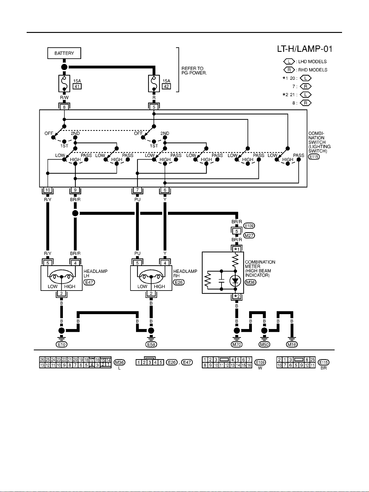
DESCRIPTION
The headlamps are controlled by the lighting switch which is built into the combination switch.
Power is supplied at all times
● to lighting switch terminal 8
● through 15A fuse (No. 41, located in the fuse and fusible link box), and
● to lighting switch terminal 5
● through 15A fuse (No. 42, located in the fuse and fusible link box).
LOW B EAM OPERATION
When the lighting swi tch is turned to the 2ND posi tion and placed in LOW (“B”) position, power is supplied
● from lighting switch terminal 10
● to terminal 5 of the headlamp LH, and
● from lighting switch terminal 7
● to terminal 5 of the headlamp RH.
Terminal 2 of ea ch headlamp supplies ground through body grounds E10 and E58.
With power and ground supplied, the low beams will illuminate.
HIGH BEAM OPERATION/FLASH-TO-PASS OPERATION
When the lighting switch is turned to the 2ND position and placed in HIGH (“A”) position or PASS (“C”) posi-
tion, power is supplied
● from lighting switch terminal 9
● to terminal 4 of headlamp LH, and
● to combination meter terminal 20 (LHD models) or 7 (RHD models) for the HIGH BEAM in dicator.
● from lighting switch terminal 6
● to terminal 4 of headlamp RH.
Ground is supplied to terminal 21 (LHD models) or 8 (RHD models) of the c ombination meter through body
grounds M16, M50 and M70.
Ground is supplied to terminal 2 of each headlamp thr ough body grounds E10 and E58.
With power and ground supplied, the high beams and the HIGH BEAM indicator illuminate.
LT-6
HEADLAMP -CONVENTIONAL TYPE-
Wiring Diagram — H/LAMP —
EKS004P7
MKWA0001E

HEADLAMP -CONVENTIONAL TYPE-
LT-7
C
D
E
F
G
H
I
J
L
M
A
B
LT
T rouble Diagnoses
EKS004P8
Aiming Adjustment
EKS004P9
When performing headlamp aiming adjustment, use an aiming machine, aiming wall screen or headlamp
tester. Aimers should be in good repair, calibrated and operated in accordance with respective operation man-
uals.
If any aimer is not available, aiming adjustment can be done as follows:
For details, refer to the regulations in your own country.
● Keep all tires inflated to correct pressures.
● Place vehicle and tester on one and same flat surface.
● See that there is no-load in vehicle (coolant, engine oil filled up to correct level and full fuel tank) other
than the driver (or equivalent weight pla ced in driver′s position).
Symptom Possible cause Repairorder
LH headlamps do not operate.
1. Bulb
2.G rounds E10 and E58
3.15A fuse
4. Lighting switch
1.Check bulb.
2.Check grounds E10 and E58.
3.Check 15A fuse (No. 41, located in fuse
and fusible link box).
Verify battery positive voltage is present
at terminal 8 of lighting switch.
4.Check lighting switch.
RH headlamps do not operate.
1. Bulb
2.G rounds E10 and E58
3.15A fuse
4. Lighting switch
1.Check bulb.
2.Check grounds E10 and E58.
3.Check 15A fuse (No. 42, located in fuse
and fusible link box).
Verify battery positive voltage is present
at terminal 5 of lighting switch.
4.Check lighting switch.
LH high beam does not operate, but LH
low beam operates.
1. Bulb
2.O pen in LH high beams circuit
3. Lighting switch
1.Check bulb.
2. Check continuity between lighting switch
terminal 9 (BR/R) and LH headlamp ter-
minal 4 (BR/R) for an open circuit.
3.Check lighting switch.
LH low beam does not operate, but LH
high beam operates.
1. Bulb
2.Open in LH lo w beam circuit
3. Lighting switch
1.Check bulb.
2. Check continuity between lighting switch
terminal10 (R/Y) and LH headlamp ter-
minal 5 (R/Y) for an open circuit.
3.Check lighting switch.
RH high beam does not operate, but RH
low beam operates.
1. Bulb
2.O pen in RH high beams circuit
3. Lighting switch
1.Check bulb.
2. Check continuity between lighting switch
terminal 6 (Y) and RH headlamp termi-
nal 4 (Y) for an open circuit.
3.Check lighting switch.
RH low beam does not operate, but RH
high beam operates.
1. Bulb
2.Open in RH low beam circuit
3. Lighting switch
1.Check bulb.
2. Check continuity between lighting switch
terminal 7 (PV) and RH headlamp termi-
nal5(PV)foranopencircuit.
3.Check lighting switch.
High beam indicator does not work.
1. Bulb
2.G rounds M16, M50 and M70
3.O pen in high beam circuit
1.Check bulb in combination meter.
2.Check grounds M16, M50 andM70.
3. Check continuity between lighting switch
terminal 9 (BR/R) and combination
meter terminal 20 (BR/R) LHD or 7 (BR/
R) RHD for an open circuit.
LT-8
HEADLAMP -CONVENTIONAL TYPE-
CAUTION:
Be sure aiming switch is set to “0” when performing aiming adjustment.
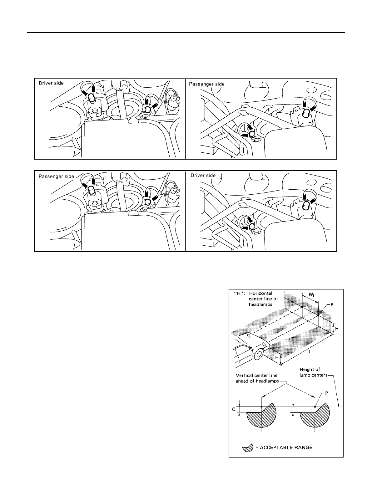
LOW BEAM
1. Turn headlamp low beam on.
LHD models
RHD models
2. Use adjusting pots to perform aiming adjustment.
● First tighten the adjusting pot all the way and then make adjustment by loosening the pot.
If the vehicle front body has been repaired and/or the headlamp assembly has been replaced, check aim-
ing. Use the aiming chart shown in the figure.
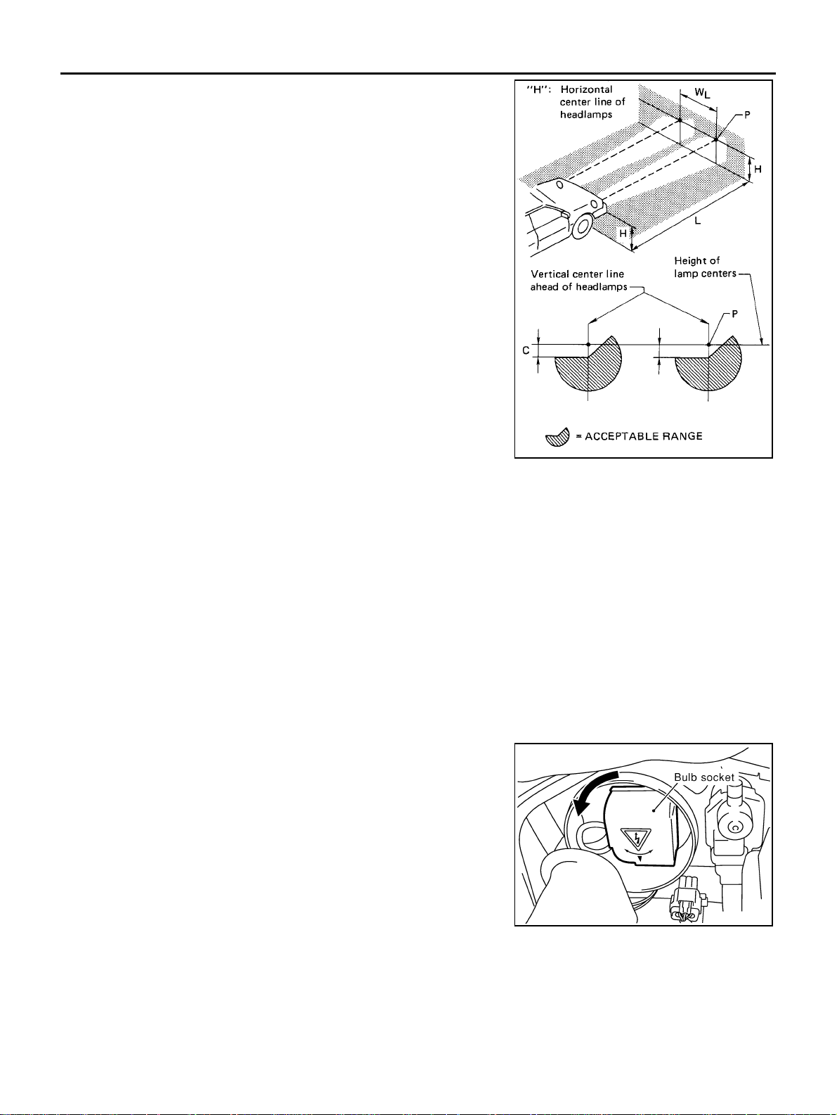
● Adjust headlamps so that main axis of light is parallel to cen-
ter line of body and is aligned with point P shown in illustra-
tion.
● Figure to the left shows headlamp aiming pattern for driving
on right side of road; for driving on left side of road, aiming
pattern is reversed.
● Dotted lines to point P in illustrati on show center of headlamp.
● Basic illum inating area for adjustment should be within the
range shown in the figure. Adjust headlamps accordingly.
CAUTION:
Be sure aiming switch is set to “0” when preforming aiming
adjustment .
“H” : Horizontal center line of headlamps
“W
L
”
: Distance between each headlamp center
“L” : 25 m (98.43 in)
“C” : 250 mm (9.84 in)
MKIA0048E
MKIA0049E
SEL254L

HEADLAMP -CONVENTIONAL TYPE-
LT-9
C
D
E
F
G
H
I
J
L
M
A
B
LT
Bulb Replacement
EKS004PA
HEADLAMP
1. Disconnect connector of headlamp.
2. Unlock retaining spring, then remove bulb.
CLEARANCE LAMP, FRONT TURN SI GNAL LAMP
1. Turn the bulbsocket counterclockwise and unlock it.
2. Remove the bulb from its socket.
CAUTION:
● Do not touch the glass of bulb directly by hand. Keep grease and other oily matters away from it.
Do not touch bulb by hand while it is lit or right after being turned off. Burning may result.
● Do not leave bulb out of headlamp reflector for a long time because dust, moisture smoke, etc.
may affect the performance of headlamp. When replacing bulb, be sure to replace it with new one.
● When bulb is installed, be sure to lock rubber cap to ensure watertightness.
Removal and Installation
EKS004PB
REMOVAL
1. Disconnect connector of headlamp and clearance lamp.
2. Remove the front gr ille. Refer to EI-12, "
FRONT GRILL" .
3. Remove the headlamp mounting bolts.
4. Pull the headlamp toward the front of the vehicle.
INSTALLATION
● Install in the reverse order of removal, taking ca re of the following points.
Headlamp mounting screws and nu t
Headlamp (Low) : 12V - 55W (H7)
Headlamp (High) : 12V - 55W (H7)
MKIB0116E
Clearance lamp : 12V - 5W
Front turn signal lamp : 12V - 21W
MKIB0117E
Tightening torque : 4.4 - 5.8 N·m (0.45 - 0.59 kg-m, 39 - 51 in-lb)

LT-10
HEADLAMP - XENON TYPE -
HEADLAMP - XENON TYPE -
PFP:26010
System Description
EKS004PC
The headlamps are controlled by lighting swi tch which is built into the combination switch.
Power is supplied at all times
● to lighting switch terminal 8
● through 15A fuse (No. 41, located in the fuse and fusible link box) and
● to lighting switch terminal 5
● through 15A fuse (No. 42, located in the fuse and fusible link box) and
● to headlamp LH relay terminal 3
● through 20A fuse (No. 37, located in the fuse and fusible link box) and
● to headlamp RH relay terminal 3
● through 20A fuse (No. 36, located in the fuse and fusible link box).
LOW BEAM OPERATION
When the lighting switch is turned to the 2ND position and placed in LOW (“B”) position, power is supplied
● from terminal 5 of each headl amp relay
● to terminal 5 of each headlamps
Terminal 3 of each headlamp supplies ground through body grounds E 10 and E58.
With power and ground supplied, the low beams will illuminates.
HIGH BEAM OPERATION/FLASH-TO-PASS OPERATION
When the lighting switch is turned to 2ND position and placed in HIGH (“A”) position or PASS (“C”) position,
power is suppli ed.
● from lighting switch terminal 6
● to terminal 4 of headlamp RH, and
● from lighting switch terminal 9
● to terminal 4 of headlamp LH, and
● to combination meter termina l 20 (LHD models) or 7 (RH D models) for the HIGH BEAM indicator.
Ground is supplied to terminal 21 (LHD models) or 8 (RHD models) of the combination meter through body
grounds M16, M50 and M70.
Ground is supplied to terminal 2 of each headlamp through body grounds E10 and E58.
With power and ground supp lied, the high beams and HIGH BEAM indicator illuminate.
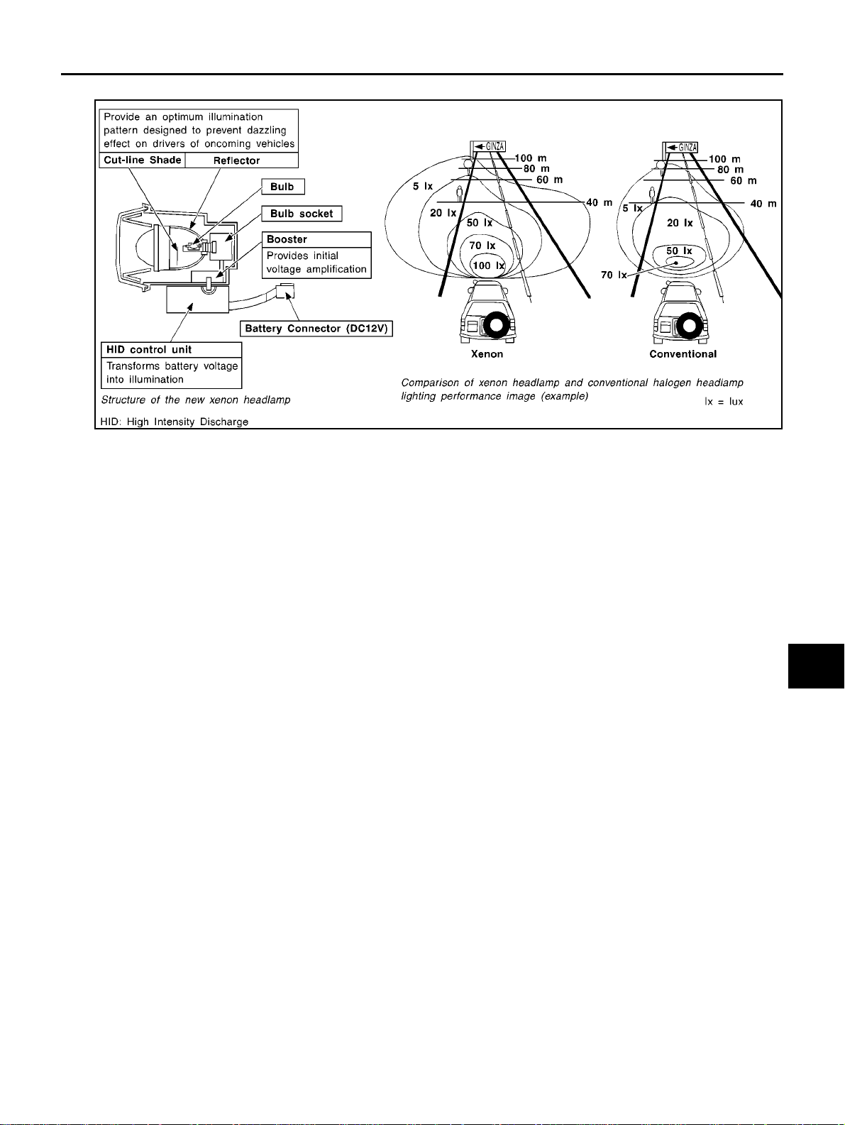
Xenon type headlamp is adopted to the low beam headlamps. Xenon bulbs do not use a filament. Instead,
they produce light when a high v oltage current is passed between two tungsten electrodes through a mixture
of xenon (an insert gas) and certain other metal hal ides. In addition to added lighting power, electronic control
of the power supply gives the headlamps stable quality and tone color.
Following are so me of the many advantage of the xenon type headlamp.
● The light produced by the headlamps is white color approximating sunlight that is easy on the eyes.
● Light output is nearly double that of halogen headlamps, affor ding increased area of illumination.
● The light features a high relative spectral distribution at wav elengths to the human eye is most sensitive,
which means that even in the rain, more light is reflected back from the road surface toward the vehicle,
for add ed visibility.
HEADLAMP - XENON TYPE -
LT-11
C
D
E
F
G
H
I
J
L
M
A
B
LT
● Power consumption is approximately 25 percent less than halogen headlamps, reducing battery loa d.
SEL440V

LT-12
HEADLAMP - XENON TYPE -
Wiring Diagram - H/LAMP -
EKS004PD
MKWA0002E

HEADLAMP - XENON TYPE -
LT-13
C
D
E
F
G
H
I
J
L
M
A
B
LT
MKWA0003E

LT-14
HEADLAMP - XENON TYPE -
WARNING:
● The xenon headlamp has a high-tension current generating area. Be extremely careful when
removing and installing. Be certain to disconnect the battery negative cable prior to removing or
installing.
● When the xenon headlamp is lit, do not touch the harness (covered with red or amber insulation),
bulb itself or the bulb socket with your bare hands.
● Never service a xenon headlamp with wet hands.
● When checking body side harness with a circuit tester, be certain to disconnect the harness con-
nector from the xenon headlamp.
● When the xenon headlamp is lit, the xenon bulb must be installed in the headlamp housing. (Never
turn on xenon headlamp, if the bulb is out of the headlamp housing.)
CAUTION:
Make sure to install the bulb securely; if the xenon bulb is improperly installed in its socket, high-ten-
sion current leaks occur. This may lead to a melted bulb and/or bulb socket.
T rouble Diagnosis
EKS004PE
HID:High Intensity Discharge
Symptom Possible cause Repair order
LH or RH xenon headlamp (low beam)
blinks, lacks brightness or does not illumi-
nate.
1.20A fuse
2.Relay
3.Power supply circuitto headlamp low
beam
4.Xenon bulb
5.HID controlunit and booster
1.Check 20Afuse[No.37: LH, No. 36: RH,
locatedinfuseandfusiblelinkbox].
2.Check Headlamp relay.
3.Verify battery positive voltage is present
at terminal 5 of headlamp harness with
lighting switch in “2nd” and “Low” posi-
tions.(Beforeinspectingheadlamp ter-
minal, disconnect headlamp connector
with lighting switch in “OFF” position.)
4.Replace the xenon bulb with the other
side bulb or new one. (If headlamps illu-
minatecorrectly, replace the bulb.)
5.ReplacetheHIDcontrolunitandbooster
as a headlamp assembly.
LH or RH [both headlamp high and xenon
(low) beam] do not illuminate.
1.Bulb
2.15A fuse
3.Relay
4.Ground circuit
1.Check bulb.
2.Check 15A fuse [No. 41: LH, No. 42
locatedinfuseandfusiblelinkbox].
3.Check headlamp relay.
4.Check continuity between headlamp ter-
minal 2 and body ground. (Before
inspecting headlamp terminal, discon-
nect headlamp connectorwith lighting
switch in “OFF” position.)
LH or RH headlamp high beam does not
illuminate.
1.Bulb
2.Power supply circuitto headlamp high
beam
1.Check bulb.
2.Verify battery positive voltage is present
at terminal 2, 3 of headlamp harness
with lighting switch in “2nd” and “HIGH”
position. (Before inspecting headlamp
terminal, disconnect headlamp connec-
tor with lighting switch in “OFF” po sition.)
High beam indicator does not work.
1.Bulb
2.Grounds M16, M50 and M70
3.Open in high beam circuit
1.Check bulb in combinationmeter.
2.Check grounds M16, M50 and M70.
3.Check continuity betweenlighting switch
terminal 9 (BR/R) and combination
meter terminal20 (BR/R) LHD or 7 (BR/
R) RHD for an open circuit.
HEADLAMP - XENON TYPE -
LT-15
C
D
E
F
G
H
I
J
L
M
A
B
LT
Aiming Adjustment
EKS004PF
When performing headlamp aiming adjustment, use an aiming machine, aiming wall screen or headlamp
tester. Aimers should be in good repair, calibrated and operated in accordance with respective operation man-
uals.
If any aimer is not available, aiming adjustment can be done as follows:
For details, refer to the regulations in your own country.
● Keep all tires inflated to correct pressures.
● Place vehicle and tester on one and same flat surface.
● See that there is no-load in vehicle (coolant, engine oil filled up to correct level and full fuel tank) other
than the driver (or equivalent weight pla ced in driver′s position).
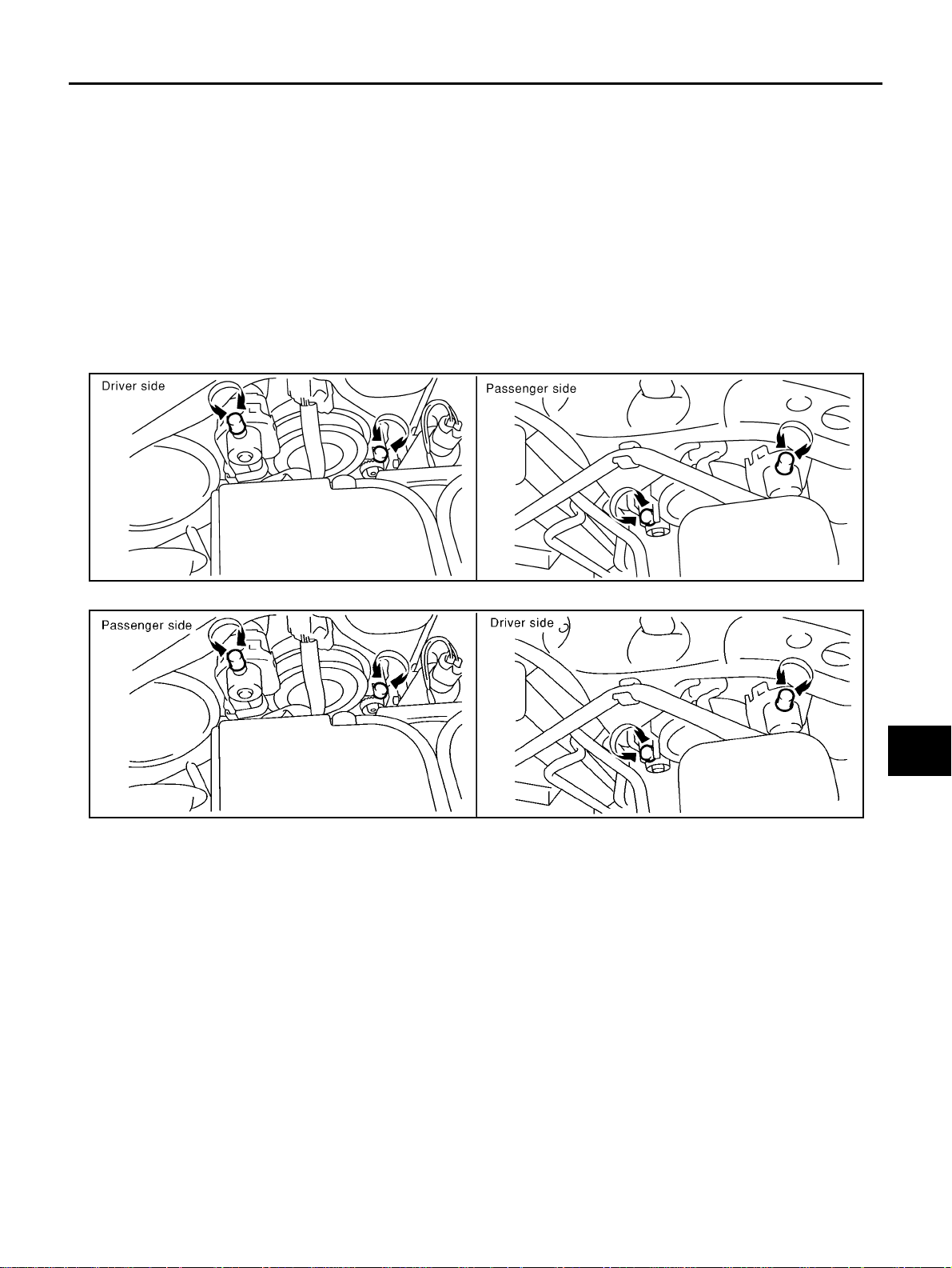
LOW BEAM
1. Turn headl amp low beam on.
LHD models
RHD models
2. Use adjusting pots to perform aiming adjustment.
● First tighten the adjusting pot all the way and then make adjustment by loosening the pot.
If the vehicle front body has been repai red and/or the headlamp assembly has been replaced, check aim-
ing. Use the aiming chart shown in the figure.
MKIA0048E
MKIA0049E
LT-16
HEADLAMP - XENON TYPE -
● Adjust headlamps so that main axis of light is parallel to cen-
ter line of body and is aligned with point P shown in illustra-
tion.
● Figure to the left shows headlamp aiming pattern for driving
on right side of road; for driving on left side of road, aiming
pattern is reversed.
● Dotted lines to point P in illustrati on show center of headlamp.
● Basic illum inating area for adjustment should be within the
range shown at left. Adjust headlamps accordingly.
Bulb Replacement
EKS004PG
CAUTION:
● After r eplacing a new xenon bulb, be sure to make aiming adjustmen ts.
● Hold only the plastic base when handling the bulb. Never touch the glass envelope.
● Do not leave headlamp reflector without bulb for a long period of time. Dust, moist ure, smoke, etc.
entering headlamp body may affect the performance of the headlamp. Remove headlamp bulb
from the headlamp reflector just before a replacement bulb is installed.
1. Disconnect negative battery cable.
2. Disconnect headlamp connector.
WARNING:
Never service a xenon headlamp with wet hands.
XENON BULB (LOW BEAM)
1. Remove washer inlet. (RH bulb)
2. Remove headlamp seal cover.
Turn bulb socket counterclockwise and unlock it.
3. Release retaining pin.
4. Remove the xenon bulb.
5. Install in the reverse orderof removal.
CAUTION:
● When disposing of the xenon bulb, do not break it;
always dispose of it as is.
● Make sure to install the bulb securely; if the xenon bulb is
improperly installed in its socket, high-ten sion cu rrent
leaks o ccur. This may lead to a melted bulb and/or bulb socket.
HIGH BEAM
1. Pull off headlamp seal cover.
“H” : Horiz ontal center line of headlamps
“W
L
”
: Distance between each h eadlamp center
“L” : 25 m (98.43 in)
“C” : 250 mm (9.84 in)
SEL254L
Headlamp (LOW) : 12V - 35W (D2R)
MKIB0118E

HEADLAMP - XENON TYPE -
LT-17
C
D
E
F
G
H
I
J
L
M
A
B
LT
2. Disconnect bulb connecto r.
3. Release retaining pin.
4. Remove the bulb.
5. Install in the reverse order of removal.
CLEARANCE LAMP, FRONT TURN SI GNAL LAMP
Refer to LT-17, "CLEARANCE LAMP, FRONT TURN SIGNAL LAMP" .
CAUTION:
● Do not touch the glass of bulb directly by hand. Keep grease and other oily matters away from it.
Do not touch bulb by hand while it is lit or right after being turned off. Burning may result.
● Do not leave bulb out of headlamp reflector for a long time because dust, moisture smoke, etc.
may affect the performance of headlamp. When replacing bulb, be sure to replace it with new one.
● When bulb is installed, be sure to lock rubber cap to ensure watertightness.
Removal and Installation
EKS004PH
REMOVAL
Refer to LT-17, "REMOVAL" .
INSTALLATION
Refer to LT-17, "INSTALLAT IO N" .
Headlamp (HIGH) : 12V - 55W (H7)

LT-18
HEADLAMP (WITH DAYTIME) - CONVENTIONAL TYPE -
HEADLAMP (WITH DAYTIME) - CONVENTIONAL TYPE -
PFP:26010
System Description
EKS004PI
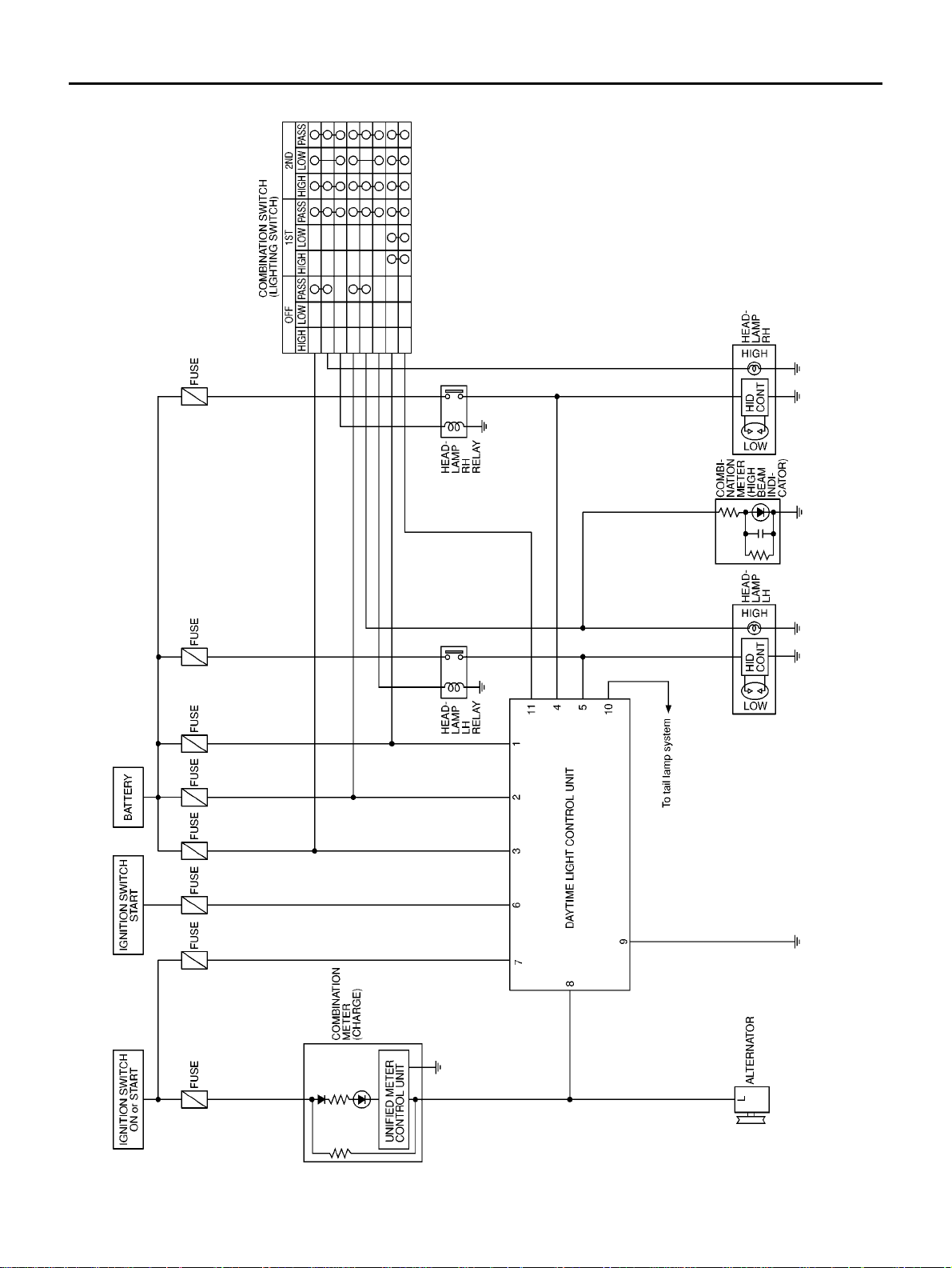
DESCRIPTION
The headlamp system for Northern Europe vehicles c ontains a daytime light control unit that activates the low
beam headlamps whenever the engine is running.
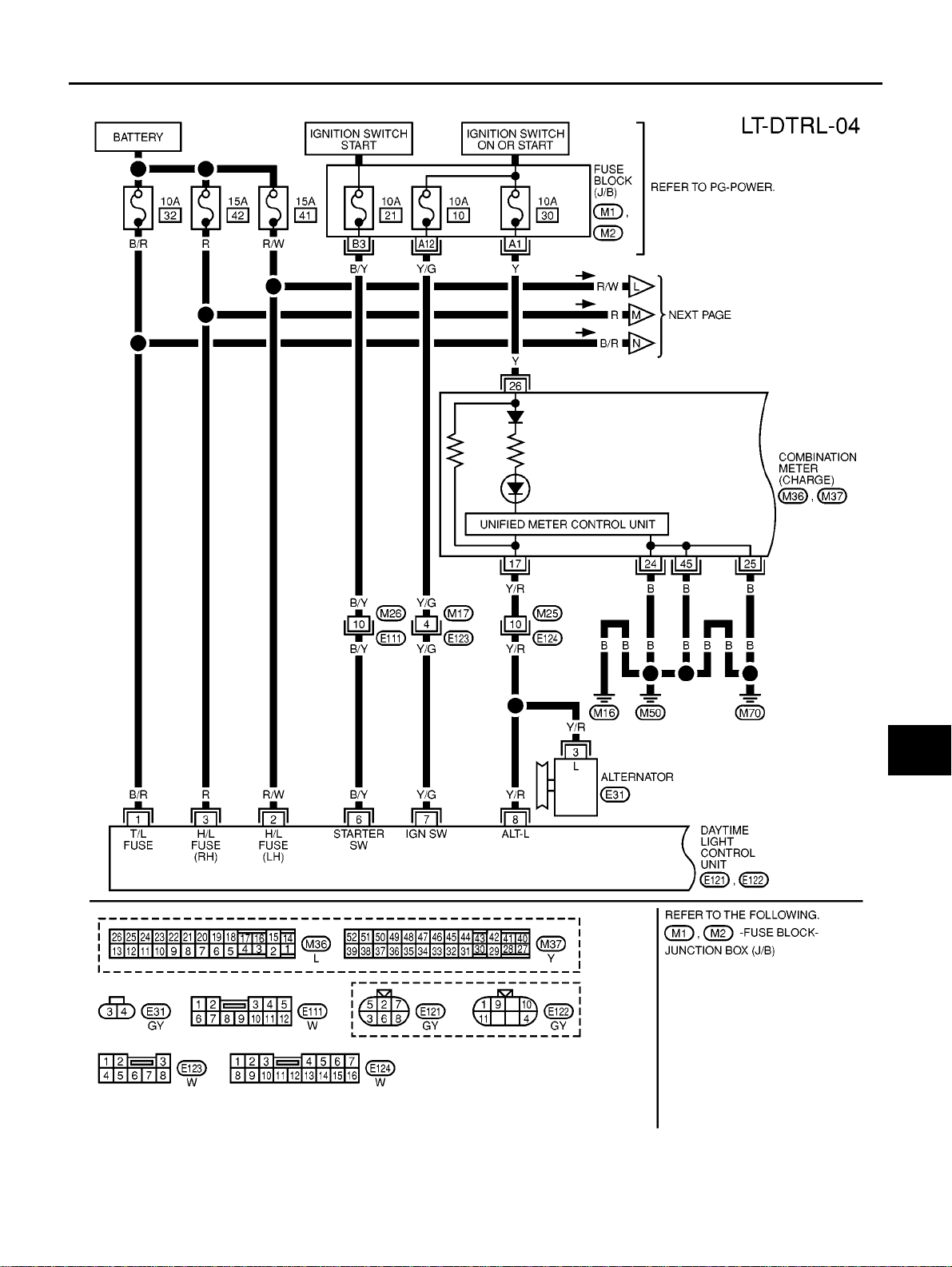
Power is supplied at all times
● to daytime light control unit terminal 1
● to lighting switch terminal 11
● through 10A (No. 32, located in the fuse and fusible link box), and
● to daytime light control unit terminal 3
● to lighting switch terminal 5
● through 15A (No. 42, located in the fuse and fusible link box), and
● to daytime light control unit terminal 2
● to lighting switch terminal 8
● through 15A (No. 41, located in the fuse and fusible link box)
Ground is supplied to daytime light control unit terminal 9 through body grounds E10, E58 and E122.
When the ignition switch is in the ON or START position, power is supplied
● to daytime light control unit terminal 7
● through 10A (No. 10, located in the fuse and fusible link box)
When the ignition switch is in the START position, power is also supplied
● to daytime light control unit terminal 6
● through 10A (No. 21, located in the fuse and fusible link box)
HEADLAMP OPERATION
For description, refer to LT-5, "System D escription"
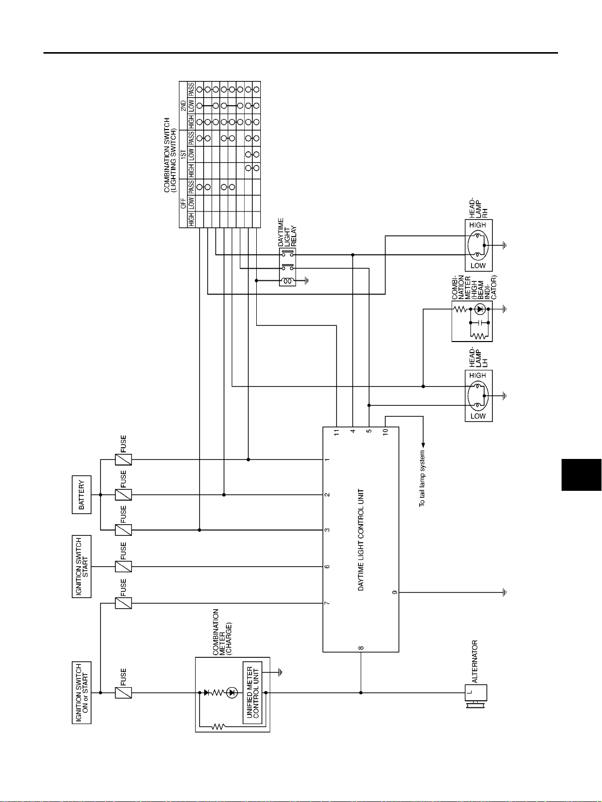
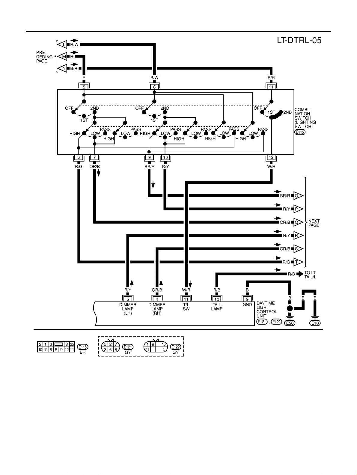
DAYTIME LIGHT OPERATION
When the engine running, the lighting switch in the OFF positi on, power is supplied
● from alternator terminal 3
● to daytime light control unit terminal 8, and
● from daytime light control unit terminal 2
● through daytime light control unit terminal 5
● to terminal of LH headlamp
● from daytime light control unit terminal 3,
● through daytime light control unit terminal 4
● to terminal of RH headlamp, and
● from daytime light control unit terminal 1
● through daytime light control unit terminal 1 0
Ground is supplied to terminal 2 of each headlamp through body grounds E10 and E58.
HEADLAMP (WITH DAYTIME) - CONVENTIONAL TYPE -
LT-19
C
D
E
F
G
H
I
J
L
M
A
B
LT
Schematic
EKS004PJ
MKWA0004E

LT-20
HEADLAMP (WITH DAYTIME) - CONVENTIONAL TYPE -
Wiring Diagram — H/LAMP —
EKS004PK
MKWA0005E
HEADLAMP (WITH DAYTIME) - CONVENTIONAL TYPE -
LT-21
C
D
E
F
G
H
I
J
L
M
A
B
LT
MKWA0006E
LT-22
HEADLAMP (WITH DAYTIME) - CONVENTIONAL TYPE -
MKWA0007E

HEADLAMP (WITH DAYTIME) - CONVENTIONAL TYPE -
LT-23
C
D
E
F
G
H
I
J
L
M
A
B
LT
Terminal and Reference Value for Daytime Light Control Unit
*: Daytime light operating: Lighting switch in “OFF” position with enginerunning.
T rouble Diagnoses
EKS004PL
Terminal
No.
Wire
color
Item Condition
Voltage
(Approximate values)
1 B/R Power source Ignition switch “OFF” Battery voltage
2 R Power source Ignitionswitch “OFF” Battery voltage
3 R/W Power source Ignition switch “OFF” Battery voltage
4 PU RH low beam
When lighting switch is turned to the 2ND position Battery voltage
When engine is running and turning lighting switch to
“OFF” (daytime light operation)
Battery voltage
5 R/Y LH low beam
When lighting switch is turned to the 2ND position Battery voltage
When engine is running and turning lighting switch to
“OFF” (daytime light operation)
Battery voltage
6 B/Y Start signal
When turning ignition switch to “START” Battery voltage
When turning ignition switch to “ON” from “START” Less than 1V
When turning ignition switch to “OFF” Less than 1V
7 Y/G Power source
When turning ignition switch to “ON” Battery voltage
When turning ignition switch to “START” Battery voltage
When turning ignition switch to “OFF” Less than 1V
8 Y/R Alternator
When turning ignition switch to “ON” Less than 1V
When engine is running Battery voltage
When turning ignition switch to “OFF” Less than 1V
9 B Ground — —
10 R/B Tail lamp
When turning ignition switch to “ON” 0V
When engine is running and turning lighting switch to
“OFF” (daytime light operation*)
Battery voltage
When turning ignition switch to “OFF” 0V
11 W/R Lightingswitch
When turning lighting switch to 1ST or 2ND Battery voltage
When turning ignition switch to “OFF” 0V
Symptom Possible cause Repairorder
LH headlamps do not operate.
1. Bulb
2.G rounds E10 and E58
3.15A fuse
4. Lighting switch
1.Check bulb.
2.Check grounds E10 and E58.
3.Check 15A fuse (No. 41, located in fuse
and fusible link box).
Verify battery positive voltage is present
at terminal 8 of lighting switch.
4.Check lighting switch.
RH headlamps do not operate.
1. Bulb
2.G rounds E10 and E58
3.15A fuse
4. Lighting switch
1.Check bulb.
2.Check grounds E10 and E58.
3.Check 15A fuse (No. 42, located in fuse
and fusible link box).
Verify battery positive voltage is present
at terminal 5 of lighting switch.
4.Check lighting switch.

LT-24
HEADLAMP (WITH DAYTIME) - CONVENTIONAL TYPE -
Aiming Adjustment
EKS004PN
Refer to LT-7, "Aiming Adjustment"
Bulb Replacement
EKS004PM
HEADLAMP
Refer to LT-9, "Bulb Replacement"
CLEARANCE LAMP, FRONT TURN SIGNAL LAMP
Refer to LT-9, "CLEARANCE LAMP, FRONT TURN SIGNA L LAMP"
LH high beam does not operate, but LH
low beam operates.
1.Bulb
2.Open in LH high beams circuit
3.Lighting switch
1.Check bulb.
2.Check continuity betweenlighting switch
terminal 9 (BR/R) and LH headlamp ter-
minal 4 (BR/R) for an open circuit.
3.Check lighting switch.
LH low beam does not operate, but LH
high beam operates.
1.Bulb
2.Open in LH low beam circuit
3.Lighting switch
1.Check bulb.
2.Check continuity betweenlighting switch
terminal 10 (R/Y) and LH headlamp ter-
minal 5 (R/Y) for an open circuit.
3.Check lighting switch.
RH high beam does not operate, butRH
low beam operates.
1.Bulb
2.Open in RH high beams circuit
3.Lighting switch
1.Check bulb.
2.Check continuity betweenlighting switch
terminal 6 (Y) and RH headlamp termi-
nal 4 (Y) for an open circuit.
3.Check lighting switch.
RH low beam does not operate, but RH
high beam operates.
1.Bulb
2.Open in RH low beam circuit
3.Lighting switch
1.Check bulb.
2.Check continuity betweenlighting switch
terminal 7 (PU) and RH headlamp termi-
nal 5 (PU) for an open circuit.
3.Check lighting switch.
High beam indicator does not work.
1.Bulb
2.Grounds M16, M50 and M70
3.Open in high beam circuit
1.Check bulb in combinationmeter.
2.Check grounds M16, M50 and M70.
3.Check continuity betweenlighting switch
terminal 9 (BR/R) and combination
meter terminal20 (BR/R) LHD or 7 (BR/
R) RHD for an open circuit.
Symptom Possible cause Repair order

HEADLAMP (WITH DAYTIME) - XENON TYPE -
LT-25
C
D
E
F
G
H
I
J
L
M
A
B
LT
HEADLAMP (WITH DAYTIME) - XENON TYPE - PFP:26010
System Description
EKS0054P
For headlamp operation, refer to LT-5, "System Description" .
For daytime operation, refer to LT-18, "
System Description" .
LT-26
HEADLAMP (WITH DAYTIME) - XENON TYPE -
Schematic
EKS004PP
MKWA0008E
HEADLAMP (WITH DAYTIME) - XENON TYPE -
LT-27
C
D
E
F
G
H
I
J
L
M
A
B
LT
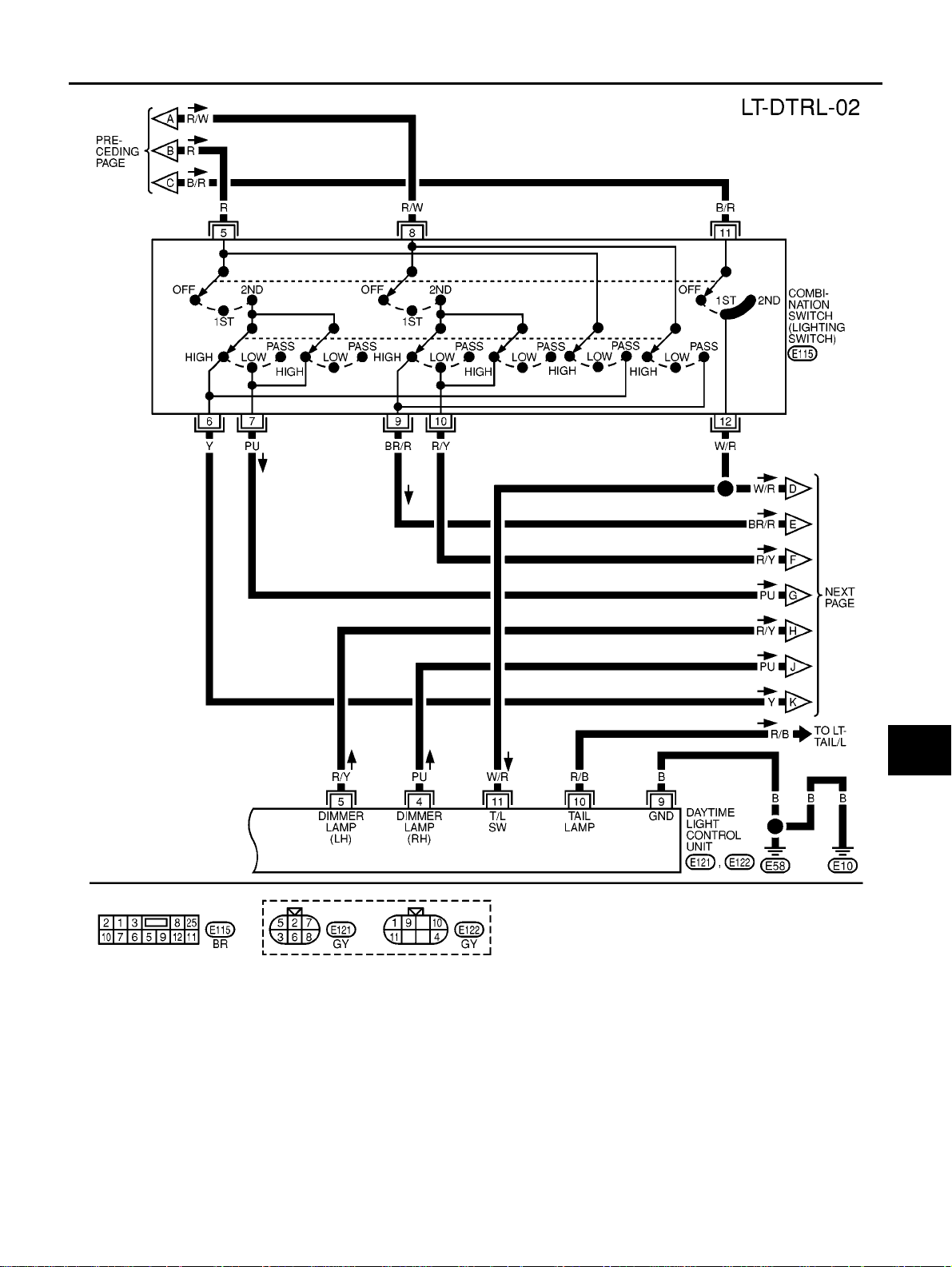
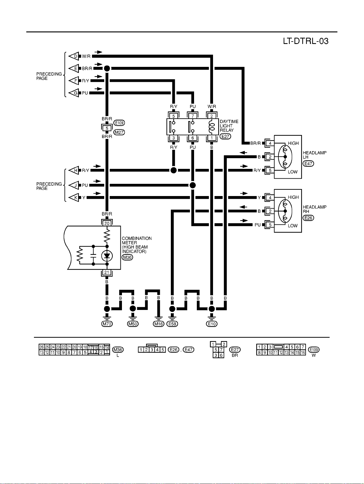
Wiring Diagram - DTRL -
EKS004PQ
MKWA0009E
LT-28
HEADLAMP (WITH DAYTIME) - XENON TYPE -
MKWA0010E

HEADLAMP (WITH DAYTIME) - XENON TYPE -
LT-29
C
D
E
F
G
H
I
J
L
M
A
B
LT
MKWA0011E

LT-30
HEADLAMP (WITH DAYTIME) - XENON TYPE -
T rouble Diagnoses
EKS004PR
DAYTIME LIGHT UNIT INSPECTION TABLE
Refer to LT-23, "Trouble Diagnoses" .
Bulb Replacement
EKS004PS
Refer to LT-16, "Bulb Replacement" .
Aiming Adjustment
EKS004PT
Refer to LT-15, "Aiming Adjustme nt" .
Loading...