


 Loading...
ENGINE CONTROL SYSTEM
SECTION EC
GI
MA
EM
LC
MODIFICATION NOTICE:
IThe SMART C/U - PREVIOUS is applicable for the 2WD models up to serial number 567231 and for the 4WD models up to serial number 584967.
IThe SMART C/U - NEW is applicable for the 2WD models from serial number 567231 and for the 4WD FE models from serial number 584967.
CL
CONTENTS
MT
TROUBLE DIAGNOSIS - INDEX .................................... |
8 |
Alphabetical & P No. Index for DTC ........................... |
8 |
PRECAUTIONS ............................................................. |
14 |
Supplemental Restraint System (SRS) ″AIR |
|
BAG″ and ″SEAT BELT PRE-TENSIONER″............. |
14 |
Precautions for On Board Diagnostic (OBD) |
|
System of Engine and A/T......................................... |
14 |
Engine Fuel & Emission Control System .................. |
15 |
Precautions ................................................................ |
16 |
Wiring Diagrams and Trouble Diagnosis................... |
17 |
PREPARATION ............................................................. |
18 |
Special Service Tools ................................................ |
18 |
Commercial Service Tools ......................................... |
18 |
ENGINE AND EMISSION CONTROL OVERALL |
|
SYSTEM......................................................................... |
20 |
Engine Control Component Parts Location............... |
20 |
Circuit Diagram .......................................................... |
24 |
System Diagram ........................................................ |
26 |
Vacuum Hose Drawing .............................................. |
27 |
System Chart ............................................................. |
28 |
ENGINE AND EMISSION BASIC CONTROL |
|
SYSTEM DESCRIPTION ............................................... |
29 |
Multiport Fuel Injection (MFI) System ....................... |
29 |
Electronic Ignition (EI) System .................................. |
31 |
Air Conditioning Cut Control...................................... |
32 |
Fuel Cut Control (at no load & high engine |
|
speed) ........................................................................ |
33 |
Evaporative Emission System ................................... |
33 |
Positive Crankcase Ventilation .................................. |
39 |
BASIC SERVICE PROCEDURE ................................... |
40 |
Fuel Pressure Release .............................................. |
40 |
Fuel Pressure Check ................................................. |
40 |
Fuel Pressure Regulator Check ................................ |
41 |
Injector ....................................................................... |
42 |
How to Check Idle Speed and Ignition Timing.......... |
43 |
Idle Speed/Ignition Timing/Idle Mixture Ratio |
|
AT |
Adjustment ................................................................. |
44 |
|
Idle Air Volume Learning ........................................... |
59 |
|
ON BOARD DIAGNOSTIC SYSTEM |
|
TF |
DESCRIPTION ............................................................... |
61 |
|
Introduction ................................................................ |
61 |
|
Two Trip Detection Logic ........................................... |
61 |
PD |
Emission-related Diagnostic Information ................... |
62 |
|
Malfunction Indicator Lamp (MIL).............................. |
76 |
AX |
OBD System Operation Chart ................................... |
77 |
|
CONSULT-II ............................................................... |
83 |
|
Generic Scan Tool (GST) .......................................... |
97 |
SU |
TROUBLE DIAGNOSIS - INTRODUCTION.................. |
99 |
|
Introduction ................................................................ |
99 |
|
Work Flow................................................................ |
101 |
BR |
TROUBLE DIAGNOSIS - BASIC INSPECTION ......... |
103 |
|
Basic Inspection....................................................... |
103 |
ST |
TROUBLE DIAGNOSIS - GENERAL |
|
|
DESCRIPTION ............................................................. |
116 |
|
DTC Inspection Priority Chart.................................. |
116 |
RS |
Fail-safe Chart ......................................................... |
117 |
|
Symptom Matrix Chart............................................. |
118 |
|
CONSULT-II Reference Value in Data Monitor |
|
BT |
Mode ........................................................................ |
122 |
|
Major Sensor Reference Graph in Data Monitor |
|
|
Mode ........................................................................ |
124 |
HA |
ECM Terminals and Reference Value ..................... |
127 |
|
TROUBLE DIAGNOSIS - SPECIFICATION VALUE .. |
136 |
SC |
Description ............................................................... |
136 |
|
Testing Condition ..................................................... |
136 |
|
Inspection Procedure............................................... |
136 |
EL |
Diagnostic Procedure .............................................. |
137 |
|
TROUBLE DIAGNOSIS FOR INTERMITTENT |
|
|
INCIDENT..................................................................... |
140 |
IDX |
Description ............................................................... |
140 |
|
Diagnostic Procedure .............................................. |
140 |
|
CONTENTS (Cont'd)
TROUBLE DIAGNOSIS FOR POWER SUPPLY........ |
141 |
ECM Terminals and Reference Value ..................... |
141 |
Main Power Supply and Ground Circuit.................. |
142 |
DTC P0100 MASS AIR FLOW SENSOR (MAFS)...... |
150 |
Component Description ........................................... |
150 |
CONSULT-II Reference Value in Data Monitor |
|
Mode ........................................................................ |
150 |
ECM Terminals and Reference Value ..................... |
150 |
On Board Diagnosis Logic....................................... |
151 |
Possible Cause........................................................ |
151 |
DTC Confirmation Procedure .................................. |
151 |
Overall Function Check ........................................... |
153 |
Wiring Diagram ........................................................ |
154 |
Diagnostic Procedure .............................................. |
155 |
DTC P0105 ABSOLUTE PRESSURE SENSOR ........ |
158 |
Component Description ........................................... |
158 |
On Board Diagnosis Logic....................................... |
158 |
DTC Confirmation Procedure .................................. |
158 |
Diagnostic Procedure .............................................. |
159 |
DTC P0110 INTAKE AIR TEMPERATURE |
|
SENSOR ...................................................................... |
160 |
Component Description ........................................... |
160 |
On Board Diagnosis Logic....................................... |
160 |
Possible Cause........................................................ |
160 |
DTC Confirmation Procedure .................................. |
160 |
Wiring Diagram ........................................................ |
162 |
Diagnostic Procedure .............................................. |
163 |
DTC P0115 ENGINE COOLANT TEMPERATURE |
|
SENSOR (ECTS) (CIRCUIT) ....................................... |
165 |
Component Description ........................................... |
165 |
On Board Diagnosis Logic....................................... |
165 |
Possible Cause........................................................ |
166 |
DTC Confirmation Procedure .................................. |
166 |
Wiring Diagram ........................................................ |
167 |
Diagnostic Procedure .............................................. |
168 |
DTC P0120 THROTTLE POSITION SENSOR ........... |
170 |
Description ............................................................... |
170 |
CONSULT-II Reference Value in Data Monitor |
|
Mode ........................................................................ |
170 |
ECM Terminals and Reference Value ..................... |
171 |
On Board Diagnosis Logic....................................... |
171 |
Possible Cause........................................................ |
171 |
DTC Confirmation Procedure .................................. |
172 |
Wiring Diagram ........................................................ |
176 |
Diagnostic Procedure .............................................. |
177 |
DTC P0125 ENGINE COOLANT TEMPERATURE |
|
SENSOR (ECTS) ......................................................... |
182 |
Description ............................................................... |
182 |
On Board Diagnosis Logic....................................... |
182 |
Possible Cause........................................................ |
183 |
DTC Confirmation Procedure .................................. |
183 |
Wiring Diagram ........................................................ |
184 |
Diagnostic Procedure .............................................. |
185 |
DTC P0130, P0150 HEATED OXYGEN SENSOR 1 |
|
(FRONT) (BANK 1)/(BANK 2) (CIRCUIT) .................. |
187 |
Component Description ........................................... |
187 |
CONSULT-II Reference Value in Data Monitor |
|
Mode ........................................................................ |
187 |
ECM Terminals and Reference Value ..................... |
187 |
On Board Diagnosis Logic....................................... |
188 |
Possible Cause........................................................ |
188 |
DTC Confirmation Procedure .................................. |
189 |
Overall Function Check ........................................... |
189 |
Wiring Diagram ........................................................ |
191 |
Diagnostic Procedure .............................................. |
193 |
DTC P0131, P0151 HEATED OXYGEN SENSOR 1 |
|
(FRONT) (BANK 1)/(BANK 2) (LEAN SHIFT |
|
MONITORING) ............................................................. |
197 |
Component Description ........................................... |
197 |
CONSULT-II Reference Value in Data Monitor |
|
Mode ........................................................................ |
197 |
ECM Terminals and Reference Value ..................... |
197 |
On Board Diagnosis Logic....................................... |
198 |
Possible Cause........................................................ |
198 |
DTC Confirmation Procedure .................................. |
198 |
Overall Function Check ........................................... |
199 |
Diagnostic Procedure .............................................. |
200 |
DTC P0132, P0152 HEATED OXYGEN SENSOR 1 |
|
(FRONT) (BANK 1)/(BANK 2) (RICH SHIFT |
|
MONITORING) ............................................................. |
205 |
Component Description ........................................... |
205 |
CONSULT-II Reference Value in Data Monitor |
|
Mode ........................................................................ |
205 |
ECM Terminals and Reference Value ..................... |
205 |
On Board Diagnosis Logic....................................... |
206 |
Possible Cause........................................................ |
206 |
DTC Confirmation Procedure .................................. |
206 |
Overall Function Check ........................................... |
207 |
Diagnostic Procedure .............................................. |
208 |
DTC P0133, P0153 HEATED OXYGEN SENSOR 1 |
|
(FRONT) (BANK 1)/(BANK 2) (RESPONSE |
|
MONITORING) ............................................................. |
213 |
Component Description ........................................... |
213 |
CONSULT-II Reference Value in Data Monitor |
|
Mode ........................................................................ |
213 |
ECM Terminals and Reference Value ..................... |
213 |
On Board Diagnosis Logic....................................... |
214 |
Possible Cause........................................................ |
214 |
DTC Confirmation Procedure .................................. |
215 |
Overall Function Check ........................................... |
216 |
Wiring Diagram ........................................................ |
217 |
Diagnostic Procedure .............................................. |
219 |
DTC P0134, P0154 HEATED OXYGEN SENSOR 1 |
|
(FRONT) (BANK 1)/(BANK 2) (HIGH VOLTAGE)...... |
226 |
EC-2

CONTENTS (Cont'd) |
GI |
Component Description ........................................... |
226 |
CONSULT-II Reference Value in Data Monitor |
|
Mode ........................................................................ |
226 |
ECM Terminals and Reference Value ..................... |
226 |
On Board Diagnosis Logic....................................... |
227 |
Possible Cause........................................................ |
227 |
DTC Confirmation Procedure .................................. |
227 |
Wiring Diagram ........................................................ |
229 |
Diagnostic Procedure .............................................. |
231 |
DTC P0135, P0155 HEATED OXYGEN SENSOR 1 |
|
HEATER (FRONT) (BANK 1)/(BANK 2)..................... |
235 |
Description ............................................................... |
235 |
CONSULT-II Reference Value in Data Monitor |
|
Mode ........................................................................ |
235 |
ECM Terminals and Reference Value ..................... |
235 |
On Board Diagnosis Logic....................................... |
236 |
Possible Cause........................................................ |
236 |
DTC Confirmation Procedure .................................. |
236 |
Wiring Diagram ........................................................ |
237 |
Diagnostic Procedure .............................................. |
239 |
DTC P0137, P0157 HEATED OXYGEN SENSOR 2 |
|
(REAR) (BANK 1)/(BANK 2) (MIN. VOLTAGE |
|
MONITORING) ............................................................. |
242 |
Component Description ........................................... |
242 |
CONSULT-II Reference Value in Data Monitor |
|
Mode ........................................................................ |
242 |
ECM Terminals and Reference Value ..................... |
242 |
On Board Diagnosis Logic....................................... |
242 |
Possible Cause........................................................ |
243 |
DTC Confirmation Procedure .................................. |
243 |
Overall Function Check ........................................... |
243 |
Wiring Diagram ........................................................ |
245 |
Diagnostic Procedure .............................................. |
247 |
DTC P0138, P0158 HEATED OXYGEN SENSOR 2 |
|
(REAR) (BANK 1)/(BANK 2) (MAX. VOLTAGE |
|
MONITORING) ............................................................. |
252 |
Component Description ........................................... |
252 |
CONSULT-II Reference Value in Data Monitor |
|
Mode ........................................................................ |
252 |
ECM Terminals and Reference Value ..................... |
252 |
On Board Diagnosis Logic....................................... |
252 |
Possible Cause........................................................ |
253 |
DTC Confirmation Procedure .................................. |
253 |
Overall Function Check ........................................... |
253 |
Wiring Diagram ........................................................ |
255 |
Diagnostic Procedure .............................................. |
257 |
DTC P0139, P0159 HEATED OXYGEN SENSOR 2 |
|
(REAR) (BANK 1)/(BANK 2) (RESPONSE |
|
MONITORING) ............................................................. |
262 |
Component Description ........................................... |
262 |
CONSULT-II Reference Value in Data Monitor |
|
Mode ........................................................................ |
262 |
ECM Terminals and Reference Value ..................... |
262 |
MA |
On Board Diagnosis Logic....................................... |
262 |
|
Possible Cause........................................................ |
263 |
|
DTC Confirmation Procedure .................................. |
263 |
EM |
Overall Function Check ........................................... |
263 |
|
Wiring Diagram ........................................................ |
265 |
|
Diagnostic Procedure .............................................. |
267 |
LC |
DTC P0140, P0160 HEATED OXYGEN SENSOR 2 |
|
|
(REAR) (BANK 1)/(BANK 2) (HIGH VOLTAGE)........ |
272 |
|
Component Description ........................................... |
272 |
|
CONSULT-II Reference Value in Data Monitor |
|
|
Mode ........................................................................ |
272 |
FE |
ECM Terminals and Reference Value ..................... |
272 |
|
On Board Diagnosis Logic....................................... |
272 |
|
Possible Cause........................................................ |
273 |
CL |
DTC Confirmation Procedure .................................. |
273 |
|
Overall Function Check ........................................... |
273 |
|
Wiring Diagram ........................................................ |
275 |
MT |
Diagnostic Procedure .............................................. |
277 |
|
DTC P0141, P0161 HEATED OXYGEN SENSOR 2 |
|
AT |
HEATER (REAR) (BANK 1)/(BANK 2)....................... |
281 |
|
Description ............................................................... |
281 |
|
CONSULT-II Reference Value in Data Monitor |
|
TF |
Mode ........................................................................ |
281 |
|
ECM Terminals and Reference Value ..................... |
281 |
|
On Board Diagnosis Logic....................................... |
282 |
PD |
Possible Cause........................................................ |
282 |
|
DTC Confirmation Procedure .................................. |
282 |
AX |
Wiring Diagram ........................................................ |
284 |
|
Diagnostic Procedure .............................................. |
286 |
|
DTC P0171 (RIGHT, -B1), P0174 (LEFT, -B2) |
|
SU |
FUEL INJECTION SYSTEM FUNCTION (LEAN)....... |
289 |
|
On Board Diagnosis Logic....................................... |
289 |
|
Possible Cause........................................................ |
289 |
BR |
DTC Confirmation Procedure .................................. |
289 |
|
Wiring Diagram ........................................................ |
291 |
|
Diagnostic Procedure .............................................. |
293 |
ST |
DTC P0172 (RIGHT, -B1), P0175 (LEFT, -B2) |
|
|
FUEL INJECTION SYSTEM FUNCTION (RICH)........ |
297 |
RS |
On Board Diagnosis Logic....................................... |
297 |
|
Possible Cause........................................................ |
297 |
|
DTC Confirmation Procedure .................................. |
297 |
BT |
Wiring Diagram ........................................................ |
299 |
|
Diagnostic Procedure .............................................. |
301 |
|
DTC P0180 FUEL TANK TEMPERATURE |
304 |
HA |
SENSOR ...................................................................... |
|
|
Component Description ........................................... |
304 |
SC |
On Board Diagnosis Logic....................................... |
304 |
|
Possible Cause........................................................ |
304 |
|
DTC Confirmation Procedure .................................. |
305 |
EL |
Wiring Diagram ........................................................ |
306 |
|
Diagnostic Procedure .............................................. |
307 |
|
IDX
EC-3
CONTENTS (Cont'd)
DTC P0217 COOLANT OVERTEMPERATURE |
|
ENRICHMENT PROTECTION..................................... |
309 |
On Board Diagnosis Logic....................................... |
309 |
Possible Cause........................................................ |
309 |
Overall Function Check ........................................... |
309 |
Diagnostic Procedure .............................................. |
311 |
Main 12 Causes of Overheating.............................. |
314 |
DTC P0300 - P0306 NO. 6 - 1 CYLINDER |
|
MISFIRE, MULTIPLE CYLINDER MISFIRE ............... |
315 |
On Board Diagnosis Logic....................................... |
315 |
Possible Cause........................................................ |
315 |
DTC Confirmation Procedure .................................. |
316 |
Diagnostic Procedure .............................................. |
316 |
DTC P0325 KNOCK SENSOR (KS) ........................... |
323 |
Component Description ........................................... |
323 |
ECM Terminals and Reference Value ..................... |
323 |
On Board Diagnosis Logic....................................... |
323 |
Possible Cause........................................................ |
323 |
DTC Confirmation Procedure .................................. |
323 |
Wiring Diagram ........................................................ |
325 |
Diagnostic Procedure .............................................. |
326 |
DTC P0335 CRANKSHAFT POSITION SENSOR |
|
(CKPS) (POS) .............................................................. |
329 |
Component Description ........................................... |
329 |
CONSULT-II Reference Value in Data Monitor |
|
Mode ........................................................................ |
329 |
ECM Terminals and Reference Value ..................... |
330 |
On Board Diagnosis Logic....................................... |
330 |
Possible Cause........................................................ |
330 |
DTC Confirmation Procedure .................................. |
331 |
Wiring Diagram ........................................................ |
332 |
Diagnostic Procedure .............................................. |
333 |
DTC P0340 CAMSHAFT POSITION SENSOR |
|
(CMPS) (PHASE)......................................................... |
337 |
Component Description ........................................... |
337 |
ECM Terminals and Reference Value ..................... |
337 |
On Board Diagnosis Logic....................................... |
337 |
Possible Cause........................................................ |
338 |
DTC Confirmation Procedure .................................. |
338 |
Wiring Diagram ........................................................ |
339 |
Diagnostic Procedure .............................................. |
340 |
DTC P0420 (RIGHT BANK, -B1), P0430 (LEFT |
|
BANK, -B2) THREE WAY CATALYST FUNCTION ... |
342 |
On Board Diagnosis Logic....................................... |
342 |
Possible Cause........................................................ |
342 |
DTC Confirmation Procedure .................................. |
343 |
Overall Function Check ........................................... |
343 |
Diagnostic Procedure .............................................. |
344 |
DTC P0440 EVAP CONTROL SYSTEM (SMALL |
|
LEAK) (NEGATIVE PRESSURE)................................ |
347 |
On Board Diagnosis Logic....................................... |
347 |
Possible Cause........................................................ |
347 |
DTC Confirmation Procedure .................................. |
349 |
Diagnostic Procedure .............................................. |
350 |
DTC P0443 EVAP CANISTER PURGE VOLUME |
|
CONTROL SOLENOID VALVE (CIRCUIT)................. |
362 |
Description ............................................................... |
362 |
CONSULT-II Reference Value in Data Monitor |
|
Mode ........................................................................ |
362 |
ECM Terminals and Reference Value ..................... |
363 |
On Board Diagnosis Logic....................................... |
363 |
Possible Cause........................................................ |
363 |
DTC Confirmation Procedure .................................. |
364 |
Wiring Diagram ........................................................ |
365 |
Diagnostic Procedure .............................................. |
366 |
DTC P0446 EVAPORATIVE EMISSION (EVAP) |
|
CANISTER VENT CONTROL VALVE (CIRCUIT) ...... |
369 |
Component Description ........................................... |
369 |
CONSULT-II Reference Value in Data Monitor |
|
Mode ........................................................................ |
369 |
ECM Terminals and Reference Value ..................... |
369 |
On Board Diagnosis Logic....................................... |
369 |
Possible Cause........................................................ |
370 |
DTC Confirmation Procedure .................................. |
370 |
Wiring Diagram ........................................................ |
371 |
Diagnostic Procedure .............................................. |
372 |
DTC P0450 EVAPORATIVE EMISSION (EVAP) |
|
CONTROL SYSTEM PRESSURE SENSOR .............. |
376 |
Component Description ........................................... |
376 |
CONSULT-II Reference Value in Data Monitor |
|
Mode ........................................................................ |
376 |
ECM Terminals and Reference Value ..................... |
376 |
On Board Diagnosis Logic....................................... |
377 |
Possible Cause........................................................ |
377 |
DTC Confirmation Procedure .................................. |
377 |
Wiring Diagram ........................................................ |
379 |
Diagnostic Procedure .............................................. |
380 |
DTC P0455 EVAP CONTROL SYSTEM (GROSS |
|
LEAK)........................................................................... |
389 |
On Board Diagnosis Logic....................................... |
389 |
Possible Cause........................................................ |
389 |
DTC Confirmation Procedure .................................. |
391 |
Diagnostic Procedure .............................................. |
392 |
DTC P0460 FUEL LEVEL SENSOR FUNCTION |
|
(SLOSH)....................................................................... |
402 |
Component Description ........................................... |
402 |
On Board Diagnostic Logic...................................... |
402 |
Possible Cause........................................................ |
402 |
DTC Confirmation Procedure .................................. |
402 |
Wiring Diagram ........................................................ |
403 |
Diagnostic Procedure .............................................. |
404 |
DTC P0461 FUEL LEVEL SENSOR FUNCTION ....... |
406 |
Component Description ........................................... |
406 |
On Board Diagnostic Logic...................................... |
406 |
EC-4

CONTENTS (Cont'd) |
GI |
Possible Cause........................................................ |
406 |
Overall Function Check ........................................... |
406 |
DTC P0464 FUEL LEVEL SENSOR CIRCUIT ........... |
408 |
Component Description ........................................... |
408 |
On Board Diagnostic Logic...................................... |
408 |
Possible Cause........................................................ |
408 |
DTC Confirmation Procedure .................................. |
408 |
Wiring Diagram ........................................................ |
409 |
Diagnostic Procedure .............................................. |
410 |
DTC P0500 VEHICLE SPEED SENSOR (VSS) ......... |
412 |
Component Description ........................................... |
412 |
ECM Terminals and Reference Value ..................... |
412 |
On Board Diagnosis Logic....................................... |
412 |
Possible Cause........................................................ |
413 |
DTC Confirmation Procedure .................................. |
413 |
Overall Function Check ........................................... |
414 |
Wiring Diagram ........................................................ |
415 |
Diagnostic Procedure .............................................. |
416 |
DTC P0505 IDLE AIR CONTROL VALVE (IACV) - |
|
AUXILIARY AIR CONTROL (AAC) VALVE ............... |
417 |
Description ............................................................... |
417 |
CONSULT-II Reference Value in Data Monitor |
|
Mode ........................................................................ |
418 |
ECM Terminals and Reference Value ..................... |
418 |
On Board Diagnosis Logic....................................... |
418 |
Possible Cause........................................................ |
418 |
DTC Confirmation Procedure .................................. |
418 |
Wiring Diagram ........................................................ |
420 |
Diagnostic Procedure .............................................. |
421 |
DTC P0510 CLOSED THROTTLE POSITION |
|
SWITCH ....................................................................... |
426 |
Component Description ........................................... |
426 |
CONSULT-II Reference Value in Data Monitor |
|
Mode ........................................................................ |
426 |
ECM Terminals and Reference Value ..................... |
426 |
On Board Diagnosis Logic....................................... |
426 |
Possible Cause........................................................ |
426 |
DTC Confirmation Procedure .................................. |
427 |
Overall Function Check ........................................... |
427 |
Wiring Diagram ........................................................ |
429 |
Diagnostic Procedure .............................................. |
430 |
DTC P0600 A/T COMMUNICATION LINE.................. |
434 |
System Description.................................................. |
434 |
ECM Terminals and Reference Value ..................... |
434 |
On Board Diagnosis Logic....................................... |
434 |
Possible Cause........................................................ |
434 |
DTC Confirmation Procedure .................................. |
434 |
Wiring Diagram ........................................................ |
436 |
Diagnostic Procedure .............................................. |
437 |
DTC P0605 ECM ......................................................... |
438 |
Component Description ........................................... |
438 |
On Board Diagnosis Logic....................................... |
438 |
Possible Cause........................................................ |
438 |
MA |
DTC Confirmation Procedure .................................. |
438 |
|
Diagnostic Procedure .............................................. |
439 |
|
DTC P1110 (RIGHT, -B1), P1135 (LEFT, -B2) |
|
EM |
INTAKE VALVE TIMING CONTROL .......................... |
440 |
|
Description ............................................................... |
440 |
|
CONSULT-II Reference Value in Data Monitor |
|
LC |
Mode ........................................................................ |
440 |
|
ECM Terminals and Reference Value ..................... |
441 |
|
On Board Diagnosis Logic....................................... |
442 |
|
Possible Cause........................................................ |
442 |
|
DTC Confirmation Procedure .................................. |
443 |
FE |
DTC P1111 (RIGHT, -B1), P1136 (LEFT, -B2) |
|
|
INTAKE VALVE TIMING CONTROL SOLENOID |
|
|
VALVE (CIRCUIT)........................................................ |
445 |
CL |
Component Description ........................................... |
445 |
|
CONSULT-II Reference Value in Data Monitor |
|
|
Mode ........................................................................ |
445 |
MT |
ECM Terminals and Reference Value ..................... |
445 |
|
On Board Diagnosis Logic....................................... |
446 |
AT |
Possible Cause........................................................ |
446 |
|
DTC Confirmation Procedure .................................. |
446 |
|
Wiring Diagram ........................................................ |
447 |
TF |
Diagnostic Procedure .............................................. |
449 |
|
DTC P1130 SWIRL CONTROL VALVE CONTROL |
|
|
SOLENOID VALVE...................................................... |
452 |
PD |
Description ............................................................... |
452 |
|
CONSULT-II Reference Value in Data Monitor |
|
AX |
Mode ........................................................................ |
453 |
|
ECM Terminals and Reference Value ..................... |
453 |
|
On Board Diagnosis Logic....................................... |
453 |
SU |
Possible Cause........................................................ |
454 |
|
DTC Confirmation Procedure .................................. |
454 |
|
Wiring Diagram ........................................................ |
456 |
BR |
Diagnostic Procedure .............................................. |
457 |
|
DTC P1140 (RIGHT, -B1), P1145 (LEFT, -B2) |
|
|
INTAKE VALVE TIMING CONTROL POSITION |
|
ST |
SENSOR (CIRCUIT) .................................................... |
475 |
|
Component Description ........................................... |
475 |
RS |
CONSULT-II Reference Value in Data Monitor |
|
|
Mode ........................................................................ |
475 |
|
ECM Terminals and Reference Value ..................... |
476 |
BT |
On Board Diagnosis Logic....................................... |
476 |
|
Possible Cause........................................................ |
477 |
|
DTC Confirmation Procedure .................................. |
477 |
HA |
Wiring Diagram ........................................................ |
478 |
|
Diagnostic Procedure .............................................. |
480 |
SC |
DTC P1148 (RIGHT BANK, -B1), P1168 (LEFT |
|
|
BANK, -B2) CLOSED LOOP CONTROL ................... |
484 |
|
On Board Diagnosis Logic....................................... |
484 |
EL |
Possible Cause........................................................ |
484 |
|
DTC Confirmation Procedure .................................. |
484 |
|
IDX
EC-5
CONTENTS (Cont'd)
Overall Function Check ........................................... |
485 |
Diagnostic Procedure .............................................. |
485 |
DTC P1165 SWIRL CONTROL VALVE CONTROL |
|
VACUUM CHECK SWITCH......................................... |
486 |
Component Description ........................................... |
486 |
CONSULT-II Reference Value in Data Monitor |
|
Mode ........................................................................ |
486 |
ECM Terminals and Reference Value ..................... |
486 |
On Board Diagnosis Logic....................................... |
487 |
Possible Cause........................................................ |
487 |
DTC Confirmation Procedure .................................. |
487 |
Wiring Diagram ........................................................ |
488 |
Diagnostic Procedure .............................................. |
489 |
DTC P1320 IGNITION SIGNAL................................... |
492 |
Component Description ........................................... |
492 |
ECM Terminals and Reference Value ..................... |
492 |
On Board Diagnosis Logic....................................... |
492 |
Possible Cause........................................................ |
493 |
DTC Confirmation Procedure .................................. |
493 |
Wiring Diagram ........................................................ |
494 |
Diagnostic Procedure .............................................. |
497 |
DTC P1335 CRANKSHAFT POSITION SENSOR |
|
(CKPS) (REF) .............................................................. |
503 |
Component Description ........................................... |
503 |
CONSULT-II Reference Value in Data Monitor |
|
Mode ........................................................................ |
503 |
ECM Terminals and Reference Value ..................... |
503 |
On Board Diagnosis Logic....................................... |
504 |
Possible Cause........................................................ |
504 |
DTC Confirmation Procedure .................................. |
504 |
Wiring Diagram ........................................................ |
506 |
Diagnostic Procedure .............................................. |
507 |
DTC P1336 CRANKSHAFT POSITION SENSOR |
|
(CKPS) (POS) (COG) .................................................. |
510 |
Component Description ........................................... |
510 |
CONSULT-II Reference Value in Data Monitor |
|
Mode ........................................................................ |
510 |
ECM Terminals and Reference Value ..................... |
511 |
On Board Diagnosis Logic....................................... |
511 |
Possible Cause........................................................ |
511 |
DTC Confirmation Procedure .................................. |
512 |
Wiring Diagram ........................................................ |
513 |
Diagnostic Procedure .............................................. |
514 |
DTC P1441 EVAP CONTROL SYSTEM (VERY |
|
SMALL LEAK) ............................................................. |
519 |
On Board Diagnosis Logic....................................... |
519 |
Possible Cause........................................................ |
519 |
DTC Confirmation Procedure .................................. |
520 |
Diagnostic Procedure .............................................. |
522 |
DTC P1444 EVAP CANISTER PURGE VOLUME |
|
CONTROL SOLENOID VALVE................................... |
534 |
Description ............................................................... |
534 |
CONSULT-II Reference Value in Data Monitor |
|
Mode ........................................................................ |
534 |
ECM Terminals and Reference Value ..................... |
535 |
On Board Diagnosis Logic....................................... |
535 |
Possible Cause........................................................ |
535 |
DTC Confirmation Procedure .................................. |
536 |
Wiring Diagram ........................................................ |
537 |
Diagnostic Procedure .............................................. |
538 |
DTC P1446 EVAPORATIVE EMISSION (EVAP) |
|
CANISTER VENT CONTROL VALVE (CLOSE)......... |
546 |
Component Description ........................................... |
546 |
CONSULT-II Reference Value in Data Monitor |
|
Mode ........................................................................ |
546 |
ECM Terminals and Reference Value ..................... |
546 |
On Board Diagnosis Logic....................................... |
546 |
Possible Cause........................................................ |
547 |
DTC Confirmation Procedure .................................. |
547 |
Wiring Diagram ........................................................ |
548 |
Diagnostic Procedure .............................................. |
549 |
DTC P1447 EVAPORATIVE EMISSION (EVAP) |
|
CONTROL SYSTEM PURGE FLOW |
|
MONITORING .............................................................. |
554 |
System Description.................................................. |
554 |
On Board Diagnosis Logic....................................... |
554 |
Possible Cause........................................................ |
554 |
DTC Confirmation Procedure .................................. |
555 |
Overall Function Check ........................................... |
556 |
Diagnostic Procedure .............................................. |
557 |
DTC P1448 EVAPORATIVE EMISSION (EVAP) |
|
CANISTER VENT CONTROL VALVE (OPEN)........... |
565 |
Component Description ........................................... |
565 |
CONSULT-II Reference Value in Data Monitor |
|
Mode ........................................................................ |
565 |
ECM Terminals and Reference Value ..................... |
565 |
On Board Diagnosis Logic....................................... |
565 |
Possible Cause........................................................ |
566 |
DTC Confirmation Procedure .................................. |
566 |
Overall Function Check ........................................... |
567 |
Wiring Diagram ........................................................ |
568 |
Diagnostic Procedure .............................................. |
569 |
DTC P1464 FUEL LEVEL SENSOR CIRCUIT |
|
(GROUND SIGNAL) .................................................... |
574 |
Component Description ........................................... |
574 |
On Board Diagnostic Logic...................................... |
574 |
Possible Cause........................................................ |
574 |
DTC Confirmation Procedure .................................. |
574 |
Wiring Diagram ........................................................ |
575 |
Diagnostic Procedure .............................................. |
576 |
DTC P1490 VACUUM CUT VALVE BYPASS |
|
VALVE (CIRCUIT)........................................................ |
577 |
Description ............................................................... |
577 |
EC-6

CONTENTS (Cont'd)
CONSULT-II Reference Value in Data Monitor |
|
Mode ........................................................................ |
577 |
ECM Terminals and Reference Value ..................... |
577 |
On Board Diagnosis Logic....................................... |
578 |
Possible Cause........................................................ |
578 |
DTC Confirmation Procedure .................................. |
578 |
Wiring Diagram ........................................................ |
579 |
Diagnostic Procedure .............................................. |
580 |
DTC P1491 VACUUM CUT VALVE BYPASS |
|
VALVE.......................................................................... |
583 |
Description ............................................................... |
583 |
CONSULT-II Reference Value in Data Monitor |
|
Mode ........................................................................ |
583 |
ECM Terminals and Reference Value ..................... |
583 |
On Board Diagnosis Logic....................................... |
584 |
Possible Cause........................................................ |
584 |
DTC Confirmation Procedure .................................. |
584 |
Overall Function Check ........................................... |
585 |
Wiring Diagram ........................................................ |
586 |
Diagnostic Procedure .............................................. |
587 |
DTC P1605 A/T DIAGNOSIS COMMUNICATION |
|
LINE ............................................................................. |
595 |
Component Description ........................................... |
595 |
On Board Diagnosis Logic....................................... |
595 |
Possible Cause........................................................ |
595 |
DTC Confirmation Procedure .................................. |
595 |
DTC P1706 PARK/NEUTRAL POSITION (PNP) |
|
SWITCH ....................................................................... |
596 |
Component Description ........................................... |
596 |
CONSULT-II Reference Value in Data Monitor |
|
Mode ........................................................................ |
596 |
ECM Terminals and Reference Value ..................... |
596 |
On Board Diagnosis Logic....................................... |
596 |
Possible Cause........................................................ |
596 |
DTC Confirmation Procedure .................................. |
597 |
Overall Function Check ........................................... |
598 |
Wiring Diagram ........................................................ |
599 |
Diagnostic Procedure .............................................. |
600 |
VARIABLE INDUCTION AIR CONTROL SYSTEM |
|
(VIAS)........................................................................... |
603 |
Description ............................................................... |
603 |
ECM Terminals and Reference Value ..................... |
604 |
Wiring Diagram ........................................................ |
605 |
Diagnostic Procedure .............................................. |
606 |
INJECTOR ................................................................... |
609 |
Component Description ........................................... |
609 |
CONSULT-II Reference Value in Data Monitor |
|
Mode ........................................................................ |
609 |
ECM Terminals and Reference Value ..................... |
609 |
Wiring Diagram ........................................................ |
610 |
Diagnostic Procedure .............................................. |
611 |
START SIGNAL........................................................... |
614 |
CONSULT-II Reference Value in Data Monitor |
|
Mode ........................................................................ |
614 |
ECM Terminals and Reference Value ..................... |
614 |
Wiring Diagram ........................................................ |
615 |
Diagnostic Procedure .............................................. |
616 |
FUEL PUMP................................................................. |
618 |
System Description.................................................. |
618 |
Component Description ........................................... |
618 |
CONSULT-II Reference Value in Data Monitor |
|
Mode ........................................................................ |
618 |
ECM Terminals and Reference Value ..................... |
619 |
Wiring Diagram ........................................................ |
620 |
Diagnostic Procedure .............................................. |
621 |
POWER STEERING OIL PRESSURE SWITCH......... |
627 |
Component Description ........................................... |
627 |
CONSULT-II Reference Value in Data Monitor |
|
Mode ........................................................................ |
627 |
ECM Terminals and Reference Value ..................... |
627 |
Wiring Diagram ........................................................ |
628 |
Diagnostic Procedure .............................................. |
629 |
REFRIGERANT PRESSURE SENSOR ...................... |
632 |
Description ............................................................... |
632 |
ECM Terminals and Reference Value ..................... |
632 |
Wiring Diagram ........................................................ |
633 |
Diagnostic Procedure .............................................. |
634 |
ELECTRICAL LOAD SIGNAL..................................... |
636 |
ECM Terminals and Reference Value ..................... |
636 |
Wiring Diagram ........................................................ |
637 |
Diagnostic Procedure .............................................. |
639 |
MIL & DATA LINK CONNECTORS ............................ |
642 |
Wiring Diagram ........................................................ |
642 |
SERVICE DATA AND SPECIFICATIONS (SDS) ....... |
643 |
Fuel Pressure Regulator.......................................... |
643 |
Idle Speed and Ignition Timing................................ |
643 |
Mass Air Flow Sensor.............................................. |
643 |
Engine Coolant Temperature Sensor ...................... |
643 |
Heated Oxygen Sensor 1 Heater (front) ................. |
643 |
Fuel Pump ............................................................... |
643 |
IACV-AAC Valve ...................................................... |
643 |
Injector ..................................................................... |
643 |
Resistor.................................................................... |
643 |
Throttle Position Sensor .......................................... |
644 |
Calculated Load Value............................................. |
644 |
Intake Air Temperature Sensor................................ |
644 |
Heated Oxygen Sensor 2 Heater (rear) .................. |
644 |
Crankshaft Position Sensor (REF) .......................... |
644 |
Fuel Tank Temperature Sensor ............................... |
644 |
Camshaft Position Sensor (PHASE) ....................... |
644 |
GI
MA
EM
LC
FE
CL
MT
AT
TF
PD
AX
SU
BR
ST
RS
BT
HA
SC
EL
IDX
EC-7

TROUBLE DIAGNOSIS Ð INDEX
Alphabetical & P No. Index for DTC
Alphabetical & P No. Index for DTC
NAEC0001
ALPHABETICAL INDEX FOR DTC
NAEC0001S01
Items |
DTC*1 |
Reference page |
|
(CONSULT-II screen terms) |
|||
|
|
||
|
|
|
|
Unable to access ECM |
Ð |
EC-117 |
|
|
|
|
|
ABSL PRES SEN/CIRC |
P0105 |
EC-158 |
|
|
|
|
|
AIR TEMP SEN/CIRC |
P0110 |
EC-160 |
|
|
|
|
|
A/T 1ST GR FNCTN |
P0731 |
AT-120 |
|
|
|
|
|
A/T 2ND GR FNCTN |
P0732 |
AT-126 |
|
|
|
|
|
A/T 3RD GR FNCTN |
P0733 |
AT-132 |
|
|
|
|
|
A/T 4TH GR FNCTN |
P0734 |
AT-138 |
|
|
|
|
|
A/T COMM LINE |
P0600*2 |
EC-434 |
|
|
|
|
|
A/T DIAG COMM LINE |
P1605 |
EC-595 |
|
|
|
|
|
A/T TCC S/V FNCTN |
P0744 |
AT-153 |
|
|
|
|
|
ATF TEMP SEN/CIRC |
P0710 |
AT-105 |
|
|
|
|
|
CAM PS/CIRC (PHS) |
P0340 |
EC-337 |
|
|
|
|
|
CLOSED LOOP-B1 |
P1148 |
EC-484 |
|
|
|
|
|
CLOSED LOOP-B2 |
P1168 |
EC-484 |
|
|
|
|
|
CLOSED TP SW/CIRC |
P0510 |
EC-426 |
|
|
|
|
|
COOLANT T SEN/CIRC*3 |
P0115 |
EC-165 |
|
|
|
|
|
*COOLANT T SEN/CIRC |
P0125 |
EC-182 |
|
|
|
|
|
CPS/CIRC (POS) COG |
P1336 |
EC-510 |
|
|
|
|
|
CPS/CIRCUIT (POS) |
P0335 |
EC-329 |
|
|
|
|
|
CPS/CIRCUIT (REF) |
P1335 |
EC-503 |
|
|
|
|
|
CYL 1 MISFIRE |
P0301 |
EC-315 |
|
|
|
|
|
CYL 2 MISFIRE |
P0302 |
EC-315 |
|
|
|
|
|
CYL 3 MISFIRE |
P0303 |
EC-315 |
|
|
|
|
|
CYL 4 MISFIRE |
P0304 |
EC-315 |
|
|
|
|
|
CYL 5 MISFIRE |
P0305 |
EC-315 |
|
|
|
|
|
CYL 6 MISFIRE |
P0306 |
EC-315 |
|
|
|
|
|
ECM |
P0605 |
EC-438 |
|
|
|
|
|
ENGINE SPEED SIG |
P0725 |
AT-116 |
|
|
|
|
|
ENG OVER TEMP |
P0217 |
EC-309 |
|
|
|
|
|
ENG OVER TEMP |
P1217 |
LC-25 |
|
|
|
|
|
EVAP GROSS LEAK |
P0455 |
EC-389 |
|
|
|
|
|
EVAP PURG FLOW/MON |
P1447 |
EC-554 |
|
|
|
|
|
EVAP SYS PRES SEN |
P0450 |
EC-376 |
|
|
|
|
|
EVAP SMALL LEAK |
P0440 |
EC-347 |
|
|
|
|
|
EVAP VERY SMALL LEAK |
P1441 |
EC-519 |
|
|
|
|
EC-8

TROUBLE DIAGNOSIS Ð INDEX
Alphabetical & P No. Index for DTC (Cont'd)
Items |
DTC*1 |
Reference page |
|
(CONSULT-II screen terms) |
|||
|
|
||
|
|
|
|
FUEL LEVL SEN/CIRC |
P0464 |
EC-408 |
|
|
|
|
|
FUEL LEVL SEN/CIRC |
P1464 |
EC-574 |
|
|
|
|
|
FUEL LEVEL SENSOR |
P0461 |
EC-406 |
|
|
|
|
|
FUEL LV SE (SLOSH) |
P0460 |
EC-402 |
|
|
|
|
|
FUEL SYS-LEAN/BK1 |
P0171 |
EC-289 |
|
|
|
|
|
FUEL SYS-LEAN/BK2 |
P0174 |
EC-289 |
|
|
|
|
|
FUEL SYS-RICH/BK1 |
P0172 |
EC-297 |
|
|
|
|
|
FUEL SYS-RICH/BK2 |
P0175 |
EC-297 |
|
|
|
|
|
FUEL TEMP SEN/CIRC |
P0180 |
EC-304 |
|
|
|
|
|
HO2S1 HTR (B1) |
P0135 |
EC-235 |
|
|
|
|
|
HO2S1 HTR (B2) |
P0155 |
EC-235 |
|
|
|
|
|
HO2S1 (B1) |
P0130 |
EC-187 |
|
|
|
|
|
HO2S1 (B1) |
P0131 |
EC-197 |
|
|
|
|
|
HO2S1 (B1) |
P0132 |
EC-205 |
|
|
|
|
|
HO2S1 (B1) |
P0133 |
EC-213 |
|
|
|
|
|
HO2S1 (B1) |
P0134 |
EC-226 |
|
|
|
|
|
HO2S1 (B2) |
P0150 |
EC-187 |
|
|
|
|
|
HO2S1 (B2) |
P0151 |
EC-197 |
|
|
|
|
|
HO2S1 (B2) |
P0152 |
EC-205 |
|
|
|
|
|
HO2S1 (B2) |
P0153 |
EC-213 |
|
|
|
|
|
HO2S1 (B2) |
P0154 |
EC-226 |
|
|
|
|
|
HO2S2 (B1) |
P0137 |
EC-242 |
|
|
|
|
|
HO2S2 (B1) |
P0138 |
EC-252 |
|
|
|
|
|
HO2S2 (B1) |
P0139 |
EC-262 |
|
|
|
|
|
HO2S2 (B1) |
P0140 |
EC-272 |
|
|
|
|
|
HO2S2 (B2) |
P0157 |
EC-242 |
|
|
|
|
|
HO2S2 (B2) |
P0158 |
EC-252 |
|
|
|
|
|
HO2S2 (B2) |
P0159 |
EC-262 |
|
|
|
|
|
HO2S2 (B2) |
P0160 |
EC-272 |
|
|
|
|
|
HO2S2 HTR (B1) |
P0141 |
EC-281 |
|
|
|
|
|
HO2S2 HTR (B2) |
P0161 |
EC-281 |
|
|
|
|
|
IACV/AAC VLV/CIRC |
P0505 |
EC-417 |
|
|
|
|
|
IGN SIGNAL-PRIMARY |
P1320 |
EC-492 |
|
|
|
|
|
INTK TIM S/CIRC-B1 |
P1140 |
EC-475 |
|
|
|
|
|
INTK TIM S/CIRC-B2 |
P1145 |
EC-475 |
|
|
|
|
|
INT/V TIM CONT-B1 |
P1110 |
EC-440 |
|
|
|
|
|
INT/V TIM CONT-B2 |
P1135 |
EC-440 |
|
|
|
|
GI
MA
EM
LC
FE
CL
MT
AT
TF
PD
AX
SU
BR
ST
RS
BT
HA
SC
EL
IDX
EC-9

TROUBLE DIAGNOSIS Ð INDEX
Alphabetical & P No. Index for DTC (Cont'd)
Items |
DTC*1 |
Reference page |
|
(CONSULT-II screen terms) |
|||
|
|
||
|
|
|
|
INT/V TIM V/CIR-B1 |
P1111 |
EC-445 |
|
|
|
|
|
INT/V TIM V/CIR-B2 |
P1136 |
EC-445 |
|
|
|
|
|
KNOCK SEN/CIRC-B1 |
P0325*2 |
EC-323 |
|
|
|
|
|
L/PRES SOL/CIRC |
P0745 |
AT-162 |
|
|
|
|
|
MAF SEN/CIRCUIT*3 |
P0100 |
EC-150 |
|
|
|
|
|
MULTI CYL MISFIRE |
P0300 |
EC-315 |
|
|
|
|
|
NATS MALFUNCTION |
P1610 - P1615*2 |
EL-328 |
|
|
|
|
|
NO DTC IS DETECTED. |
|
|
|
FURTHER TESTING |
P0000 |
Ð |
|
MAY BE REQUIRED. |
|
|
|
|
|
|
|
O/R CLTCH SOL/CIRC |
P1760 |
AT-185 |
|
|
|
|
|
P-N POS SW/CIRCUIT |
P1706 |
EC-596 |
|
|
|
|
|
PNP SW/CIRC |
P0705 |
AT-99 |
|
|
|
|
|
PURG VOLUME CONT/V |
P0443 |
EC-362 |
|
|
|
|
|
PURG VOLUME CONT/V |
P1444 |
EC-534 |
|
|
|
|
|
SFT SOL A/CIRC*3 |
P0750 |
AT-168 |
|
|
|
|
|
SFT SOL B/CIRC*3 |
P0755 |
AT-172 |
|
|
|
|
|
SWIRL CONT SOL/V |
P1130 |
EC-452 |
|
|
|
|
|
SWL CON VC SW/CIRC |
P1165 |
EC-486 |
|
|
|
|
|
TCC SOLENOID/CIRC |
P0740 |
AT-148 |
|
|
|
|
|
TP SEN/CIRC A/T*3 |
P1705 |
AT-176 |
|
|
|
|
|
TRTL POS SEN/CIRC*3 |
P0120 |
EC-170 |
|
|
|
|
|
TW CATALYST SYS-B1 |
P0420 |
EC-342 |
|
|
|
|
|
TW CATALYST SYS-B2 |
P0430 |
EC-342 |
|
|
|
|
|
VC CUT/V BYPASS/V |
P1491 |
EC-583 |
|
|
|
|
|
VC/V BYPASS/V |
P1490 |
EC-577 |
|
|
|
|
|
VEH SPEED SEN/CIRC*4 |
P0500 |
EC-412 |
|
|
|
|
|
VEH SPD SEN/CIR A/T*4 |
P0720 |
AT-111 |
|
|
|
|
|
VENT CONTROL VALVE |
P0446 |
EC-369 |
|
|
|
|
|
VENT CONTROL VALVE |
P1446 |
EC-546 |
|
|
|
|
|
VENT CONTROL VALVE |
P1448 |
EC-565 |
|
|
|
|
*1: 1st trip DTC No. is the same as DTC No. *2: This DTC is displayed with CONSULT-II only.
*3: When the fail-safe operation occurs, the MIL illuminates.
*4: The MIL illuminates when both the ªRevolution sensor signalº and the ªVehicle speed sensor signalº meet the fail-safe condition at the same time.
NOTE:
IRegarding R50 models, ª-B1º and ªBK1º indicate right bank and ª-B2º and ªBK2º indicate left bank.
IBank 1 (-B1 or BK1) includes No. 1 cylinder.
EC-10
|
TROUBLE DIAGNOSIS Ð INDEX |
||
|
|
Alphabetical & P No. Index for DTC (Cont'd) |
|
|
|
|
|
P NO. INDEX FOR DTC |
|
|
=NAEC0001S02 |
|
|
|
|
|
|
|
|
DTC*1 |
Items |
|
Reference page |
(CONSULT-II screen terms) |
|
||
|
|
|
|
|
|
|
|
Ð |
Unable to access ECM |
|
EC-117 |
|
|
|
|
|
NO DTC IS DETECTED. |
|
|
P0000 |
FURTHER TESTING |
|
Ð |
|
MAY BE REQUIRED. |
|
|
|
|
|
|
P0100 |
MAF SEN/CIRCUIT*3 |
|
EC-150 |
|
|
|
|
P0105 |
ABSL PRES SEN/CIRC |
|
EC-158 |
|
|
|
|
P0110 |
AIR TEMP SEN/CIRC |
|
EC-160 |
|
|
|
|
P0115 |
COOLANT T SEN/CIRC*3 |
|
EC-165 |
|
|
|
|
P0120 |
THRTL POS SEN/CIRC*3 |
|
EC-170 |
|
|
|
|
P0125 |
*COOLANT T SEN/CIRC |
|
EC-182 |
|
|
|
|
P0130 |
HO2S1 (B1) |
|
EC-187 |
|
|
|
|
P0131 |
HO2S1 (B1) |
|
EC-197 |
|
|
|
|
P0132 |
HO2S1 (B1) |
|
EC-205 |
|
|
|
|
P0133 |
HO2S1 (B1) |
|
EC-213 |
|
|
|
|
P0134 |
HO2S1 (B1) |
|
EC-226 |
|
|
|
|
P0135 |
HO2S1 HTR (B1) |
|
EC-235 |
|
|
|
|
P0137 |
HO2S2 (B1) |
|
EC-242 |
|
|
|
|
P0138 |
HO2S2 (B1) |
|
EC-252 |
|
|
|
|
P0139 |
HO2S2 (B1) |
|
EC-262 |
|
|
|
|
P0140 |
HO2S2 (B1) |
|
EC-272 |
|
|
|
|
P0141 |
HO2S2 HTR (B1) |
|
EC-281 |
|
|
|
|
P0150 |
HO2S1 (B2) |
|
EC-187 |
|
|
|
|
P0151 |
HO2S1 (B2) |
|
EC-197 |
|
|
|
|
P0152 |
HO2S1 (B2) |
|
EC-205 |
|
|
|
|
P0153 |
HO2S1 (B2) |
|
EC-213 |
|
|
|
|
P0154 |
HO2S1 (B2) |
|
EC-226 |
|
|
|
|
P0155 |
HO2S1 HTR (B2) |
|
EC-235 |
|
|
|
|
P0157 |
HO2S2 (B2) |
|
EC-242 |
|
|
|
|
P0158 |
HO2S2 (B2) |
|
EC-252 |
|
|
|
|
P0159 |
HO2S2 (B2) |
|
EC-262 |
|
|
|
|
P0160 |
HO2S2 (B2) |
|
EC-272 |
|
|
|
|
P0161 |
HO2S2 HTR (B2) |
|
EC-281 |
|
|
|
|
P0171 |
FUEL SYS-LEAN/BK1 |
|
EC-289 |
|
|
|
|
P0172 |
FUEL SYS-RICH/BK1 |
|
EC-297 |
|
|
|
|
P0174 |
FUEL SYS-LEAN/BK2 |
|
EC-289 |
|
|
|
|
P0175 |
FUEL SYS-RICH/BK2 |
|
EC-297 |
|
|
|
|
P0180 |
FUEL TEMP SEN/CIRC |
|
EC-304 |
|
|
|
|
GI
MA
EM
LC
FE
CL
MT
AT
TF
PD
AX
SU
BR
ST
RS
BT
HA
SC
EL
IDX
EC-11

TROUBLE DIAGNOSIS Ð INDEX
Alphabetical & P No. Index for DTC (Cont'd)
DTC*1 |
Items |
Reference page |
|
(CONSULT-II screen terms) |
|||
|
|
||
|
|
|
|
P0217 |
ENG OVER TEMP |
EC-309 |
|
|
|
|
|
P0300 |
MULTI CYL MISFIRE |
EC-315 |
|
|
|
|
|
P0301 |
CYL 1 MISFIRE |
EC-315 |
|
|
|
|
|
P0302 |
CYL 2 MISFIRE |
EC-315 |
|
|
|
|
|
P0303 |
CYL 3 MISFIRE |
EC-315 |
|
|
|
|
|
P0304 |
CYL 4 MISFIRE |
EC-315 |
|
|
|
|
|
P0305 |
CYL 5 MISFIRE |
EC-315 |
|
|
|
|
|
P0306 |
CYL 6 MISFIRE |
EC-315 |
|
|
|
|
|
P0325*2 |
KNOCK SEN/CIRC-B1 |
EC-323 |
|
|
|
|
|
P0335 |
CPS/CIRCUIT (POS) |
EC-329 |
|
|
|
|
|
P0340 |
CAM PS/CIRC (PHS) |
EC-337 |
|
|
|
|
|
P0420 |
TW CATALYST SYS-B1 |
EC-342 |
|
|
|
|
|
P0430 |
TW CATALYST SYS-B2 |
EC-342 |
|
|
|
|
|
P0440 |
EVAP SMALL LEAK |
EC-347 |
|
|
|
|
|
P0443 |
PURG VOLUME CONT/V |
EC-362 |
|
|
|
|
|
P0446 |
VENT CONTROL VALVE |
EC-369 |
|
|
|
|
|
P0450 |
EVAP SYS PRES SEN |
EC-376 |
|
|
|
|
|
P0455 |
EVAP GROSS LEAK |
EC-389 |
|
|
|
|
|
P0460 |
FUEL LV SE (SLOSH) |
EC-402 |
|
|
|
|
|
P0461 |
FUEL LEVEL SENSOR |
EC-406 |
|
|
|
|
|
P0464 |
FUEL LEVL SEN/CIRC |
EC-408 |
|
|
|
|
|
P0500 |
VEH SPEED SEN/CIRC*4 |
EC-412 |
|
|
|
|
|
P0505 |
IACV/AAC VLV/CIRC |
EC-417 |
|
|
|
|
|
P0510 |
CLOSED TP SW/CIRC |
EC-426 |
|
|
|
|
|
P0600*2 |
A/T COMM LINE |
EC-434 |
|
|
|
|
|
P0605 |
ECM |
EC-438 |
|
|
|
|
|
P0705 |
PNP SW/CIRC |
AT-99 |
|
|
|
|
|
P0710 |
ATF TEMP SEN/CIRC |
AT-105 |
|
|
|
|
|
P0720 |
VEH SPD SEN/CIR A/T*4 |
AT-111 |
|
|
|
|
|
P0725 |
ENGINE SPEED SIG |
AT-116 |
|
|
|
|
|
P0731 |
A/T 1ST GR FNCTN |
AT-120 |
|
|
|
|
|
P0732 |
A/T 2ND GR FNCTN |
AT-126 |
|
|
|
|
|
P0733 |
A/T 3RD GR FNCTN |
AT-132 |
|
|
|
|
|
P0734 |
A/T 4TH GR FNCTN |
AT-138 |
|
|
|
|
|
P0740 |
TCC SOLENOID/CIRC |
AT-148 |
|
|
|
|
|
P0744 |
A/T TCC S/V FNCTN |
AT-153 |
|
|
|
|
|
P0745 |
L/PRESS SOL/CIRC |
AT-162 |
|
|
|
|
EC-12

TROUBLE DIAGNOSIS Ð INDEX
|
|
Alphabetical & P No. Index for DTC (Cont'd) |
|
|
|
|
|
DTC*1 |
Items |
|
Reference page |
(CONSULT-II screen terms) |
|
||
|
|
|
|
|
|
|
|
P0750 |
SFT SOL A/CIRC*3 |
|
AT-168 |
|
|
|
|
P0755 |
SFT SOL B/CIRC*3 |
|
AT-172 |
|
|
|
|
P1110 |
INT/V TIM CONT-B1 |
|
EC-440 |
|
|
|
|
P1111 |
INT/V TIM V/CIR-B1 |
|
EC-445 |
|
|
|
|
P1130 |
SWIRL CONT SOL/V |
|
EC-452 |
|
|
|
|
P1135 |
INT/V TIM CONT-B2 |
|
EC-440 |
|
|
|
|
P1136 |
INT/V TIM V/CIR-B2 |
|
EC-445 |
|
|
|
|
P1140 |
INTK TIM S/CIRC-B1 |
|
EC-475 |
|
|
|
|
P1145 |
INTK TIM S/CIRC-B2 |
|
EC-475 |
|
|
|
|
P1148 |
CLOSED LOOP-B1 |
|
EC-484 |
|
|
|
|
P1165 |
SWL CON VC SW/CIRC |
|
EC-486 |
|
|
|
|
P1168 |
CLOSED LOOP-B2 |
|
EC-484 |
|
|
|
|
P1217 |
ENG OVER TEMP |
|
LC-25 |
|
|
|
|
P1320 |
IGN SIGNAL-PRIMARY |
|
EC-492 |
|
|
|
|
P1335 |
CPS/CIRCUIT (REF) |
|
EC-503 |
|
|
|
|
P1336 |
CPS/CIRC (POS) COG |
|
EC-510 |
|
|
|
|
P1441 |
EVAP VERY SMALL LEAK |
|
EC-519 |
|
|
|
|
P1444 |
PURG VOLUME CONT/V |
|
EC-534 |
|
|
|
|
P1446 |
VENT CONTROL VALVE |
|
EC-546 |
|
|
|
|
P1447 |
EVAP PURG FLOW/MON |
|
EC-554 |
|
|
|
|
P1448 |
VENT CONTROL VALVE |
|
EC-565 |
|
|
|
|
P1464 |
FUEL LEVEL SEN/CIRC |
|
EC-574 |
|
|
|
|
P1490 |
VC/V BYPASS/V |
|
EC-577 |
|
|
|
|
P1491 |
VC CUT/V BYPASS/V |
|
EC-583 |
|
|
|
|
P1605 |
A/T DIAG COMM LINE |
|
EC-595 |
|
|
|
|
P1610 - P1615*2 |
NATS MALFUNCTION |
|
EL-328 |
|
|
|
|
P1705 |
TP SEN/CIRC A/T*3 |
|
AT-176 |
|
|
|
|
P1706 |
P-N POS SW/CIRCUIT |
|
EC-596 |
|
|
|
|
P1760 |
O/R CLTCH SOL/CIRC |
|
AT-185 |
|
|
|
|
*1: 1st trip DTC No. is the same as DTC No. *2: This DTC is displayed with CONSULT-II only.
*3: When the fail-safe operation occurs, the MIL illuminates.
*4: The MIL illuminates when both the ªRevolution sensor signalº and the ªVehicle speed sensor signalº meet the fail-safe condition at the same time.
NOTE:
IRegarding R50 models, ª-B1º and ªBK1º indicate right bank and ª-B2º and ªBK2º indicate left bank.
IBank 1 (-B1 or BK1) includes No. 1 cylinder.
SC
EL
IDX
EC-13

PRECAUTIONS
Supplemental Restraint System (SRS) ªAIR BAGº and ªSEAT BELT PRE-TENSIONERº
Supplemental Restraint System (SRS) ªAIR
BAGº and ªSEAT BELT PRE-TENSIONERº
NAEC0002
The Supplemental Restraint System such as ªAIR BAGº and ªSEAT BELT PRE-TENSIONERº used along with a seat belt, helps to reduce the risk or severity of injury to the driver and front passenger for certain types of collision. The SRS system composition which is available to NISSAN MODEL R50 is as follows:
IFor a frontal collision
The Supplemental Restraint System consists of driver air bag module (located in the center of the steering wheel), front passenger air bag module (located on the instrument panel on passenger side), seat belt pre-tensioners, a diagnosis sensor unit, warning lamp, wiring harness and spiral cable.
IFor a side collision
The Supplemental Restraint System consists of side air bag module (located in the outer side of front seat), satellite sensor, diagnosis sensor unit (one of components of air bags for a frontal collision), wiring harness, warning lamp (one of components of air bags for a frontal collision).
Information necessary to service the system safely is included in the RS section of this Service Manual.
WARNING:
ITo avoid rendering the SRS inoperative, which could increase the risk of personal injury or death in the event of a collision which would result in air bag inflation, all maintenance must be performed by an authorized NISSAN dealer.
IImproper maintenance, including incorrect removal and installation of the SRS, can lead to personal injury caused by unintentional activation of the system. For removal of Spiral Cable and Air Bag Module, refer to RS section.
IDo not use electrical test equipment on any circuit related to the SRS unless instructed to in this Service Manual. SRS wiring harnesses can be identified with yellow harness connector (and with yellow harness protector or yellow insulation tape before the harness connectors).
Precautions for On Board Diagnostic (OBD)
System of Engine and A/T
NAEC0003
The ECM has an on board diagnostic system. It will light up the malfunction indicator lamp (MIL) to warn the driver of a malfunction causing emission deterioration.
CAUTION:
IBe sure to turn the ignition switch OFF and disconnect the negative battery terminal before any repair or inspection work. The open/short circuit of related switches, sensors, solenoid valves, etc. will cause the MIL to light up.
IBe sure to connect and lock the connectors securely after work. A loose (unlocked) connector will cause the MIL to light up due to the open circuit. (Be sure the connector is free from water, grease, dirt, bent terminals, etc.)
ICertain systems and components, especially those related to OBD, may use a new style slidelocking type harness connector. For description and how to disconnect, refer to EL-9, ªHARNESS CONNECTOR (SLIDE-LOCKING TYPE)º.
IBe sure to route and secure the harnesses properly after work. The interference of the harness with a bracket, etc. may cause the MIL to light up due to the short circuit.
IBe sure to connect rubber tubes properly after work. A misconnected or disconnected rubber tube may cause the MIL to light up due to the malfunction of the fuel injection system, etc.
IBe sure to erase the unnecessary malfunction information (repairs completed) from the ECM and TCM (Transmission control module) before returning the vehicle to the customer.
EC-14
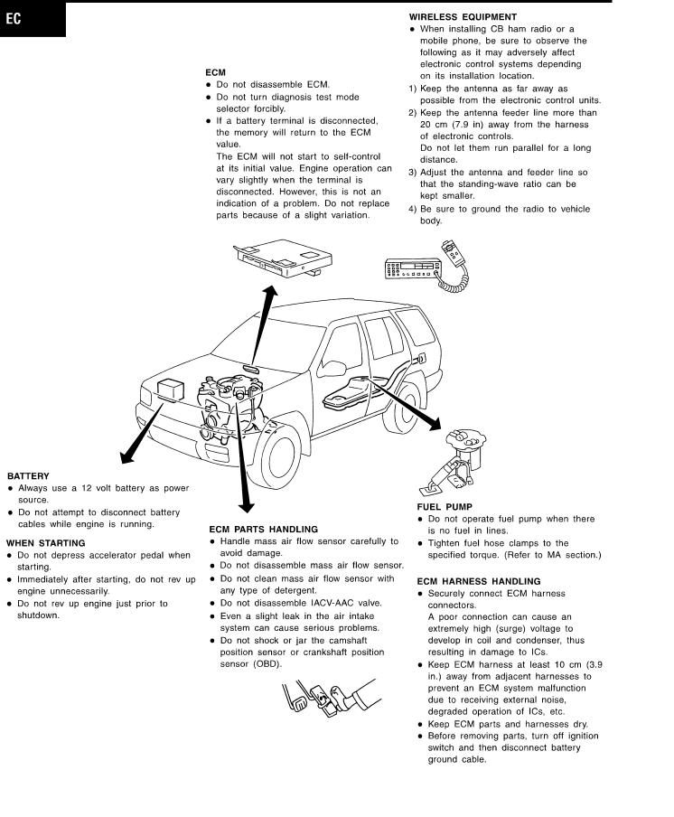
PRECAUTIONS
Engine Fuel & Emission Control System
Engine Fuel & Emission Control System
NAEC0004
SEF952RE
EC-15
GI
MA
EM
LC
FE
CL
MT
AT
TF
PD
AX
SU
BR
ST
RS
BT
HA
SC
EL
IDX

PRECAUTIONS
Precautions
Precautions
NAEC0005
I Before connecting or disconnecting the ECM harness connector, turn ignition switch OFF and disconnect negative battery terminal. Failure to do so may damage the ECM because battery voltage is applied to ECM even if ignition switch is turned off.
SEF289H
IWhen connecting ECM harness connector, fasten it securely with a lever as far as it will go as shown at left.
SEF908W
IWhen connecting or disconnecting pin connectors into or from ECM, take care not to damage pin terminals (bend or break).
Make sure that there are not any bends or breaks on ECM pin terminal, when connecting pin connectors.
SEF291H
IBefore replacing ECM, perform ªECM Terminals and Reference Valueº inspection and make sure ECM functions properly. Refer to EC-127.
MEF040D
IAfter performing each TROUBLE DIAGNOSIS, perform ªDTC Confirmation Procedureº or ªOverall Function Checkº.
The DTC should not be displayed in the ªDTC Confirmation Procedureº if the repair is completed. The ªOverall Function Checkº should be a good result if the repair is completed.
SEF217U
EC-16
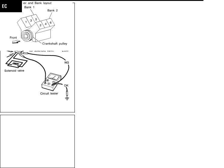
PRECAUTIONS
Precautions (Cont'd)
IWhen measuring ECM signals with a circuit tester, never allow the two tester probes to contact.
Accidental contact of probes will cause a short circuit and damage the ECM power transistor.
IDo not use ECM ground terminals when measuring input/ output voltage. Doing so may result in damage to the ECM's transistor. Use a ground other than the ECM terminals, such as the ground.
SEF348N
IRegarding model R50, ª-B1º indicates the right bank and ª-B2º indicates the left bank as shown in the figure.
IBank 1 includes No. 1 cylinder.
SEF099WB
Wiring Diagrams and Trouble Diagnosis
NAEC0006
When you read Wiring diagrams, refer to the following:
IGI-11, ªHOW TO READ WIRING DIAGRAMSº
IEL-12, ªPOWER SUPPLY ROUTINGº for power distribution circuit
When you perform trouble diagnosis, refer to the following:
IGI-35, ªHOW TO FOLLOW TEST GROUPS IN TROUBLE DIAGNOSESº
IGI-24, ªHOW TO PERFORM EFFICIENT DIAGNOSIS FOR AN ELECTRICAL INCIDENTº
EC-17
GI
MA
EM
LC
FE
CL
MT
AT
TF
PD
AX
SU
BR
ST
RS
BT
HA
SC
EL
IDX

PREPARATION
Special Service Tools
Special Service Tools
NAEC0007
The actual shapes of Kent-Moore tools may differ from those of special service tools illustrated here.
Tool number |
|
(Kent-Moore No.) |
Description |
Tool name |
|
|
|
KV10117100 |
Loosening or tightening front and rear heated oxy- |
(J36471-A) |
gen sensors with 22 mm (0.87 in) hexagon nut |
Front heated oxygen |
|
sensor wrench |
|
Rear heated oxygen |
|
sensor wrench |
|
|
NT379 |
|
|
(J44321) |
Checking fuel pressure with pressure gauge |
Fuel pressure adapter |
|
and gauge kit |
|
SEF326Z
|
Commercial Service Tools |
|
|
NAEC0008 |
|
Tool name |
Description |
|
(Kent-Moore No.) |
||
|
||
|
|
|
Leak detector |
Locating the EVAP leak |
|
(J41416) |
|
|
NT703 |
EVAP service port |
Applying positive pressure through EVAP service |
adapter |
port |
(J41413-OBD) |
|
|
NT704 |
Fuel filler cap adapter |
Checking fuel tank vacuum relief valve opening |
|
pressure |
NT653
EC-18

|
PREPARATION |
|
|
Commercial Service Tools (Cont'd) |
|
|
|
|
|
|
|
Tool name |
Description |
|
(Kent-Moore No.) |
||
|
||
|
|
|
Socket wrench |
Removing and installing engine coolant tempera- |
|
|
ture sensor |
|
NT705 |
Oxygen sensor thread |
Reconditioning the exhaust system threads before |
cleaner |
installing a new oxygen sensor. Use with anti- |
(J-43897-18) |
seize lubricant shown below. |
(J-43897-12) |
a: J-43897-18 18 mm diameter with pitch 1.5 |
|
mm, for Zirconia Oxygen Sensor |
|
b: J-43897-12 12 mm diameter with pitch 1.25 |
|
mm, for Titania Oxygen Sensor |
|
NT828 |
|
|
Anti-seize lubricant (Per- |
Lubricating oxygen sensor thread cleaning tool |
matexTM 133AR or |
when reconditioning exhaust system threads. |
equivalent meeting MIL |
|
specification MIL-A-907) |
|
NT779
EC-19
GI
MA
EM
LC
FE
CL
MT
AT
TF
PD
AX
SU
BR
ST
RS
BT
HA
SC
EL
IDX
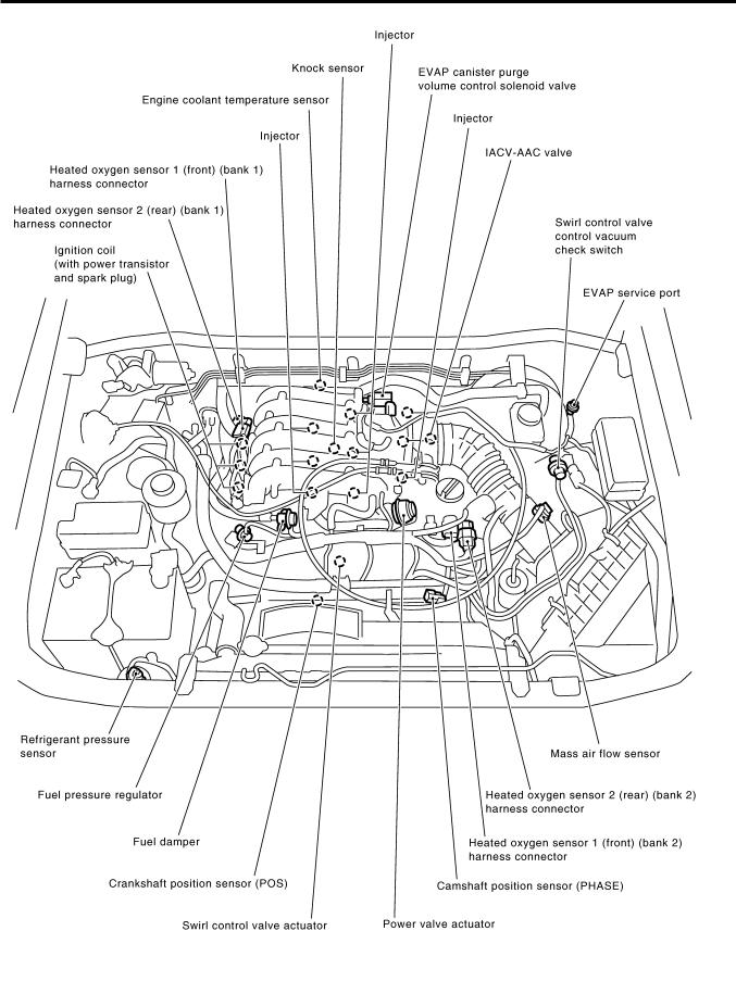
ENGINE AND EMISSION CONTROL OVERALL SYSTEM
Engine Control Component Parts Location
Engine Control Component Parts Location
NAEC0009
SEF952Z
EC-20
ENGINE AND EMISSION CONTROL OVERALL SYSTEM
Engine Control Component Parts Location (Cont'd)
GI
MA
EM
LC
FE
CL
MT
AT
TF
PD
AX
SU
BR
ST
RS
BT
HA
SC
EL
SEF034Z
IDX
EC-21
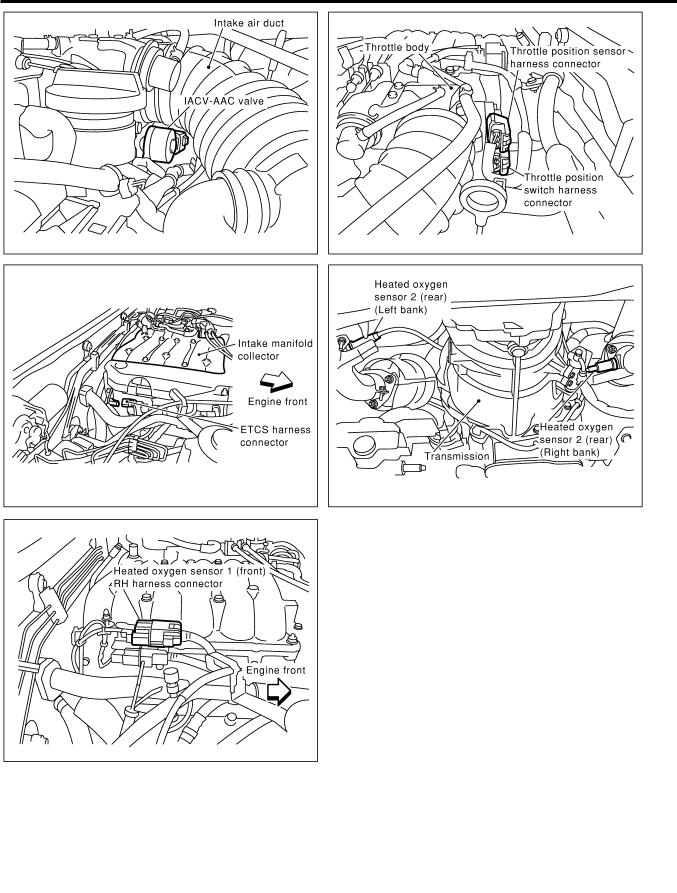
ENGINE AND EMISSION CONTROL OVERALL SYSTEM
Engine Control Component Parts Location (Cont'd)
SEF584Z
EC-22
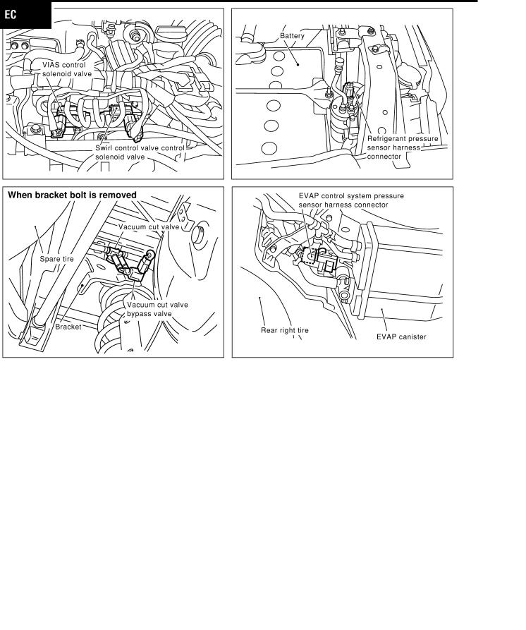
ENGINE AND EMISSION CONTROL OVERALL SYSTEM
Engine Control Component Parts Location (Cont'd)
GI
MA
EM
LC
FE
CL
MT
AT
TF
PD
AX
SU
BR
ST
RS
BT
HA
SC
EL
SEF036Z
IDX
EC-23
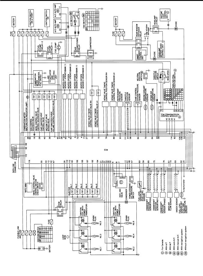
ENGINE AND EMISSION CONTROL OVERALL SYSTEM
Circuit Diagram
Circuit Diagram
NAEC0010
MODELS WITH SMART C/U Ð PREVIOUS
NAEC0010S01
MEC316D
EC-24

ENGINE AND EMISSION CONTROL OVERALL SYSTEM
Circuit Diagram (Cont'd)
MODELS WITH SMART C/U Ð NEW
NAEC0010S02
GI
MA
EM
LC
FE
CL
MT
AT
TF
PD
AX
SU
BR
ST
RS
BT
HA
SC
EL
MEC391D
IDX
EC-25
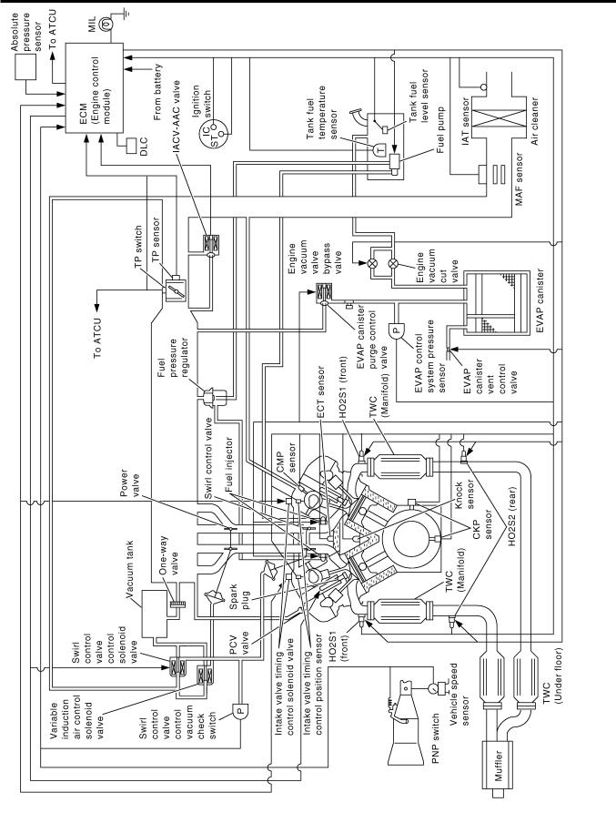
ENGINE AND EMISSION CONTROL OVERALL SYSTEM
System Diagram
System Diagram
NAEC0011
SEC306C
EC-26
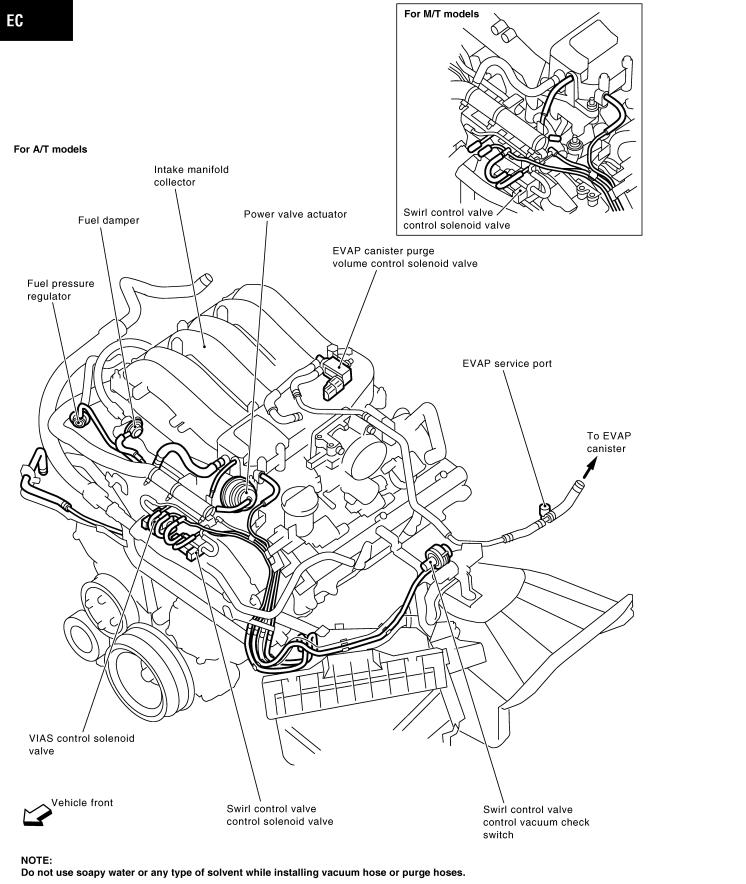
ENGINE AND EMISSION CONTROL OVERALL SYSTEM
|
Vacuum Hose Drawing |
|
Vacuum Hose Drawing |
|
GI |
|
NAEC0012 |
|
Refer to ªSystem Diagramº, EC-26 for Vacuum Control System.
MA
EM
LC
FE
CL
MT
AT
TF
PD
AX
SU
BR
ST
RS
BT
HA
SC
EL
IDX
SEF953Z
EC-27

ENGINE AND EMISSION CONTROL OVERALL SYSTEM
System Chart
System Chart
NAEC0013
Input (Sensor) |
ECM Function |
Output (Actuator) |
|
|
|
|
|
I Camshaft position sensor (PHASE) |
Fuel injection & mixture ratio control |
Injectors |
|
I Crankshaft position sensor (REF) |
|
|
|
Electronic ignition system |
Power transistor |
||
I Mass air flow sensor |
|||
|
|
||
I Engine coolant temperature sensor |
Idle air control system |
IACV-AAC valve |
|
I Heated oxygen sensor 1 (front) |
|||
|
|
||
|
|
||
I Ignition switch |
Fuel pump control |
Fuel pump relay |
|
I Throttle position sensor |
|
|
|
On board diagnostic system |
MIL (On the instrument panel) |
||
I Closed throttle position switch *3 |
|||
I Park/neutral position (PNP) switch |
|
Swirl control valve control solenoid |
|
I Air conditioner switch |
Swirl control valve control |
||
valve |
|||
I Knock sensor |
|
||
|
|
||
I Intake air temperature sensor |
Power valve control |
VIAS control solenoid valve |
|
I Absolute pressure sensor |
|
|
|
Heated oxygen sensor 1 heater (front) con- |
Heated oxygen sensor 1 heater |
||
I EVAP control system pressure sensor *1 |
|||
I Battery voltage |
trol |
(front) |
|
I Power steering oil pressure switch |
|
|
|
|
Heated oxygen sensor 2 heater |
||
I Vehicle speed sensor |
Heated oxygen sensor 2 heater (rear) control |
||
I Fuel tank temperature sensor *1 |
|
(rear) |
|
|
|
||
I Crankshaft position sensor (POS) |
EVAP canister purge flow control |
EVAP canister purge volume con- |
|
I Heated oxygen sensor 2 (rear)*2 |
trol solenoid valve |
||
|
|||
I TCM (Transmission control module) |
|
|
|
Air conditioning cut control |
Air conditioner relay |
||
I Refrigerant pressure sensor |
|||
I Electrical load |
|
|
|
|
I EVAP canister vent control valve |
||
I Fuel level sensor*1 |
ON BOARD DIAGNOSIS for EVAP system |
||
I Vacuum cut valve bypass valve |
|||
|
|
||
|
|
|
*1: These sensors are not used to control the engine system. They are used only for the on board diagnosis. *2: This sensor is not used to control the engine system under normal conditions.
*3: This switch will operate in place of the throttle position sensor to control EVAP parts if the sensor malfunctions.
EC-28

ENGINE AND EMISSION BASIC CONTROL SYSTEM DESCRIPTION
Multiport Fuel Injection (MFI) System
Multiport Fuel Injection (MFI) System
DESCRIPTION
NAEC0014
Input/Output Signal Chart
NAEC0014S01
Sensor |
Input Signal to ECM |
ECM func- |
Actuator |
|
tion |
||||
|
|
|
||
|
|
|
|
|
Crankshaft position sensor (POS) |
Engine speed (POS signal) |
|
|
|
|
|
|
|
|
Crankshaft position sensor (REF) |
Engine speed (REF signal) |
|
|
|
|
|
|
|
|
Camshaft position sensor (PHASE) |
Piston position |
|
|
|
|
|
|
|
|
Mass air flow sensor |
Amount of intake air |
|
|
|
|
|
|
|
|
Engine coolant temperature sensor |
Engine coolant temperature |
|
|
|
|
|
|
|
|
Heated oxygen sensor 1 (front) |
Density of oxygen in exhaust gas |
|
|
|
|
|
|
|
|
Throttle position sensor |
Throttle position |
|
|
|
Throttle valve idle position |
|
|
||
|
Fuel injec- |
|
||
|
|
|
||
Park/neutral position (PNP) switch |
Gear position |
tion & mix- |
Injectors |
|
|
|
ture ratio |
||
Vehicle speed sensor |
Vehicle speed |
|
||
control |
|
|||
|
|
|
|
|
Ignition switch |
Start signal |
|
|
|
|
|
|
|
|
Air conditioner switch |
Air conditioner operation |
|
|
|
|
|
|
|
|
Knock sensor |
Engine knocking condition |
|
|
|
|
|
|
|
|
Battery |
Battery voltage |
|
|
|
|
|
|
|
|
Absolute pressure sensor |
Ambient air barometric pressure |
|
|
|
|
|
|
|
|
Power steering oil pressure switch |
Power steering operation |
|
|
|
|
|
|
|
|
Heated oxygen sensor 2 (rear)* |
Density of oxygen in exhaust gas |
|
|
|
|
|
|
|
*: Under normal conditions, this sensor is not for engine control operation.
Basic Multiport Fuel Injection System
NAEC0014S02
The amount of fuel injected from the fuel injector is determined by the ECM. The ECM controls the length of time the valve remains open (injection pulse duration). The amount of fuel injected is a program value in the ECM memory. The program value is preset by engine operating conditions. These conditions are determined by input signals (for engine speed and intake air) from both the crankshaft position sensor and the mass air flow sensor.
GI
MA
EM
LC
FE
CL
MT
AT
TF
PD
AX
SU
BR
Various Fuel Injection Increase/Decrease Compensation
NAEC0014S03
In addition, the amount of fuel injected is compensated to improve engine performance under various operating conditions as listed below.
<Fuel increase>
IDuring warm-up
IWhen starting the engine
IDuring acceleration
IHot-engine operation
IWhen selector lever is changed from ªNº to ªDº
IHigh-load, high-speed operation
<Fuel decrease>
IDuring deceleration
IDuring high engine speed operation
EC-29
ST
RS
BT
HA
SC
EL
IDX

ENGINE AND EMISSION BASIC CONTROL SYSTEM DESCRIPTION
Multiport Fuel Injection (MFI) System (Cont'd)
Mixture Ratio Feedback Control (Closed loop control)
NAEC0014S04
SEF336WA
The mixture ratio feedback system provides the best air-fuel mixture ratio for driveability and emission control. The warm-up three way catalyst can then better reduce CO, HC and NOx emissions. This system uses a heated oxygen sensor 1 (front) in the exhaust manifold to monitor if the engine operation is rich or lean. The ECM adjusts the injection pulse width according to the sensor voltage signal. For more information about the heated oxygen sensor 1 (front) , refer to EC-187. This maintains the mixture ratio within the range of stoichiometric (ideal air-fuel mixture).
This stage is referred to as the closed loop control condition.
Heated oxygen sensor 2 (rear) is located downstream of the warm-up three way catalyst. Even if the switching characteristics of the heated oxygen sensor 1 (front) shift, the air-fuel ratio is controlled to stoichiometric by the signal from the heated oxygen sensor 2 (rear).
Open Loop Control
NAEC0014S05
The open loop system condition refers to when the ECM detects any of the following conditions. Feedback control stops in order to maintain stabilized fuel combustion.
IDeceleration and acceleration
IHigh-load, high-speed operation
IMalfunction of heated oxygen sensor 1 (front) or its circuit
IInsufficient activation of heated oxygen sensor 1 (front) at low engine coolant temperature
IHigh engine coolant temperature
IDuring warm-up
IAfter shifting from ªNº to ªDº
IWhen starting the engine
Mixture Ratio Self-learning Control
NAEC0014S06
The mixture ratio feedback control system monitors the mixture ratio signal transmitted from the heated oxygen sensor 1 (front). This feedback signal is then sent to the ECM. The ECM controls the basic mixture ratio as close to the theoretical mixture ratio as possible. However, the basic mixture ratio is not necessarily controlled as originally designed. Both manufacturing differences (i.e., mass air flow sensor hot wire) and characteristic changes during operation (i.e., injector clogging) directly affect mixture ratio.
Accordingly, the difference between the basic and theoretical mixture ratios is monitored in this system. This is then computed in terms of ªinjection pulse durationº to automatically compensate for the difference between the two ratios.
ªFuel trimº refers to the feedback compensation value compared against the basic injection duration. Fuel trim includes short term fuel trim and long term fuel trim.
ªShort term fuel trimº is the short-term fuel compensation used to maintain the mixture ratio at its theoretical value. The signal from the heated oxygen sensor 1 (front) indicates whether the mixture ratio is RICH or LEAN compared to the theoretical value. The signal then triggers a reduction in fuel volume if the mixture ratio is rich, and an increase in fuel volume if it is lean.
ªLong term fuel trimº is overall fuel compensation carried out long-term to compensate for continual deviation of the short term fuel trim from the central value. Such deviation will occur due to individual engine differences, wear over time and changes in the usage environment.
EC-30
Loading...