


 Loading...
STEERING SYSTEM
SECTION ST
CONTENTS
PRECAUTIONS AND PREPARATION ..................... |
2 |
Precautions ............................................................ |
2 |
Preparation............................................................. |
2 |
PREPARATION ......................................................... |
3 |
NOISE, VIBRATION AND HARSHNESS (NVH) |
|
TROUBLESHOOTING ............................................... |
4 |
NVH Troubleshooting Chart................................... |
4 |
ON-VEHICLE INSPECTION ...................................... |
5 |
Checking Steering Wheel Play .............................. |
5 |
Checking Neutral Position on Steering Wheel ...... |
5 |
Front Wheel Turning Angle.................................... |
5 |
Checking Gear Housing Movement....................... |
5 |
Checking and Adjusting Drive Belts ...................... |
6 |
Checking Fluid Level ............................................. |
6 |
Checking Fluid Leakage ........................................ |
6 |
Bleeding Hydraulic System.................................... |
6 |
Checking Steering Wheel Turning Force .............. |
7 |
Checking Hydraulic System................................... |
8 |
STEERING WHEEL AND STEERING COLUMN ..... |
9 |
Removal and Installation ..................................... |
10 |
Disassembly and Assembly................................. |
11 |
Inspection............................................................. |
12 |
POWER STEERING GEAR AND LINKAGE .......... |
14 |
|
|||||||
Removal and Installation ..................................... |
14 |
|
|||||||
Disassembly......................................................... |
17 |
|
|||||||
Inspection............................................................. |
17 |
|
|||||||
Assembly.............................................................. |
19 |
|
|||||||
|
|
|
GA16DE |
|
|
|
|
|
|
|
|
|
|
|
|
|
|||
POWER STEERING OIL PUMP ...................... |
20 |
|
|||||||
Pre-disassembly Inspection ................................. |
21 |
|
|||||||
Disassembly......................................................... |
21 |
|
|||||||
Inspection............................................................. |
22 |
|
|||||||
Assembly.............................................................. |
22 |
|
|||||||
|
|||||||||
POWER STEERING OIL PUMP.............................. |
24 |
ST |
|||||||
|
|
|
CD20T |
|
|
|
|
|
|
|
|
|
|
|
|
|
|
|
|
|
|
|
|
|
|
|
|
||
POWER STEERING OIL PUMP.............................. |
25 |
|
|||||||
POWER STEERING OIL PUMP.............................. |
26 |
|
|||||||
|
GA16DE, SR20De, CD20T, QG18 |
|
|
|
|
||||
|
|
|
|
|
|||||
SERVICE DATA AND SPECIFICATIONS (SDS) ... |
27 |
|
|||||||
General Specifications ......................................... |
27 |
|
|||||||
Inspection and Adjustment .................................. |
27 |
|
|||||||

PRECAUTIONS AND PREPARATION
Precautions
Supplemental Restraint System (SRS) ``AIR BAG'' and ``SEAT BELT PRE-TENSIONER''
The Supplemental Restraint System ``Air Bag'' and ``Seat Belt Pre-tensioner'', used along with a seat belt, help to reduce the risk or severity of injury to the driver and front passenger in a frontal collision. The Supplemental Restraint System consists of air bag modules (located in the center of the steering wheel and on the instrument panel on the passenger side), seat belt pre-tensioners, a diagnosis sensor unit, warning lamp, wiring harness and spiral cable.
If the vehicle is equipped with side air bag as the Supplemental Restraint System, the side air bag used along with the seat belt helps to reduce the risk or severity of injury to the driver and front passenger in a side collision. The side air bag consists of air bag modules (located in the outer side of front seats), satellite sensor, diagnosis sensor unit (which is one of components of air bags for a frontal collision), wiring harness, warning lamp (which is one of components of air bags for a frontal collision).
WARNING:
●To avoid rendering the SRS inoperative, which could increase the risk of personal injury or death (in the event of a collision which would result in air bag inflation), all maintenance must be performed by an authorized NISSAN dealer.
●Improper maintenance, including incorrect removal and installation of the SRS, can lead to personal injury caused by unintentional activation of the system.
●Do not use electrical test equipment on any circuit related to the SRS unless instructed to do so in this Service Manual. SRS wiring harnesses are covered with yellow insulation (either just before the harness connectors or for the complete harness), for easy identification.
STEERING SYSTEM
●Before disassembly, thoroughly clean the outside of the unit.
●Disassembly should be done in a clean work area. It is important to prevent the internal parts from becoming contaminated by dirt or other foreign matter.
●When disassembling parts, be sure to place them in order on a part rack so they can be reinstalled in their correct positions.
●Only use nylon cloths or paper towels to clean parts. Do not use rags or other materials containing lint. Residual debris may damage the system.
●Before inspection or reassembly, carefully clean all parts with a general purpose, non-flammable solvent.
●Before assembly, apply a coat of recommended ATF* to hydraulic parts. Vaseline may be applied to O-rings and seals. Do not use any grease.
●Replace all gaskets, seals and O-rings. Avoid damaging O-rings, seals and gaskets during installation. Perform functional tests whenever designated.
*: Automatic transmission fluid
|
Preparation |
|
|
SPECIAL SERVICE TOOL |
|
|
|
|
Tool number |
Description |
|
Tool name |
||
|
||
|
|
|
ST27180001 |
Removing and installing steering wheel |
|
Steering wheel puller |
|
NT170
ST-2

PREPARATION
|
SPECIAL SERVICE TOOLS |
|
|
|
|
Tool number |
Description |
|
Tool name |
||
|
||
|
|
|
KV48100700 |
Measuring pinion rotating torque |
|
Torque adapter |
|
HT72520000 |
Removing ball joint |
Ball joint remover |
|
ST27091000 |
|
To control |
Measuring oil pressure |
Pressure gauge |
To |
valve |
|
oil pump outlet |
|
|
|
|
|
|
|
|
Shut-off valve |
|
|
|
|
|
|
KV48102500 |
|
|
Measuring oil pressure |
Pressure gauge adapter |
|
|
|
ST3127S000 |
Measuring turning torque |
|
1 |
GG91030000 |
|
V |
Torque wrench |
|
|
|
|
2 |
HT62940000 |
|
V |
Socket adapter |
|
|
|
|
3 |
HT62900000 |
|
V |
Socket adapter |
|
|
|
|
ST-3

NOISE, VIBRATION AND HARSHNESS (NVH) TROUBLESHOOTING
NVH Troubleshooting Chart
Use the chart below to help you find the cause of the symptom.
If necessary, repair or replace these parts.
Reference page |
|
|
ST-6 |
ST-6 |
ST-18 |
ST-18 |
ST-19 |
ST-6 |
ST-5 |
ST-7 |
MAtoRefersection. |
Ð |
ST-12 |
ST-5 |
ST-13 |
ST-11 |
ST-14 |
FAinNVHsection |
FA,inNVHRA section |
FAinNVHsection |
FAinNCHsection |
BRinNVHsection |
|
|
|
|
|
|
|
|
|
|
|
|
|
|
|
|
|
|
|
|
|
|
|
||
|
|
|
|
|
|
|
|
|
|
|
|
|
|
|
|
|
|
|
|
|
|
|
|
Possible cause and |
|
|
levelFluid |
systemhydraulicinAir |
forceswingingjointballrod-Tie |
torquerotatingjointballrod-Tie |
playendjointballrod-Tie |
leakagefluidgearSteering |
playwheelSteering |
forceturningwheelSteering |
loosenessbeltDrive |
wheelsteeringImproper |
loosenessorinstallationImproperof tilt lock lever |
deteriorationrubberMounting |
deformationcolumnSteeringor damage |
loosenessorinstallationImproperof steering column |
loosenesslinkageSteering |
SHAFTDRIVE |
SUSPENSIONANDAXLE |
TIRES |
WHEELROAD |
BRAKES |
|
|
|
|
|
|
|
|
|
|
|
|
|
|
|
|
|
|
|
|
|
|
|
||
SUSPECTED PARTS |
|
|
|
|
|
|
|
|
|
|
|
|
|
|
|
|
|
|
|
|
|||
|
|
|
|
|
|
|
|
|
|
|
|
|
|
|
|
|
|
|
|
|
|
|
|
|
|
|
Noise |
X |
X |
X |
X |
X |
X |
X |
X |
X |
|
|
|
|
|
|
X |
X |
X |
X |
X |
|
|
|
|
|
|
|
|
|
|
|
|
|
|
|
|
|
|
|
|
|
|
|
|
|
|
|
Shake |
|
|
|
|
|
|
|
|
|
X |
X |
X |
|
|
|
X |
X |
X |
X |
X |
|
|
|
|
|
|
|
|
|
|
|
|
|
|
|
|
|
|
|
|
|
|
|
|
Symptom |
|
STEERING |
Vibration |
|
|
|
|
|
|
|
|
|
X |
X |
X |
X |
X |
|
X |
X |
X |
|
|
|
|
|
|
|
|
|
|
|
|
|
|
|
|
|
|
|
|
|
|
|
|
|
|
|
|
|
Shimmy |
|
|
|
|
|
|
|
|
|
X |
X |
X |
|
|
X |
|
X |
X |
X |
X |
|
|
|
|
|
|
|
|
|
|
|
|
|
|
|
|
|
|
|
|
|
|
|
|
|
|
|
Judder |
|
|
|
|
|
|
|
|
|
|
|
X |
|
|
X |
|
X |
X |
X |
X |
|
|
|
|
|
|
|
|
|
|
|
|
|
|
|
|
|
|
|
|
|
|
|
|
X: Applicable
ST-4

ON-VEHICLE INSPECTION
.SST489B
OK |
NG |
SST490BA
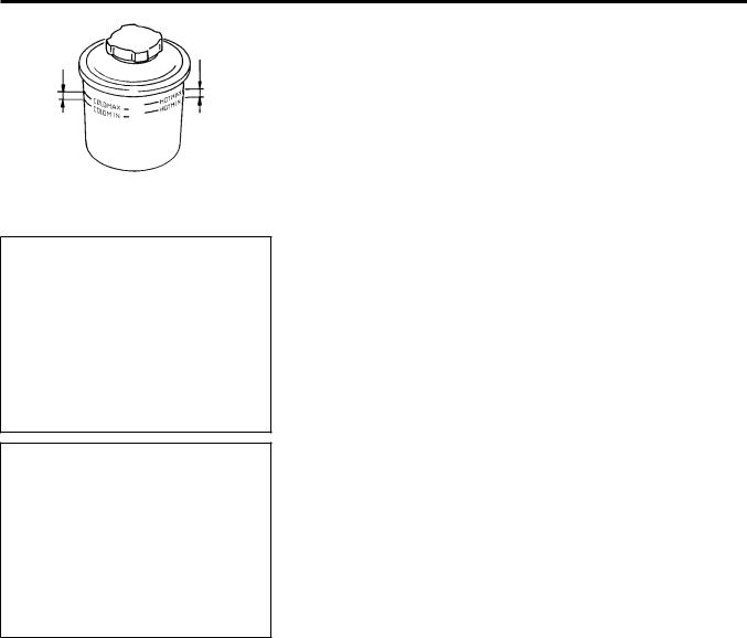
Checking Steering Wheel Play
1.With wheels in a straight-ahead position, check steering wheel play.
Steering wheel play:
35 mm (1.38 in) or less
2.If it is not within specification, check steering gear assembly when front suspension and axle, steering gear assembly and steering column are mounted correctly.
Checking Neutral Position on Steering Wheel
Pre-checking
●Make sure that wheel alignment is correct.
Wheel alignment:
Refer to SDS in FA section
●Verify that the steering gear is centered before removing the steering wheel.
Checking
1.Check that the steering wheel is in the neutral position when driving straight ahead.
2.If it is not in the neutral position, remove the steering wheel and reinstall it correctly.
3.If the neutral position is between two serrated teeth, loosen tie-rod lock nut and move tie-rod in the opposite direction by the same amount on both left and right sides to compensate for error in the neutral position.
Front Wheel Turning Angle
1.Rotate steering wheel all the way right and left; measure turning angle.
Turning angle of full turns: Refer to SDS in FA section
2.If it is not within specification, check rack stroke.
Rack stroke ``S'':
Refer to SDS (ST-27)
SMA127
Checking Gear Housing Movement
1.Check the movement of steering gear housing during stationary steering on a dry paved surface.
●Apply a force of 49 N (5 kg, 11 lb) to steering wheel to check the gear housing movement.
Turn off ignition key while checking.
Movement of gear housing: ±2 mm (±0.08 in) or less
2. If movement exceeds the limit, replace mount insulator after
. confirming correct installation of gear housing clamps.
SST059B
ST-5
ON-VEHICLE INSPECTION
|
HOT: |
COLD: |
50 - 80°C |
0 - 30°C |
(122 - 176°F) |
(32 - 86°F) |
|
NST031
SST681B
Checking and Adjusting Drive Belts
Refer to section MA for Drive Belt Inspection.
Checking Fluid Level
Check fluid level.
Fluid level should be checked using ``HOT'' range on dipstick at fluid temperatures of 50 to 80°C (122 to 176°F) or using ``COLD'' range on dipstick at fluid temperatures of 0 to 30°C (32 to 86°F).
CAUTION:
●Do not overfill.
●Recommended fluid is Automatic Transmission Fluid ``DEXRONTM'' type.
Checking Fluid Leakage
Check the lines for security, leaks, cracks, damage, loose connections, chafing or deterioration.
1. Run engine between idle speed and 1,000 rpm.
Make sure temperature of fluid in oil tank rises to 60 to 80°C (140 to 176°F).
2.Turn steering wheel right-to-left several times.
3.Hold steering wheel at each ``lock'' position for five seconds and carefully check for fluid leakage.
CAUTION:
Do not hold the steering wheel in a locked position for more than 15 seconds.
4. If fluid leakage at connectors is noticed, loosen flare nut and then retighten.
Do not overtighten connector as this can damage O-ring, washer and connector.
5. Check rack boots for accumulation of power steering fluid.
Bleeding Hydraulic System
1.Raise front end of vehicle until wheels are clear of the ground.
2.Add fluid into oil tank to specified level. Then quickly turn steering wheel fully to right and left and lightly touch steering stoppers.
Repeat steering wheel operation until fluid level no longer decreases.
3.Start engine.
Repeat step 2 above.
ST-6

ON-VEHICLE INSPECTION
Bleeding Hydraulic System (Cont'd)
After turning 360°
SST491B
SST090B
●Incomplete air bleeding will cause the following to occur. When this happens, bleed air again.
a.Generation of air bubbles in reservoir tank
b.Generation of clicking noise in oil pump
c.Excessive buzzing in oil pump
While the vehicle is stationary or while moving the steering wheel slowly, fluid noise may occur in the valve or oil pump. This noise is inherent in this steering system, and it will not affect performance or durability of the system.
Checking Steering Wheel Turning Force
1.Park vehicle on a level, dry surface and set parking brake.
2.Start engine.
3.Bring power steering fluid up to adequate operating temperature. [Make sure temperature of fluid is approximately 60 to
80°C (140 to 176°F).]
Tires need to be inflated to normal pressure.
4.Check steering wheel turning force when steering wheel has been turned 360° from neutral position.
Steering wheel turning force:
44.1 N (4.5 kg, 9.9 lb) or less
5.If steering wheel turning force is out of specification, check rack sliding force to detect condition of steering gear assem-
bly.
a.Disconnect steering column lower joint and knuckle arms from the gear.
b.Start and run engine at idle to make sure steering fluid has reached normal operating temperature.
c.While pulling tie-rod slowly from the neutral position, make sure rack sliding force is within specification.
Rack sliding force:
284 N (29 kg, 64 lb) or less
6.If rack sliding force is not within specification, replace steering gear assembly.
ST-7

ON-VEHICLE INSPECTION
ST27091000
Pump
Tank
Direction of oil flow
Highpressure hose
Gear
Low-pressure hose
SST834
Checking Hydraulic System
Before starting, check belt tension, driving pulley and tire pressure.
1.Set Tool. Open shut-off valve. Then bleed air. (See ``Bleeding Hydraulic System''.)
2.Run engine.
Make sure temperature of fluid in tank rises to 60 to 80°C (140 to 176°F).
WARNING:
Warm up engine with shut-off valve fully opened. If engine is started with shut-off valve closed, oil pressure in oil pump will increase to relief pressure, resulting in an abnormal rise in oil temperature.
3. Check pressure with steering wheel fully turned to left and right positions with engine idling at 1,000 rpm.
CAUTION:
Do not hold the steering wheel in a locked position for more than 15 seconds.
Oil pump maximum standard pressure: GA: 7,649 - 8,238 kPa
(76.5 - 82.4 bar, 78 - 84 kg/cm2, 1,109 - 1,194 psi)
QG: 7,502 - 8,101 kpa
(75 - 81 bar, 76.5 - 82.6 kg/cm2, 1,088 - 1,175 psi)
SR: 7,002 - 7,600 kPa
(70 - 76 bar, 71.4 - 77.5 kg/cm2, 1,015 - 1,102 psi)
CD: 7,690 - 8,493 kpa
(77 - 85 bar, 78,5 - 86,6 kg/cm2, 1,116 - 1,231 psi)
4.If oil pressure is below the standard pressure, slowly close shut-off valve and check pressure.
●When pressure reaches above standard pressure, gear is damaged.
●When pressure remains below standard pressure, pump is damaged.
CAUTION:
Do not close shut-off valve for more than 15 seconds.
5.If oil pressure is higher than standard pressure, check oil pump flow control valve (GA engine models only).
6.After checking hydraulic system, remove Tool and add fluid as necessary, then completely bleed air out of system.
ST-8

STEERING WHEEL AND STEERING COLUMN
Spiral cable
SEC. 484c487c488
Upper column cover
Horn pad
29 - 39 (Including Airbag
(3.0 - 4.0, module)
22 - 29)
Steering column assembly
Ignition switch grommet |
Steering wheel |
13 - 18
(1.3 - 1.8, 9 - 13)
Lower column cover
15 - 19
(1.5 - 1.9, 11 - 14)
: N´m (kg-m, ft-lb)
Push-on nut
NST019
CAUTION:
●The rotation of the spiral cable (SRS ``Air bag'' component part) is limited. If the steering gear must be removed, set the front wheels in the straight-ahead direction. Do not rotate the steering column while the steering gear is removed.
●Remove the steering wheel before removing the steering lower joint to avoid damaging the SRS spiral cable.
ST-9
Loading...