


 Loading...
BODY & TRIM
SECTION BT
CONTENTS
PRECAUTIONS ......................................................... |
2 |
Service Notice........................................................ |
2 |
Supplemental Restraint System (SRS) ``AIR |
|
BAG'' and ``SEAT BELT PRE-TENSIONER'' ........ |
2 |
GENERAL SERVICING ............................................. |
3 |
Clip and Fastener .................................................. |
3 |
BODY END ................................................................ |
5 |
Body Front End...................................................... |
5 |
Body Rear End and Opener .................................. |
7 |
DOOR....................................................................... |
13 |
Front Door............................................................ |
13 |
Rear Door ............................................................ |
14 |
INSTRUMENT PANEL............................................. |
15 |
INTERIOR TRIM ...................................................... |
18 |
Side and Floor Trim ............................................. |
18 |
Door Trim ............................................................. |
24 |
Roof Trim ............................................................. |
25 |
Trunk Room Trim................................................. |
28 |
Luggage Room Trim ............................................ |
62 |
Back Door Trim.................................................... |
30 |
EXTERIOR ............................................................... |
31 |
SEAT ........................................................................ |
40 |
Front Seat ............................................................ |
40 |
Heated Seat ......................................................... |
42 |
Rear Seat............................................................. |
43 |
SUNROOF................................................................ |
46 |
Trouble Diagnoses............................................... |
49 |
WINDSHIELD AND WINDOWS .............................. |
53 |
Windshield and Rear Window ............................. |
54 |
Side Window ........................................................ |
55 |
Back Door Window .............................................. |
56 |
MIRROR ................................................................... |
58 |
Door Mirror........................................................... |
58 |
Rearview Mirror.................................................... |
59 |
BODY ALIGNMENT................................................. |
60 |
Engine Compartment ........................................... |
60 |
Underbody............................................................ |
62 |
BT

PRECAUTIONS
Service Notice
●When removing or installing various parts, place a cloth or padding onto the vehicle body to prevent scratches.
●Handle trim, molding, instruments, grille, etc. carefully during removing or installing. Be careful not to soil or damage them.
●Apply sealing compound where necessary when installing parts.
●When applying sealing compound, be careful that the sealing compound does not protrude from parts.
●When replacing any metal parts (for example body outer panel, members, etc.), be sure to take rust prevention measures.
Supplemental Restraint System (SRS) ``AIR
BAG'' and ``SEAT BELT PRE-TENSIONER''
The Supplemental Restraint System ``Air Bag'' and ``Seat Belt Pre-tensioner'', used along with a seat belt, helps to reduce the risk or severity of injury to the driver and front passenger in a frontal collision. The Supplemental Restraint System consists of air bag modules (located in the center of the steering wheel and on the instrument panel on the passenger side), seat belt pre-tensioners, a diagnosis sensor unit, warning lamp, wiring harness and spiral cable. Information necessary to service the system safely is included in the RS section of the Service Manual.
If the vehicle is equipped with side air bag as the Supplemental Restraint System, the side air bag used along with the seat belt helps to reduce the risk or severity of injury to the driver and front passenger in a side collision. The side air bag consists of air bag modules (located in the outer side of front seats), satellite sensor, diagnosis sensor unit (which is one of components of air bags for a frontal collision), wiring harness, warning lamp (which is one of components of air bags for a frontal collision).
WARNING:
●To avoid rendering the SRS inoperative (which could increase the risk of personal injury or death in the event of a collision which would result in air bag inflation) all maintenance must be performed by an authorized NISSAN dealer.
●Improper maintenance, including incorrect removal and installation of the SRS, can lead to personal injury caused by unintentional activation of the system.
●Do not use electrical test equipment on any circuit related to the SRS unless instructed to do so in this Service Manual. SRS wiring harnesses are covered with yellow insulation (either just before the harness connectors or for the complete harness) for easy identification.
BT-2

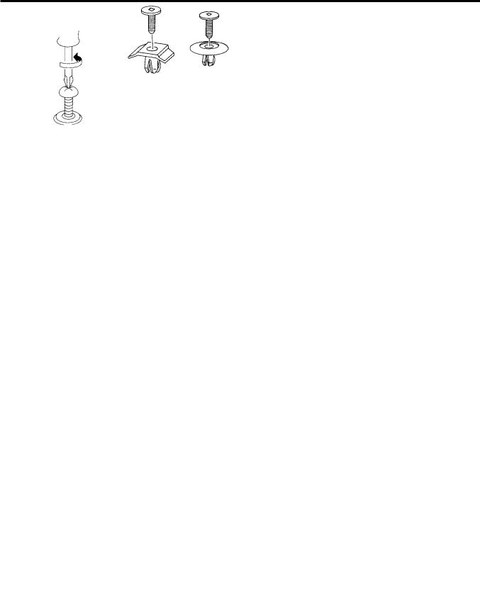
GENERAL SERVICING
Clip and Fastener
●Clips and fasteners in BT section correspond to the following numbers and symbols.
●Replace any clips and/or fasteners which are damaged during removal or installation.
Symbol |
Shapes |
Removal & Installation |
||
No. |
||||
|
|
|
||
|
|
|
||
|
|
Removal: |
||
|
|
Remove by bending up with |
||
|
|
flat-bladed screwdrivers or |
||
|
|
clip remover. |
||
C101 |
|
|
|
|
|
SBF302H |
|
SBF367BA |
|
|
|
|
|
|
C103 |
|
|
|
|
|
|
Removal: |
|
|
|
|
Remove with a clip remover. |
||
|
SBT095 |
|
SBF423H |
|
|
|
|
|
|
|
|
|
Push center pin to |
|
|
|
Push |
catching position. |
|
|
|
(Do not remove |
||
|
|
|
||
|
|
|
center pin by hitting it.) |
|
C203 |
|
|
|
|
|
|
|
Push |
|
|
|
|
Installation: |
|
|
SBF258G |
|
SBF708E |
|
|
|
|
|
|
|
|
Removal: |
|
|
|
|
|
Screwdriver |
|
C205 |
|
|
|
|
|
|
|
Clip |
|
|
|
|
Finisher |
|
|
MBT080A |
|
SBF638C |
|
|
|
|
|
|
BT-3
GENERAL SERVICING
Clip and Fastener (Cont'd)
Symbol |
Shapes |
Removal & Installation |
||
No. |
||||
|
|
|
||
|
|
|
|
|
|
|
Removal: |
|
|
|
|
Remove by bending up with a |
||
|
|
flat-bladed screwdriver or pliers. |
||
CE117 |
|
|
|
|
|
SBF174D |
|
SBF175DA |
|
|
|
|
|
|
|
|
Removal: |
|
|
|
Clip-A |
Flat-bladed screwdriver |
||
|
|
Finisher |
||
|
|
|
||
CF118 |
|
|
|
|
|
Clip-B |
|
Clip-B |
|
|
(Grommet) |
Body |
(Grommet) |
|
|
Sealing |
panel |
Clip-A |
|
|
|
Sealing |
||
|
washer |
|
||
|
|
washers |
||
|
|
|
||
|
SBF151D |
|
SBF259G |
|
|
|
|
|
|
|
|
Removal: |
|
|
|
|
Holder portion of clip must be spread |
||
|
|
out to remove rod |
||
CR103 |
|
|
|
|
|
|
|
SBF770B |
|
|
SBF768B |
|
|
|
|
|
|
|
|
|
|
Removal: |
|
|
|
|
1. Screw out with a Phillips screwdriver. |
||
|
|
2. Remove female portion with flat-bladed |
||
|
|
screw-driver. |
|
|
CS101 |
|
|
|
|
|
SBF078B |
|
SBF992G |
|
|
|
|
|
|
BT-4

BODY END
Body Front End
●When removing or installing hood, place a cloth or other padding on the front fender panels and cowl top. This prevents vehicle body from being scratched.
●Bumper fascia is made of plastic. Do not use excessive force and be sure to keep oil away from it.
●Hood adjustment: Adjust at hinge portion.
●Hood lock adjustment: After adjusting, check hood lock control operation. Apply a coat of grease to hood locks engaging mechanism.
●Hood opener: Do not attempt to bend cable forcibly. Doing so increases effort required to unlock hood.
REMOVAL Ð Front bumper assembly
V1 Remove clips C205 securing bumper fascia to engine undercover.
V2 Remove screws and clips C205 securing left and right sides of front fender protector. V3 Remove screws securing radiator core support to bumper fascia.
V4 Remove screws securing left and right front fenders to bumper fascia.
V5 Remove clips CS101 securing retainer to bumper fascia.
V6 Extract bumper fascia assembly.
V7 Remove screws securing fog lamps. Then remove fog lamps.
10.8 - 14.6 N´m
(1.1 - 1.5 kg-m,
8.0 - 10.8 ft-lb)
YBT001
BT-5

BODY END
Body Front End (Cont'd)
SEC. 261c620c623c650c656
Hood lock adjustment |
|
|
● Adjust hood so that hood primary lock |
|
|
meshes at a position 1 to 1.5 mm (0.039 to |
Hood adjustment |
|
0.059 in) lower than fender. |
||
|
●After hood lock adjustment, adjust bumper rubber.
●When securing hood lock, ensure it does not tilt. Striker must be positioned at the center of hood primary lock.
●After adjustment, ensure that hood primary and
secondary lock operate properly.
.
Hood lock secondary latch hooking length
Bumper rubber adjustment
●Adjust so that hood is aligned with fender. At that time deflection is approx. 2 mm (0.08
in).
[Bumper rubber free height is approx. 13 mm (0.51 in).]
20.6 - 26.5
(2.1 - 2.7,
15 - 20)
C205
CS101 |
. |
C205
.
Fog lamp
. 
Bumper fascia assembly
. 
.
.: Bumper assembly mounting bolts, screw & clips
 : N´m (kg-m, ft-lb)
NBT033
BT-6

BODY END
Body Rear End and Opener
4-DOOR SEDAN
●When removing or installing trunk lid, place a cloth or other padding on rear fender panels. This prevents vehicle body from being scratched.
●Bumper fascia is made of plastic. Do not use excessive force and be sure to keep oil away from it.
●Trunk lid adjustment: Adjust at hinge-trunk lid portion for proper trunk lid fit.
●Trunk lid lock system adjustment: Adjust striker so that it is in the center of the lock. After adjustment, check trunk lid lock operation.
WARNING:
● Be careful not to scratch trunk lid stay when installing trunk lid.
A scratched stay may cause gas leakage.
● The contents of the trunk lid stay are under pressure. Do not take apart puncture, apply heat or allow fire near it.
● Opener cable: Do not attempt to bend cable using excessive force.
● After installation, make sure that trunk lid and fuel filler lid open smoothly.
5.1 - 6.37 |
|
|
(0.52 - 0.65, |
|
|
45.1 - 56.4) |
Actuator |
|
. |
|
|
Trunk lid lock |
|
|
key cylinder |
. |
|
5.1 - 6.37 |
|
|
. |
20.6 - 26.5 |
|
Trunk lid lock |
(0.52 - 0.65, 45.1 - 56.4) |
|
|
|
(2.1 - 2.7, |
|
|
15 - 20) |
Upper |
|
|
Opener handle |
|
Opener cable |
Spring holder |
|
|
|
|
Lock nut |
Lower |
|
|
|
|
Fuel filler lid opener & control |
Trunk lid striker |
|
|
. |
|
|
5.1 - 6.37 |
|
|
(0.52 - 0.65, |
|
|
45.1 - 56.4) |
|
|
|
Cloth |
: N´m (kg-m, in-lb) |
|
|
|
|
|
: N´m (kg-m, ft-lb) |
|
|
NBT034 |
BT-7

BODY END
Body Rear End and Opener (Cont'd)
REMOVAL Ð Rear bumper assembly
V1 Remove license plate lamp.
V2 Remove clips C203 securing left and right chipping protector.
V3 Remove screws securing bumper fascia to left and right rear fenders.
V4 Remove clips CS101 securing bumper fascia to real panel.
V5 Remove clips C205 securing bumper fascia to rear panel upper.
V6 Extract bumper fascia assembly.
SEC. 843c844c850c998
5.1 - 6.37
(0.52 - 0.65,
45.1 - 56.4)
Trunk lid lock control |
Trunk lid adjustment |
Trunk lid stay 
Trunk lid hinge 
 Opener handle
Fuel filler lid control 
Trunk lid striker adjustment 
.
C205
C203
.
.
Bumper fascia assembly
|
CS101 |
CS101 |
|
. |
|
. |
|
|
|
: N´m (kg-m, in-lb) |
. : Bumper assembly mounting clips and screws.
NBT035
BT-8

BODY END
Body Rear End and Opener (Cont'd)
5-DOOR HATCHBACK
●Back door adjustment: Adjust at hinge-body portion for proper back door fit.
●Back door lock system adjustment: Adjust lock & striker so that they are in the center. After adjustment, check back door lock operation.
WARNING:
● Be careful not to scratch back door stay when installing back door. A scratched stay may cause gas leakage.
● The contents of the back door stay are under pressure. Do not take apart, puncture, apply heat or allow fire near it.
● Opener cable: Do not attempt to bend cable using excessive force.
● After installation, make sure that back door and fuel filler lid open smoothly.
|
12.7 - 15.7 |
12.7 - 15.7 |
|
(1.30 - 1.60, |
|
|
(1.30 - 1.60, |
|
|
9.4 - 11.6) |
|
|
9.4 - 11.6) |
|
|
|
|
20.6 - 26.5 |
|
|
(2.10 - 2.70, |
|
|
15.2 - 19.5) |
|
|
Opener handle |
Opener cable |
|
|
Lock nut |
|
|
|
12.7 - 15.7 |
|
|
(1.30 - 1.60, |
|
Fuel filler lid opener & control |
9.4 - 11.6) |
|
|
|
|
|
. |
|
|
5.1 - 6.37 |
|
|
(0.52 - 0.65, 45.1 - 56.4) |
|
|
Actuator |
|
|
Key |
|
|
cylinder |
20.6 - 26.5 |
Cloth |
|
|
|
|
(2.10 - 2.70, |
|
|
15.2 - 19.5) |
|
|
|
|
: N´m (kg-m, ft-lb) |
|
|
NBT036 |
REMOVAL Ð Rear bumper assembly
V1 Remove license plate lamp
V2 Remove clips C203 securing left and right chipping protector.
V3 Remove screws securing bumper fascia to left and right rear fenders.
V4 Remove clips CS101 securing bumper fascia to rear panel.
V5 Remove clips C205 securing bumper fascia to rear panel upper.
V6 Extract bumper fascia assembly.
BT-9

BODY END
Body Rear End and Opener (Cont'd)
SEC. 850c900c905
|
Back door stay |
Back door lock control |
installation |
|
|
Back door lock adjustment |
|
Back door hinge adjustment 
 Opener handle
Fuel filler lid control 
Back door striker adjustment 
.
CS205
C203
 .
.
Bumper fascia assembly
|
CS101 |
CS101 |
|
. |
|
. |
|
|
|
|
. : Bumper assembly mounting clips and screws.
NBT037
BT-10
BODY END
Body Rear End and Opener (Cont'd)
WAGON
●Back door adjustment: Adjust at hinge-body portion for proper back door fit.
●Back door lock system adjustment: Adjust lock & striker so that they are in the center. After adjustment, check back door lock operation.
WARNING:
● Be careful not to scratch back door stay when installing back door. A scratched stay may cause gas leakage.
● The contents of the back door stay are under pressure. Do not take apart, puncture, apply heat or allow fire near it.
● Fuel filler lid opener cable: Do not attempt to bend cable using excessive force. ● After installation, make sure that back door and fuel filler lid open smoothly.
|
|
12.7 - 15.7 |
12.7 - 15.7 |
|
|
(1.30 - 1.60, |
|
|
|
(1.30 - 1.60, |
|
|
|
9.4 - 11.6) |
|
|
|
9.4 - 11.6) |
|
|
|
|
|
. |
|
|
|
20.6 - 26.5 |
|
|
|
(2.10 - 2.70, |
|
|
|
15.2 - 19.5) |
|
|
|
Opener handle |
|
|
|
Opener |
|
Lock nut |
|
|
|
|
|
cable |
|
|
|
|
|
|
12.7 - 15.7 |
|
|
|
(1.30 - 1.60, |
|
. |
Fuel filler lid opener & control |
9.4 - 11.6) |
|
|
||
|
|
|
. |
. |
|
|
2.9 - 3.8 N´m |
|
||
5.1 - 6.37 |
Key cylinder |
||
(0.30 - 0.39 kg-m, |
(0.52 - 0.65, |
||
|
|||
25.7 - 33.6 in-lb) |
45.1 - 56.4) |
|
|
|
Actuator |
|
|
. |
|
|
|
12.7 - 15.7 |
|
|
|
(1.30 - 1.60, |
|
|
|
9.4 - 11.6) |
|
|
|
: N´m (kg-m, ft-lb) |
|
|
|
: N´m (kg-m, in-lb) |
|
NBF270 |
|
|
|
REMOVAL Ð Rear bumper assembly
V1 Remove clips C203 securing left and right chipping protector.
V2 Remove screws securing bumper fascia to left and right rear fenders.
V3 Remove clips C205 (small) securing bumper fascia to rear panel.
V4 Remove clips C205 (large) securing bumper fascia to rear panel upper.
V5 Extract bumper fascia assembly.
BT-11

BODY END
Body Rear End and Opener (Cont'd)
Back door lock control 
Back door lock adjustment |
Back door stay installation |
|
Back door hinge adjustment 
Opener handle
Fuel filler lid control 
Rear fender cover 
Back door striker adjustment 
Bumper fascia assembly
* : Bumper assembly mounting clips and screws.
NBF271
BT-12
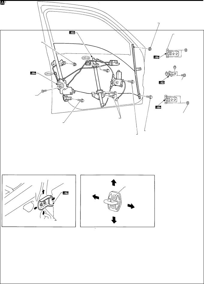
DOOR
Front Door
●For removal of door trim, refer to ``Door Trim'' in ``INTERIOR TRIM'' for details, BT-24.
●After adjusting door or door lock, check door lock operation.
SEC. 800c803c805
2.93 - 3.82
(0.30 - 0.39,
25.9 - 33.8)
Door-hinge
adjustment
5.1 - 6.37
(0.52 - 0.65, 45.1 - 56.4)
5.1 - 6.37
(0.52 - 0.65,
5.1 - 6.37 45.1 - 56.4)
(0.52 - 0.65,
45.1 - 56.4)
|
|
6.08 - 7.75 |
20.6 - 26.5 |
|
6.08 |
- 7.75 |
(0.62 - 0.79, |
(2.1 - 2.7, |
|
53.8 - 68.6) |
15 - 20) |
|||
(0.62 - 0.79, |
||||
|
|
|||
53.8 |
- 68.6) |
|
|
|
6.08 |
- 7.75 |
6.08 - 7.75 |
|
(0.62 - 0.79, |
|||
(0.62 - 0.79, |
|||
53.8 |
- 68.6) |
||
53.8 - 68.6) |
|||
|
|
||
Door-hinge adjustment |
Striker adjustment |
13 - 16
(1.3 - 1.6,
9 - 12)
|
: N´m (kg-m, ft-lb) |
20.6 - 26.5 (2.1 - 2.7, 15 - 20) |
: N´m (kg-m, in-lb) |
|
: Apply grease |
NBT038
BT-13

DOOR
Rear Door
SEC. 820c823c825
5.1 - 6.37
(0.52 - 0.65,
45.1 - 56.4)
5.1 - 6.37
(0.52 -0.65,
45.1 - 56.4)
Door-hinge adjustment
20.6 - 26.5
(2.1 - 2.7,
15 - 20)
1.47- 1.86
(0.15 - 0.19,
13.0 - 16.5)
6.08 - 7.75
(0.62 - 0.79,
53.8 - 68.6)
Door-hinge adjustment 
20.6 - 26.5
(2.1 - 2.7,
15 - 20)
5.1 - 6.37
(0.52 - 0.65,
45.1 - 56.4)
6.08 - 7.75
(0.62 - 0.79,
53.8 - 68.6)
6.08 - 7.75
(0.62 - 0.79,
53.8 - 68.6)
Striker adjustment
13 - 16
(1.3 - 1.6,
9 - 12)
: N´m (kg-m, ft-lb)
: N´m (kg-m, in-lb)
: Apply grease
NBT039
BT-14

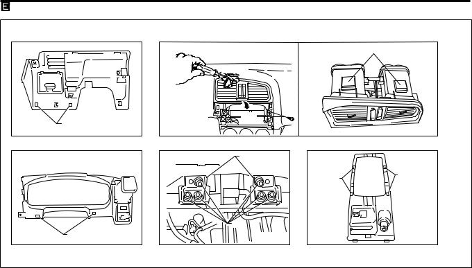
INSTRUMENT PANEL
CAUTION:
●Disconnect both battery cables in advance.
●Disconnect air bag system line in advance.
●Never tamper with or force air bag lid open, as this may adversely affect air bag performance.
●Be careful not to scratch pad and other parts.
REMOVAL Ð Instrument panel assembly
Instrument panel assembly |
|
Combination meter |
|
Audio & A/C control |
|
Console box |
||
|
|
|
|
|
|
|
|
|
|
|
|
|
|
|
|
|
|
Remove air bag module (driver's) and steering wheel.
Refer to ``SUPPLEMENTAL RESTRAINT SYSTEM'' in RS section for details.
V1 Steering column cover and combination switch ● Remove screws.
V2 Instrument lower panel on driver side ● Remove screws.
V3 Cluster lid A
● Remove screws.
V4 Combination meter
● Remove screws and disconnect harness connectors.
V5 Audio
V6 Center ventilator
●Remove screws.
●Pull out with a miniature flat-bladed screwdriver.
V7 A/C or heated control ● Remove screws.
V8 Audio bracket
V9 Glove box assembly
●Remove glove box pin.
●Then disconnect passenger air bag module connector.
V10 Passenger air bag module
● Refer to ``SUPPLEMENTAL RESTRAINT SYSTEM'' in RS section for details.
V11 Lower cover
● Remove clip
V12 AT finisher or MT shift lever boot
V13 Rear console box
● Remove console mask and screws.
V14 Front console box
● Remove screws and bolts.
V15 Front defroster grill
● Disconnect harness connector.
V16 Front pillar garnish
● Refer to ``Side and Floor Trim'' in ``INTERIOR TRIM'' for details, BT-18.
V17 Instrument panel and pads ● Remove nuts and bolts.
● Remove door mirror switch and disconnect the connector.
BT-15

INSTRUMENT PANEL
SEC. 248c251c272c487c680c685c969
 2.8 - 4.8 (0.29 - 0.49, 24.8 - 42.5)
. .
|
. |
. |
|
|
|
. |
|
14.7 - 24.5 |
|
(1.50 - 2.5, |
|
|
|
|
|
|
10.8 - 18.1) |
.
Metal clip 
|
Metal clip |
Metal clip |
Metal clip |
|
Metal clip |
 : N´m (kg-m, in-lb)
 : N´m (kg-m, ft-lb)
. : Instrument panel assembly mounting bolts & nuts.
NBT040
BT-16
INSTRUMENT PANEL
|
Hook |
|
. |
|
|
Cloth |
|
|
. |
|
|
Pull |
|
|
Metal clip |
|
|
Bracket |
|
|
Metal |
Metal |
|
clip |
||
clip |
||
|
||
Bolt |
|
|
Metal clip |
|
|
|
NBT041 |
BT-17
INTERIOR TRIM
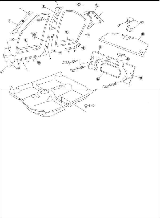
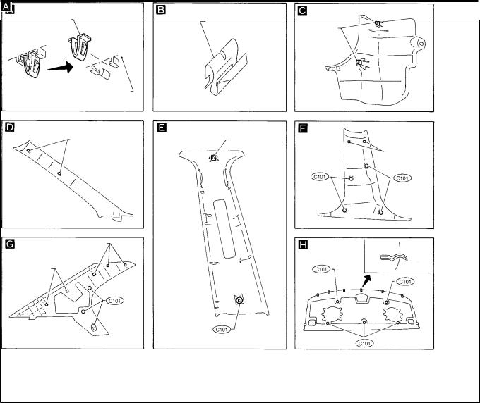
Side and Floor Trim
CAUTION:
Wrap the tip of flat-bladed screwdriver with a cloth when removing metal clips from garnishes.
REMOVAL Ð Body side trim
4-door sedan
V1 Remove front and rear seats. Refer to ``SEAT'' for details, BT-40.
V2 Remove front and rear kicking plates.
V3 Remove dash side lower finishers.
V4 Remove front and rear body side welts.
V5 Remove front pillar garnishes.
V6 Remove center pillar lower garnishes.
V7 Remove front seat belt shoulder adjustment anchor bolt covers and anchor bolts (Refer to ``SEAT BELTS'' in RS section for anchor bolt details).
V8 Remove center pillar upper garnishes.
V9 Remove rear pillar garnishes.
V10 High-mount stop lamp.
V11 Remove rear parcel shelf finisher.
V12 Remove welt.
V13 Remove seatback finisher.
SEC. 678c749c769c799
Metal clip
Metal clip 
Metal clip 
Metal clip 
Metal clip 
Metal clip 
X: Metal clips
YBT011
BT-18
INTERIOR TRIM
Side and Floor Trim (Cont'd)
Metal clip |
Metal clip |
|
Metal clip
Garnish
Metal clip |
Metal clip |
Metal clip 
Metal clip 
Metal clip 
YBT012
BT-19
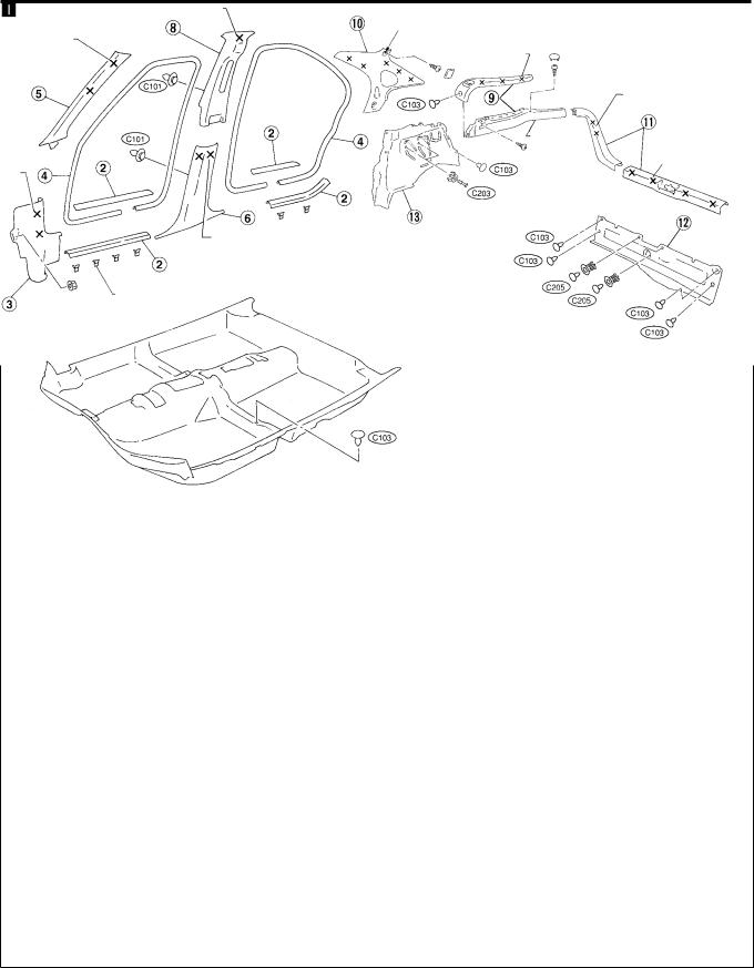
INTERIOR TRIM
Side and Floor Trim (Cont'd)
REMOVAL Ð Body side trim
5-door hatchback
●Remove parcel shelf before removing body side trim.
V |
Remove front and rear seats. Refer to ``SEAT'' for details, BT-40. |
|
1 |
|
|
V |
Remove front and rear kicking plates. |
|
2 |
|
|
V |
Remove dash side lower finishers. |
|
3 |
|
|
V |
Remove front and rear body side welts. |
|
4 |
|
|
V |
Remove front pillar garnishes. |
|
5 |
|
|
V |
Remove center pillar lower garnishes. |
|
6 |
|
|
V |
Remove front seat belt shoulder adjustment anchor bolt covers and anchor bolts (Refer to ``SEAT |
|
7 |
||
V |
BELTS'' in RS section for anchor bolt details). |
|
Remove center pillar upper garnishes. |
|
|
8 |
|
|
V |
Remove rear parcel shelf side finishers. |
|
9 |
|
|
V |
Remove rear pillar finishers. |
|
10 |
|
|
V |
Remove luggage room rear plate. |
|
11 |
|
|
V |
Remove luggage room rear finisher. |
|
12 |
|
|
V |
Remove luggage room side lower finishers. |
|
13 |
|
|
|
|
|
SEC. 678c749c769c799 |
|
|
|
Metal clips |
|
|
Metal clip |
|
Metal clip |
|
|
|
Metal clip |
|
|
|
Metal clip |
|
|
Metal clip |
Metal clip |
Metal clip |
|
|
||
|
Metal clip |
|
|
Metal clip |
|
X : Metal clips
NBT042
BT-20
Loading...