


DRIVESHAFTS
Exploded view
PK GEARBOX DRIVESHAFT
29 |
29-1

DRIVESHAFTS
Front driveshaft
SPECIAL TOOLING REQUIRED
T. Av. 476 Ball joint extractor
29 |
TIGHTENING TORQUES (in daNm) |
|
|
|
Shock absorber lower bolt |
18 |
Track rod end nut |
3.7 |
Hub nut |
28 |
Wheel bolt |
14.2 |
Mounting bolt on gearbox |
4.4 |
Mounting bolt on intermediate bracket |
4.4 |
Stud on gearbox |
0.8 |
|
|
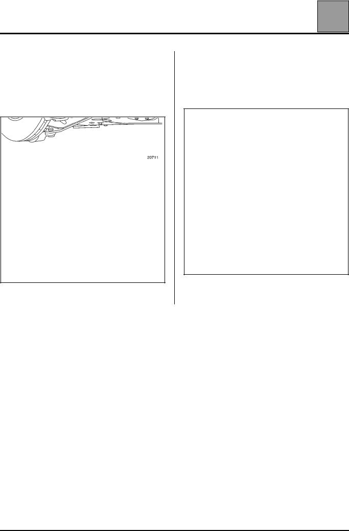
REMOVAL - WHEEL SIDE
Put the vehicle on a two-post lift.
Remove:
–the wheel hubcap,
–the hub nut,
–the front wheels,
Push the driveshaft back into the stub-axle carrier, whilst tilting the stub-axle carrier.
–the track rod end nut (B),
–the shock absorber lower mounting bolts (C).
29-2
DRIVESHAFTS Front driveshaft
29 |
REMOVAL - GEARBOX SIDE
Right-hand side
Remove:
–the two mounting bolts (A) of the intermediate support,
Left-hand side
Drain the gearbox.
Remove:
– the three gaiter mounting bolts on the gearbox,
– the driveshaft on the gearbox side.
– the driveshaft on the gearbox side.
29-3

DRIVESHAFTS Front driveshaft
29 |
REFITTING
Left-hand side
Remove the plastic protector from the bearing gaiter and insert the driveshaft as horizontally as possible.
The driveshaft should enter freely until the thread protrudes allowing the stub axle nut to be fitted.
Right-hand side
Clean the bore of the bearing into which the bearing is inserted.
Check the condition of the contact surface of the lip seal on the relay shaft.
NOTE: the differential output lip seal must always be replaced.
With the protector in place, coat the splines of the seal, gearbox end, with MOLYKOTE BR 2 grease.
Position the driveshaft and insert it.
The driveshaft should enter freely until the thread protrudes allowing the stub axle nut to be fitted.
Proceed in the reverse order to removal.
29-4
REAR AXLE
Bearing
33 |
SPECIAL TOOLING REQUIRED
T. Ar. 1623 Tool kit for replacing the rear bearings
REMOVAL |
NOTE: |
|
Remove: |
It is essential to fit a new bearing. |
|
REFITTING |
||
– the brake disc (refer to the relevant procedure), |
||
– the brake disc circlip. |
|
|
|
|
|
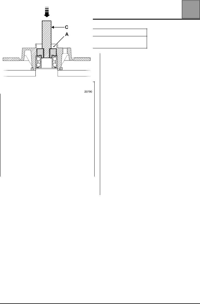
Refit: |
|
– the bearing using tools A and C. |
– the bearing using tools B and C, |
|
|
– |
the brake disc circlip, |
|
– |
the brake disc (refer to the relevant procedure). |
33-7
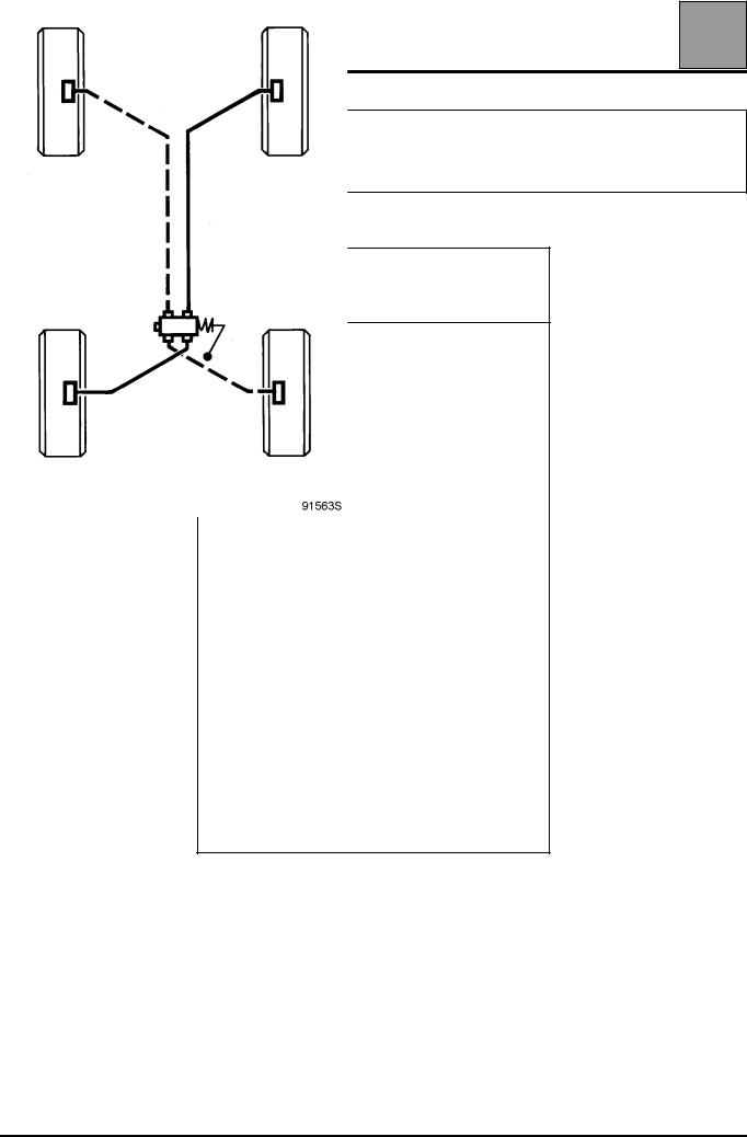
GENERAL INFORMATION General diagram of braking circuits
30 |
NOTE:
the diagram below shows the general principle; in no case should it be taken as reference for the circuit connections and allocations. When replacing one of the components of the brake circuit on a vehicle, always mark the pipes before removing them so that they can be connected back in their original positions.
"X" TYPE BRAKING
WITH load sensitive compensator
30-1
GENERAL INFORMATION
Brake unions and pipes
The connection of the pipes between the master cylinder, callipers, compensator, and hydraulic assembly is made by means of threaded unions with metric thread.
Consequently, only parts listed in the Parts Catalogue for this vehicle should be used.
Identification of parts:
–SHAPE of the steel or copper PIPE end piece (A),
–SHAPE of THREADED CASINGS on components (B),
–pipe UNIONS coloured GREEN or BLACK: external hexagon measuring 11 mm or 12 mm (C).
30 |
Brake fluid
BRAKE FLUID REPLACEMENT INTERVAL
Braking technology, in particular for disc brakes (hollow pistons which transfer little heat, low volume of fluid in the cylinder, sliding callipers avoiding the need for a fluid reservoir in the least cooled area of the wheel), has allowed us to avoid the risk of vapour lock as far as possible, even if the brakes are used intensively (in mountainous areas).
Modern brake fluids still degrade slightly during the first few months of use due to a small uptake of humidity and replacement of the fluid is therefore recommended (refer to vehicle's Servicing booklet).
Topping up the level
Wear of the brake pads and shoes will cause a gradual drop in the fluid level in the reservoir. This drop should not be compensated for since the level will rise again when the pads are changed. The level should not however be allowed to fall below the minimum mark.
Approved brake fluids:
Mixing two incompatible brake fluids in the circuit will cause a risk of major leaks, mainly due to deterioration of the cups. To avoid such risks, it is essential to keep to brake fluids which have been checked and approved by our laboratories and which conform to Standard SAE J 1703 dot 4.
For optimized use of vehicles equipped with an Electronic Stability Program, Nissan recommends a brake fluid with low viscosity in cold conditions (maximum 750 mm2/s at - 40°C).
30-2

GENERAL INFORMATION Dimensions of the main braking components
30 |
LUCAS FRONT BRAKES (mm) |
|
|
Slave cylinder diameter |
|
40-45 |
Disc diameter |
|
305 |
Disc thickness |
|
28 |
Minimum disc thickness |
|
24 |
Maximum run-out of discs |
|
0.07 |
Brake pad thickness (including mounting) |
|
18 |
Minimum thickness of brake pads (including mounting) |
|
9 |
|
|
|
LUCAS REAR BRAKES (mm) |
|
|
Diameter of brake cylinders |
|
41 |
Disc diameter |
|
280 |
Disc thickness |
|
12 |
Minimum disc thickness |
|
10 |
Maximum run-out of discs |
|
0.07 |
Brake pad thickness (including mounting) |
|
17 |
Minimum thickness of brake pads (including mounting) |
|
9 |
|
|
|
MASTER CYLINDER (mm) |
|
|
|
Left-hand drive |
25.4 x 36 |
X stroke diameter |
Right-hand drive |
20.6 x 52 |
|
Electronic Stability Program |
20.6 x 52 |
|
|
|
30-3

GENERAL INFORMATION Bleeding of the brake circuit (except ABS)
30 |
SPECIAL TOOLING REQUIRED
Brake circuit bleeding device
On vehicles fitted with a brake servo, it is important that the servo system is not actuated while the system is being bled, regardless of which method is being used to bleed the system.
The bleeding is done on a four-post lift, wheels on the ground.
Connect the bleeding device to the brake circuit bleed valves.
Start the bleeding device in accordance with its instruction manual.
Adjust the output pressure to 2 Bar.
This vehicle is fitted with an X-type braking circuit, so proceed as follows:
Open:
●the bleed screw of the rear right-hand wheel and let the fluid flow out for around 20 seconds,
●the bleed screw of the front left-hand wheel and let the fluid flow out for around 20 seconds.
Ignore the air bubbles in the pipes of the bleeding device.
Open:
●the bleed screw of the rear left-hand wheel and let the fluid flow out for around 20 seconds,
●the bleed screw of the front right-hand wheel and let the fluid flow out for around 20 seconds,
Check the firmness of the brake pedal when depressed (press several times).
Repeat the bleeding operation if necessary.
Top up the brake fluid level in the reservoir having disconnected the bleeding device.
Check the tightness of the bleed screws and that the sealing caps are all present.
The effectiveness and balance of the vehicle braking system may be checked on a suitable brake test bench.
(Refer to Section 38 for information on bleeding a braking circuit equipped with an Anti-lock Braking System).
30-4

GENERAL INFORMATION |
30 |
Specifications of the front anti-roll bars |
Rod diameter (mm) |
Marking colour |
|
|
22 |
none |
|
|
30-5
GENERAL INFORMATION Tightening torques (daNm)
30 |
BRAKE
CONTROL
Servo mounting nuts |
|
2.1 |
Master cylinder mounting nuts |
|
2.5 |
Master cylinder outlet pipes |
|
1.4 |
Compensator mounting bolt |
|
1.8 |
Compensator inlet pipes |
|
1.4 |
Compensator outlet pipes |
|
1.4 |
Hydraulic assembly mounting bolt |
|
0.9 |
Hydraulic assembly inlet pipes |
|
1.4 |
Hydraulic assembly outlet pipes |
|
1.4 |
|
|
|
|
|
|
FRONT |
|
|
|
|
|
Brake bleed screw, |
0.9 to 1.1 |
|
Calliper inlet pipes |
1.4 |
|
Brake calliper guide bolts |
10.5 |
|
Calliper mounting bolt |
3.5 |
|
|
|
|
|
|
|
REAR |
|
|
|
|
|
Brake bleed screw |
0.9 to 1.1 |
|
Calliper inlet pipes |
1.4 |
|
Brake calliper guide bolts |
18.0 |
|
Calliper mounting bolt |
3.3 |
|
Protective flange bolt |
0.8 |
|
|
|
|
AXLE ASSEMBLY
FRONT
Lower wishbone nut on sub-frame |
10.5 |
Sub-frame rear mounting bolt on the shell |
12 |
Sub-frame front mounting bolt on the angle |
10.5 |
frame |
|
Angle frame mounting bolt on the shell |
6.2 |
Lower wishbone bolt on sub-frame |
18.0 |
Anti-roll bar bearing nuts |
2.1 |
Lower ball joint nuts |
10.5 |
Wheel bolt |
14.2 |
Shock absorber base mounting bolt |
18.0 |
Driveshaft nut |
28.0 |
Shock absorber rod upper mounting bolts |
6.2 |
Shock absorber linkage mounting bolts |
4.4 |
|
|
|
|
REAR |
|
|
|
Shock absorber upper mounting bolt |
18 |
Shock absorber lower mounting bolt |
18 |
Fork mounting bolt on the shell |
10.5 |
Fork mounting bolt on the axle |
10.5 |
Wheel bolt |
14.2 |
Hub mounting bolt |
10.5 |
Hub nuts |
28.0 |
|
|
STEERING
STEERING COLUMN
Steering wheel mounting bolt |
4.4 |
Steering column upper mounting bolt |
2.1 |
|
|
|
|
STEERING RACK |
|
|
|
Steering rack mounting bolt |
18.0 |
Fork connection mounting bolt |
2.1 |
Steering ball joint nuts |
3.7 |
|
|
30-6

GENERAL INFORMATION Underbody height
30 |
VEHICLE |
At the front |
At the rear |
Dimension X (in mm) |
|
H1 - H2 =... mm |
H4 - H5 =... mm |
Left and right |
||
|
||||
|
|
|
|
|
FL0X |
49 |
14 |
- |
|
JL0X |
52 |
30 |
- |
|
|
|
|
|
|
Tolerance: ± 7.5 mm |
|
|
|
The difference between the right-hand side and the left-hand side of the same axle of a vehicle must not exceed 5 mm, the driver's side always being higher.
Any alteration to the underbody height also requires adjustment of the brake compensator and of the headlights.
30-7

GENERAL INFORMATION
Underbody height
MEASUREMENT POINTS
30 |
Measurements H1 and H4 are taken on the wheel shaft. Measurement H2 is taken under the jacking point. Measurement H5 is taken at the rear axle mounting shaft.
30-8

GENERAL INFORMATION
Influence of geometry
The influence of different geometry on tracking and vehicle tyre wear.
30 |
CAMBER
The comparison between the left and right-hand geometry is vital. A difference greater than one degree between the two sides will cause the direction to be offset, making steering wheel corrections necessary and causing excessive tyre wear.
The value of this geometry is usually small: in the region of 1°.
CASTOR
The comparison between the left and right-hand geometry is essential. A difference greater than one degree between the two sides will cause the direction to be offset, making steering wheel corrections necessary and causing excessive tyre wear.
This is characterised by drifting with the speed being stabilised on the side where the angle is smallest.
STEERING HEIGHT
This travel affects the wheel alignment variation during suspension travel.
Variations in alignment between the right hand and left hand wheels will lead to the following (with the steering wheel remaining in the same position):
–drift to one side under acceleration,
–drift to the other side under braking,
–track changes on uneven road surfaces.
WHEEL ALIGNMENT
This adjustment has little effect on the road holding.
Note:
–a significant toe-out excess leads to symmetrical wear on the inside of both tyres,
–a significant toe-in excess leads to symmetrical wear on the outside of both tyres.
30-9
GENERAL INFORMATION Geometry testing principle
30 |
PRELIMINARY CHECKS
Before checking the axle geometry, you must check the following points and remedy them if necessary:
–symmetry of the tyres on the same axle:
●dimensions,
●pressures,
●degree of wear.
–joints:
●condition of cushions and elastic bearings,
●ball joint gaps,
●bearing gaps.
–run-out of wheels: must not exceed 1.2 mm (it will be compensated for by the measuring equipment).
–symmetry of underbody heights (condition of the suspension).
DETERMINING THE STEERING CENTRE POINT
The steering centre point must be set before checking and adjusting the front axle in order to avoid drifting problems.
●Remove the ignition switch key.
●Straighten the wheels.
●Lock the steering: the centre point position is obtained.
Fit the measuring equipment with the wheels in this position and make the checks.
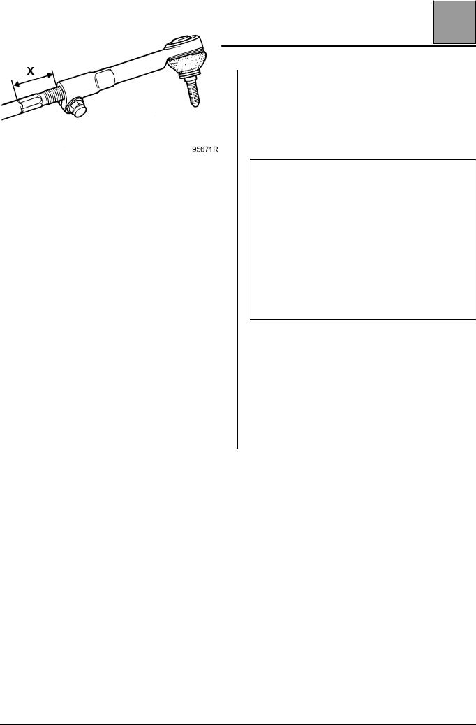
When adjusting the wheel alignment, be aware of the symmetry of the ball joint box X lengths with the steering links.
30-10

GENERAL INFORMATION Front axle checking and adjustment
30 |
CHRONOLOGICAL SEQUENCE OF OPERATIONS
Due to the geometric arrangement of the front axles, a modification of one of the angles (castor, camber, pivot, alignment and variation) has repercussions to a greater or lesser extent on the values of the other angles. (The castor angle is the one which has the greatest effect).
It is therefore essential to work in the following order:
–fit the equipment on the vehicle according to the manufacturer's instructions,
–locate the steering centre point (see preceding paragraph) and lock the steering wheel,
–raise the vehicle underbody,
–compensate for wheel rim run-out,
–place the vehicle on pivoting plates,
–fit the brake pedal press,
–adjust the suspension to bring the vehicle to its maximum height,
–check that the X lengths on the ball joint units are symmetrical with the steering links,
– plot the A values on the reading scale.
1Correct symmetry of X lengths:
–the dimension (A) must be evenly distributed.
2Incorrect symmetry of X lengths:
–plot the dimensions (A) on the right-hand and lefthand side, subtract them from one another and distribute the result with half on each side.
Example:
Right-hand side value: 16 Left-hand side value: 10 16 - 10 = 6
6:2 = 3
Adjust the steering links in order to balance the values
(A) of both sides:
A = 13
–once in this position, set the pivoting plates to zero,
–and check the following in sequence:
●castor,
●pivot,
●camber,
●wheel alignment.
30-11
GENERAL INFORMATION Front axle checking and adjustment
30 |
ADJUSTING THE WHEEL ALIGNMENT
There are several situations that can arise:
|
Alignment |
Distribution |
Correction to be made |
1 |
|
|
|
OK |
NOT OK |
Make the same number of turns with the adjuster (or sockets) |
|
|
|
|
but in the opposite direction on the left and right to get the |
|
|
|
same value (A) on both sides. |
2 |
NOT OK |
OK |
Set the alignment to the same value on the right and left, |
|
|
|
ensuring that the values (A) are always identical on both |
|
|
|
sides. |
3 |
NOT OK |
NOT OK |
Carry out an initial distribution in order to equalize values (A) |
|
|
|
on each side, then adjust the alignment as shown in example |
|
|
|
no. 2 |
|
|
|
|
Front axle fault finding
|
Faults |
Possible causes |
|
|
|
|
|
|
Incorrect castor |
– Bent arm |
|
|
|
– Bent side member or axle sub-frame |
|
|
|
|
|
|
Correct camber + pivot but |
– Bent arm |
|
|
Incorrect camber |
|
|
|
Incorrect pivot |
– Bent side member or axle sub-frame |
|
|
|
|
|
|
Correct camber |
|
|
|
but |
– Stub-axle carrier twisted |
|
|
Incorrect pivot |
|
|
|
|
|
|
|
Correct pivot |
|
|
|
but |
– Stub-axle carrier twisted |
|
|
Incorrect camber |
|
|
|
|
|
|
|
Alignment variation faults |
Bent arm |
|
|
– See castor |
|
|
|
|
Bent side member |
|
|
Incorrect alignment more than 6 mm |
– Right or left stub-axle carrier twisted |
|
|
|
|
|
30-12

GENERAL INFORMATION Brake fault finding
30 |
This fault finding procedure covers all types of circuit and braking components for the current range of vehicle not fitted with the Anti-lock Braking System.
For vehicles fitted with the Anti-lock Braking System, refer to Section 38.
Only those components belonging to the vehicles which are covered in this Workshop Repair Manual should be included in the fault finding procedure.
This fault finding procedure is produced in two separate parts, making it easier to find the relevant section.
ISymptom noted at the pedal
II Symptom noted in driving behaviour
ISYMPTOM NOTED AT THE PEDAL
Faults |
Possible causes |
|
|
Stiff pedal: |
– Servo-assistance failure |
substantial force produces poor deceleration |
– Brake shoes may be: |
|
|
|
– dirty, |
|
– glazed, incorrect type |
|
– which heat up under prolonged braking with the |
|
pedal constantly depressed (descending |
|
a mountain), not in good order |
|
– Piston seized |
|
– Crushed pipes |
|
|
Spongy pedal: |
– Presence of air in the circuit: incorrect bleeding |
NOTE: |
– Internal leak in the brake circuit |
The level of assistance on current vehicles has been |
|
improved meaning that it gives the impression of |
– Lack of fluid in the reservoir (from the brake circuit |
a spongy pedal. In order to find out whether this has |
leaking to the outside) |
arisen as a result of a fault or normal use, two tests must |
|
be carried out. |
|
1.Vehicle running
Subjective test: pedal travel / deceleration ratio
2.Vehicle stationary with the engine turned off
Additional test on pedal travel: press the brake pedal 5 times, to clear the brake servo, before taking account of the results of the test.
30-13

GENERAL INFORMATION Brake fault finding
30 |
|
Spongy pedal |
– Incorrectly adjusted shoes |
|
|
Test to be performed on a stationary vehicle with the |
Disc and drum brakes |
|
|
engine turned off |
Automatic adjustment: handbrake cable is too taut |
|
|
NOTE: |
|
|
|
NOTE: |
|
|
|
It is necessary to depress the brake pedal 5 times in |
|
|
|
order to clear the brake servo before taking account of |
Automatic compensation is operated via the brake |
|
|
the results of the test. |
pedal, if there is no abnormal tension in the handbrake |
|
|
|
cable when it is not in use. |
|
|
|
– Significant asymmetrical wear of brake shoes |
|
|
|
(convex or concave) |
|
|
|
– Excessive clearance in the master cylinder |
|
|
|
– Fluid at boiling point or overheated. |
|
|
|
|
|
|
Pedal to the floor |
– Hydraulic leak (check seal) |
|
|
Test to be performed on a stationary vehicle with the |
– Poor seal of the cup between two of the master |
|
|
engine turned off |
cylinder circuits |
|
|
NOTE: |
– Boiling fluid |
|
|
It is necessary to depress the brake pedal 5 times in |
|
|
|
order to clear the brake servo before taking account of |
|
|
|
the results of the test. |
|
|
|
|
|
|
II SYMPTOM NOTED IN DRIVING BEHAVIOUR |
|
|
|
|
|
|
|
|
Faults |
Possible causes |
|
|
|
|
|
|
Brakes engage |
– Lining needs grinding |
|
|
|
– Brake shoes are slightly dirty |
|
|
|
– Springs need to be changed |
|
|
|
|
|
|
Brakes judder |
– Drums out of round |
|
|
|
– Brake discs are too warped |
|
|
|
– Brake discs are not of even thickness |
|
|
|
– Abnormal deposit on the brake discs (oxidization |
|
|
|
between the brake shoe and the brake disc) |
|
|
|
|
|
30-14

GENERAL INFORMATION Brake fault finding
30 |
|
Drifting on braking (front) |
– Front axle suspension, check steering |
|
|
|
– Piston seized* |
|
|
|
– Tyres (wear - pressure) |
|
|
|
– Crushed pipes* |
|
|
|
*IMPORTANT: |
|
|
|
On vehicles with front axle with negative offset, pulling |
|
|
|
on one side affects the opposite circuit. |
|
|
|
|
|
|
Braking offset (rear) |
– Compensator or brake limiter (function control) |
|
|
|
– Piston seized |
|
|
|
– Incorrectly adjusted shoes |
|
|
|
Automatic adjustment: handbrake cable is too taut |
|
|
|
NOTE: |
|
|
|
Automatic compensation is operated via the brake |
|
|
|
pedal, if there is no abnormal tension in the handbrake |
|
|
|
cable when it is not in use |
|
|
|
– Recall spring |
|
|
|
|
|
|
Brakes heat up |
– Insufficient master cylinder clearance, which |
|
|
|
does not allow the master cylinder to return to its |
|
|
|
rest position |
|
|
|
– Seized or slow piston |
|
|
|
– Crushed pipes |
|
|
|
– Seized handbrake control |
|
|
|
– Poor adjustment of the handbrake control |
|
|
|
|
|
30-15
FRONT AXLE Brake pads
31 |
SPECIAL TOOLING REQUIRED
Fre. 823 Brake calliper piston return tool
TIGHTENING TORQUES (in daNm)
Wheel bolt |
14.2 |
Brake calliper mounting bolt (small |
|
column) |
3.5 |
|
|
|
|
REMOVAL
Remove:
–the front wheels,
–the lower calliper mounting bolts.
Loosen the upper calliper mounting bolts.
Unclip the brake pipes.
Turn the callipers upwards.
Remove the pads.
Check:
–the condition of the brake pads (if they need replacing, it is essential to change the pads on the opposite side as well),
–the condition and fitting of the piston dust covers,
–the condition of the dust seals of the guides,
–the condition of the brake discs.
Clean the calliper mountings and callipers.
REFITTING
Reinsert the pistons in the callipers using tool
Fre. 823.
Refit:
–the new brake pads,
–the callipers,
–the calliper mounting bolts,
–the brake pipes.
Tighten the calliper mounting bolts to the recommended torque.
Depress the brake pedal several times to bring the pistons into contact with the brake pads and discs.
Check the brake fluid level.
Refit the wheels.
Tighten the wheel bolts to the recommended torque.
31-1

FRONT AXLE Brake calliper
31 |
SPECIAL TOOLING REQUIRED
Fre. 823 Brake calliper piston return tool
TIGHTENING TORQUES (in daNm)
Calliper brake pipe |
1.4 |
Wheel bolt |
14.2 |
Brake calliper mounting bolt (small |
|
column) |
3.5 |
|
|
|
|
Depress the brake pedal using a pedal press (this has the effect of limiting the flow of brake fluid).
REMOVAL
Remove the front wheel.
Loosen the calliper brake pipe
Remove the calliper mounting bolts.
Disconnect the calliper and the brake pads.
Remove the calliper, turning it without twisting the hose.
Check:
–the condition of the hose and replace it if necessary,
–the condition of the brake pads (if they need replacing, it is essential to change the pads on the opposite side as well),
–the condition and fitting of the piston dust covers,
–the condition of the dust seals of the guides,
–the condition of the brake discs.
Clean the calliper mounting and the calliper.
REFITTING
Reinsert the pistons in the callipers using tool
Fre. 823.
Screw the calliper onto the hose without twisting the hose.
Refit:
–the brake pads,
–the calliper,
–the calliper mounting bolts,
Tighten to the recommended torque:
–the calliper mounting bolts,
–the hose.
Bleed the brake circuit (refer to the relevant procedure).
Depress the brake pedal several times to bring the pistons into contact with the brake pads and discs.
Check the brake fluid level.
Replace the front wheel.
Tighten the wheel bolts to the recommended torque.
31-2

FRONT AXLE Brake calliper mounting
31 |
SPECIAL TOOLING REQUIRED
Fre. 823 Brake calliper piston return tool
TIGHTENING TORQUES (in daNm)
Wheel bolt |
14.2 |
Brake calliper mounting bolt (small |
|
column) |
3.5 |
Calliper mounting bolt |
10.5 |
|
|
|
|
REMOVAL
Remove:
–the front wheel,
–the calliper mounting bolts,
Disconnect the calliper and the brake pads.
Suspend the calliper without bending the brake pipe.
Remove:
–the calliper mounting bolts,
–the calliper mounting.
Check:
–the condition of the hose and replace it if necessary,
–the condition of the brake pads (if they need replacing, it is essential to change the pads on the opposite side as well),
–the condition and fitting of the piston dust covers,
–the condition of the dust seals of the guides,
–the condition of the brake discs.
Clean the calliper and the mounting.
REFITTING
Reinsert the pistons in the callipers using tool
Fre. 823.
Refit:
–the calliper mounting,
–the brake calliper mounting bolts,
–the brake pads,
–the calliper,
–the calliper mounting bolts.
Tighten to the recommended torque:
–the brake calliper mounting bolts,
–the calliper bolts.
Depress the brake pedal several times to bring the pistons into contact with the brake pads and discs.
Check the brake fluid level.
Replace the front wheel.
Tighten the wheel bolts to the recommended torque.
31-3

FRONT AXLE Brake disc
31 |
SPECIAL TOOLING REQUIRED
Fre.823 Brake calliper piston return tool
TIGHTENING TORQUES (in daNm)
Wheel bolt |
14.2 |
Brake calliper mounting bolt (small |
|
column) |
3.5 |
Brake calliper mounting bolt |
10.5 |
Brake disc mounting bolt |
2.1 |
|
|
|
|
REMOVAL
Remove:
–the front wheel,
–the calliper mounting bolts.
Disconnect the calliper and the brake pads.
Suspend the calliper without bending the brake pipe.
Remove:
–the calliper mounting bolts,
–the calliper mounting,
–the brake disc mounting bolt,
–the brake disc.
Check:
–the condition of the hose and replace it if necessary,
–the condition of the brake pads (if they need replacing, it is essential to change the pads on the opposite side as well),
–the condition of the disc (if it needs replacing, it is essential to change the disc on the opposite side as well, plus the pads),
–the condition and fitting of the piston dust covers,
–the condition of the dust seals of the guides.
Clean the bearing surfaces of the brake disc, the calliper and the support.
REFITTING
Reinsert the piston in the callipers using tool Fre. 823.
Refit:
–the brake disc,
–the brake disc mounting bolt,
–the calliper mounting,
–the brake calliper mounting bolts,
–the brake pads,
–the calliper,
–the calliper mounting bolts.
Tighten to the recommended torque:
–the brake calliper mounting bolts,
–the calliper bolts.
Depress the brake pedal several times to bring the pistons into contact with the brake pads and discs.
Check the brake fluid level.
Refit the front wheel.
Tighten the wheel bolts to the recommended torque.
31-4

REAR AXLE Brake pads
33 |
SPECIAL TOOLING REQUIRED
Fre. 1190-01 Rear brake calliper piston return tool
TIGHTENING TORQUES (in daNm)
Wheel bolt |
14.2 |
Brake calliper bolt |
3.3 |
|
|
|
|
REMOVAL
Remove:
–the rear wheels,
–the upper calliper mounting bolts.
Unscrew the lower calliper mounting bolts.
Turn the callipers downwards.
Remove the brake pads from both sides of the vehicle.
Check:
–the condition and fitting of the piston dust covers,
–the condition of the guide dust covers,
–the brake discs.
Clean the calliper mountings and callipers.
REFITTING
Reinsert the pistons in the callipers using tool
Fre. 1190-01.
Refit:
–the new brake pads,
–the callipers,
–the calliper mounting bolts,
–the brake hoses.
Tighten the calliper bolts to the recommended torque.
Depress the brake pedal several times so that the pistons make contact with the pads.
Check the brake fluid level.
Refit the wheels.
Tighten the wheel bolts to the recommended torque.
33-1

REAR AXLE Brake calliper
33 |
SPECIAL TOOLING REQUIRED
Fre. 1190-01 Rear brake calliper piston return tool
TIGHTENING TORQUES (in daNm)
Calliper brake pipe |
1.4 |
Wheel bolt |
14.2 |
Brake calliper bolt |
3.3 |
Actuate the brake pedal using a pedal press (this has the effect of limiting the flow of brake fluid).
REMOVAL
Remove the rear wheel.
Separate the handbrake cable.
Loosen the brake pipe on the calliper side.
Unscrew the calliper mounting bolts.
Release the calliper and the brake pads.
Remove the calliper by turning it without twisting the hose.
Check:
–the condition of the hose and replace it if necessary,
–the condition of the brake pads (if they need replacing, it is essential to replace the pads on the opposite side as well),
–the condition and fitting of the piston dust covers,
–the condition of the guide dust covers,
–the brake discs.
Clean the calliper mountings and callipers.
REFITTING
Reinsert the calliper pistons using tool Fre. 1190-01.
Screw the calliper onto the hose without twisting the hose.
Refit:
–the brake pads,
–the calliper,
–the calliper mounting bolts,
–the handbrake cable.
Tighten to the recommended torque:
–the calliper mounting bolts,
–the hose.
Bleed the brake circuit (refer to the relevant method).
Check the travel of the handbrake control lever.
Refit the rear wheel.
Tighten the wheel bolts to the recommended torque.
33-2

REAR AXLE Brake calliper mount
33 |
SPECIAL TOOLING REQUIRED
Fre. 1190-01 Rear brake calliper piston return tool
TIGHTENING TORQUES (in daNm)
Wheel bolt |
14.2 |
Brake calliper bolt |
3.3 |
Brake calliper mounting bolt |
18 |
|
|
|
|
REMOVAL
Remove:
–the rear wheel,
–the calliper mounting bolts,
Disconnect the calliper and the brake shoes.
Suspend the calliper without bending the hose.
Remove the calliper mounting bolts.
Remove the calliper mounting.
Check:
–the condition of the hose and replace it if necessary,
–the condition of the brake pads (if they need replacing, it is essential to replace the pads on the opposite side as well),
–the condition and fitting of the piston dust covers,
–the condition of the guide dust covers,
–the brake discs.
Clean the calliper mounting and the calliper.
REFITTING
Reinsert the calliper pistons using tool Fre. 1190-01.
Refit:
–the calliper support,
–the calliper support bolts,
–the brake shoes,
–the calliper,
–the calliper mounting bolts,
Tighten to the recommended torque:
–the calliper support bolts,
–the calliper support bolts,
Refit the rear wheel.
Tighten the wheel bolts to the recommended torque.
33-3

REAR AXLE Brake discs
33 |
SPECIAL TOOLING REQUIRED
Fre. 1190-01 Rear brake calliper piston return tool
TIGHTENING TORQUES (in daNm)
Hub nut |
28 |
Wheel bolt |
14.2 |
Brake calliper bolt |
3.3 |
Brake calliper mounting bolt |
18 |
|
|
|
|
REMOVAL
Remove the calliper support (consult the relevant procedure).
Remove:
–the hub nut,
–the disc.
Check:
–the condition of the hose and replace it if necessary,
–the condition of the brake pads (if they need replacing, it is essential to replace the pads on the opposite side as well),
–the condition of the disc (if it needs replacing, it is essential to replace the disc on the opposite side as well, plus the pads),
–the condition and fitting of the piston dust covers,
–the condition of the guide dust covers.
Clean the bearing surfaces of the brake disc, the calliper and the support.
REFITTING
Reinsert the calliper pistons using tool Fre. 1190-01.
Refit:
–the disc,
–the calliper support,
–the calliper support bolts,
–the brake pads,
–the calliper,
–the calliper mounting bolts,
Tighten to the recommended torque:
–the hub nut,
–the calliper support bolts,
–the calliper support bolts,
Refit the rear wheels.
Tighten the wheel bolts to the recommended torque.
33-4

REAR AXLE
Brake disc protective flange bolt
33 |
TIGHTENING TORQUE (in daNm)
Flange mounting bolt |
0.8 |
REMOVAL
Remove:
– the brake disc (refer to the relevant procedure),
REFITTING
Refit:
–the flange,
–the three flange mounting bolts.
Tighten the three flange mounting bolts to the correct torque.
Refit the brake disc (refer to the relevant procedure).
–the three flange mounting bolts,
–the flange.
33-5

REAR AXLE Rear brake disc hub
33 |
TIGHTENING TORQUE (in daNm)
Hub mounting bolt |
10.5 |
REMOVAL
Remove:
–the brake disc protective flange (consult the relevant procedure),
REFITTING
Refit:
–the hub,
–the four hub mounting bolts,
Tighten the four hub mounting bolts to the correct torque.
Refit the brake disc protective flange (consult the relevant procedure),
–the four hub mounting bolts,
–the hub.
33-6
 Loading...