


ENGINE
[SUPPLEMENT]
PF series
PF6TB AND PF6TC
Pub.No. SSM615PFE2

HOW TO USE THIS MANUAL
+This supplement is designed to provide you with the new service procedures, service data and specifications for the PF6TB engine on the CKB457/459, CWB457/459 and CGB457 models and PF6TC engine on the CKB45A, CWB45A, CGB45A models.
+However, this supplement contains only new service procedures and relevant data, etc.
For information which is not included in this manual, refer to the general service manual mentioned below. Service Manual: PF series ``MODELS PF6, PF6T, PF6TA & PF6TB'' (Pub. No. SMEPFS2E00)
+Please be sure to follow the instruction below when using this supplement.
1)See the specified section titles in the QUICK REFERENCE INDEX of this supplement, and check whether the background is black or white.
2) Only those items containing supplementary information are specified in the CONTENTS of each section.
Ð 1 Ð

6n053for |
0001DRD-1225-4-S(M) |
6n053for
White:
No change. Please refer to the engine service manual PF series ``MODELS PF6, PF6T, PF6TA & PF6TB'' (Pub. No. SMEPFS2E00).
Black:
Service procedures and service data have been added.
Only the new or revised information is described.
-1-1

GENERAL
CONTENTS
SPECIFICATIONS ..................................... |
GE-1- 1 |
ENGINE SPECIFICATIONS ........................ |
GE-1- 1 |
SUPPLEMENTAL OUTLINE
+Addition of specifications due to introduction of the PF6TB-21 engine in the CKB, CWB and CGB457 series.
+Addition of specifications due to introduction of the PF6TB-22 engine in the CKB459 and CWB459 series.
+Addition of specifications due to introduction of the PF6TC engine in the CKB, CWB and CGB45A series.

SPECIFICATIONS
SPECIFICATIONS
ENGINE SPECIFICATIONS
Item |
|
|
|
|
|
Engine model |
PF6TB-21 |
|
PF6TB-22 |
|
PF6TC |
|
|
|
|
|
|
|
|
|
|||||
|
|
|
|
|
|
|
|
|
|
|
||
|
|
|
|
|
|
|
|
|
|
|||
Max. output (SAE) |
|
|
|
kW {PS}/rpm |
257 {350}/2,100 |
|
279 {380}/2,100 |
|||||
|
|
|
|
|
|
|
|
|
|
|
|
|
Type |
|
|
|
|
|
|
|
|
Diesel |
|
||
|
|
|
|
|
|
|
|
|
|
|||
Aspiration system |
|
|
|
|
|
Turbocharger with intercooler |
||||||
|
|
|
|
|
|
|
|
|
|
|
||
Cooling method |
|
|
|
|
|
|
Water cooled |
|
||||
|
|
|
|
|
|
|
|
|
|
|
||
Number of cylinders and cylinder arrangement |
|
|
|
|
6, in-line |
|
||||||
|
|
|
|
|
|
|
|
|
|
|
|
|
Stroke cycle |
|
|
|
|
|
|
4 |
|
|
|||
|
|
|
|
|
|
|
|
|
|
|
||
Combustion chamber |
|
|
|
|
|
|
Direct fuel injection |
|
||||
|
|
|
|
|
|
|
|
|
|
|
||
Valve mechanism |
|
|
|
|
|
|
Overhead |
|
||||
|
|
|
|
|
|
|
|
|
|
|
|
|
Cylinder liner |
|
|
|
|
|
|
|
Dry |
|
|||
|
|
|
|
|
|
|
|
|
|
|
||
Bore x stroke |
|
|
|
|
mm (in) |
|
133.0 x 150.0 (5.24 x 5.91) |
|||||
|
|
|
|
|
|
|
|
|
|
|
||
Total displacement |
|
|
|
cm3 (cu in) |
|
12,503 (763) |
|
|
||||
Compression ratio |
|
|
|
|
|
16.5 |
|
|
||||
|
|
|
|
|
|
|
|
|
|
|
||
Cylinder compression |
|
|
kPa {kgf/cm2, psi}/rpm |
|
3,040 {31, 441}/200±20 |
|
||||||
Max. engine speed under full load conditions |
|
|
|
2,480 |
|
2,300 |
||||||
|
|
|
|
|
|
|
|
|
|
|
|
|
Idle speed |
|
|
|
|
|
430 - 530 |
|
550 - 570 |
|
510 - 610 |
||
|
|
|
|
|
|
|
|
|
|
|
|
|
Number of piston rings |
|
Compression ring |
|
2 |
|
|
||||||
|
|
|
|
|
|
|
|
|
||||
|
Oil ring |
|
|
|
1 |
|
|
|||||
|
|
|
|
|
|
|
|
|
|
|||
|
|
|
|
|
|
|
|
|
|
|
|
|
|
|
|
|
|
Intake |
|
Open (B.T.D.C.) |
|
16° |
|
|
|
|
|
|
|
|
|
|
|
|
|
|
|
|
Valve timing |
|
|
|
Closed (A.B.D.C.) |
|
20° |
|
|
||||
|
|
|
|
|
|
|
||||||
|
|
|
|
|
|
|
|
|
|
|||
|
|
Exhaust |
|
Open (B.B.D.C.) |
|
52° |
|
|
||||
|
|
|
|
|
|
|
|
|
||||
|
|
|
|
|
|
|
|
|
|
|
|
|
|
|
|
|
|
|
Closed (A.T.D.C.) |
|
12° |
|
|
||
|
|
|
|
|
|
|
|
|
|
|||
|
|
|
|
|
|
|
|
|
|
|
|
|
|
|
Valve clearance |
|
Intake |
|
|
|
0.30 - 0.40 (0.012 - 0.016) |
||||
|
|
mm (in) |
|
|
|
|
|
|
|
|
||
|
|
|
|
Exhaust |
|
|
|
0.30 - 0.40 (0.012 - 0.016) |
||||
|
|
|
|
|
|
|
|
|
|
|
|
|
|
|
Lubrication system |
|
|
|
|
|
Forced-circulation type |
|
|||
|
|
|
|
|
|
|
|
|
|
|
|
|
|
|
|
|
Type |
|
|
|
|
Gear pump |
|
||
|
|
|
|
|
|
|
|
|
|
|
|
|
|
|
Oil pump |
|
Discharge amount |
|
! (Imp gal)/rpm |
|
174 (38-1/4)/2,300 |
|
|
||
|
|
|
|
|
|
|
|
|
|
|
|
|
|
|
|
|
Relief valve opening pressure |
|
1,177 {12.0, 171} |
|
|
||||
|
|
|
|
|
|
|
kPa {kgf/cm2, psi} |
|
|
|
||
system |
|
|
|
Type |
Full-flow |
|
|
|
|
Paper element type |
|
|
|
|
|
|
|
|
|
|
|
|
|
||
|
|
|
|
By-pass |
|
|
|
|
Paper element type |
|
||
|
|
|
|
|
|
|
|
|
|
|||
|
|
Oil filter |
|
|
|
|
|
|
|
|
|
|
Lubrication |
|
|
Replacement method |
|
|
|
|
Disassembly type |
|
|||
|
|
|
|
|
|
|
|
|||||
|
|
|
|
|
|
|
|
|
|
|
|
|
|
|
Short valve opening pressure |
|
98 - 137 {1.0 - 1.4, 14 - 20} |
||||||||
|
|
|
|
|
|
|
kPa {kgf/cm2, psi} |
|
||||
|
|
|
|
Type |
|
|
|
Water cooled flat tube type |
||||
|
|
|
|
|
|
|
|
|
|
|
|
|
|
|
Oil cooler |
|
Number of cores |
|
|
|
5 |
|
|
||
|
|
|
|
|
|
|
|
|
|
|
|
|
|
|
|
|
Short valve opening pressure |
|
304 - 343 {3.1 - 3.5, 44 - 50} |
||||||
|
|
|
|
|
|
|
kPa {kgf/cm2, psi} |
|
||||
|
|
Regulator valve opening pressure |
|
kPa {kgf/cm2, psi} |
|
392 - 432 {4.0 - 4.4, 57 - 63} |
||||||
|
|
|
|
System total capacity |
|
|
|
29 (6-3/8) |
|
|
||
|
|
Lubrication oil ca- |
|
|
|
|
|
|
|
|
|
|
|
|
|
H-level |
|
|
|
21 (4-5/8) |
|
|
|||
|
|
pacity |
! (Imp gal) |
Oil pan |
|
|
|
|
|
|||
|
|
|
|
|
|
|
|
|
|
|||
|
|
L-level |
|
|
|
14 (3-1/8) |
|
|
||||
|
|
|
|
|
|
|
|
|
|
|||
|
|
|
|
|
|
|
|
|
|
|
|
|
GE-1-1

SPECIFICATIONS
Item |
|
|
|
|
Engine model |
|
PF6TB-21 |
|
PF6TB-22 |
|
PF6TC |
|
|
|
|
|
|
|
|
|
|
||||
|
|
|
|
|
|
|
|
|
|
|
|
|
|
|
|
|
|
|
|
|
|
|
|
||
|
Cooling system |
|
|
|
|
|
|
Water cooled, forced circulation |
||||
|
|
|
|
|
|
|
|
|
|
|
|
|
|
Radiator type |
|
|
|
|
|
|
|
|
Corrugated fin |
|
|
|
|
|
|
|
|
|
|
|
|
|
|
|
|
Cooling fan |
Number of fins |
|
|
|
|
|
6 |
|
|
||
|
|
|
|
|
|
|
|
|
|
|
|
|
|
|
Type |
|
|
|
|
|
ON-OFF type (FD2000-C) |
|
Linear type |
||
|
|
|
|
|
|
|
|
(FDL2300) |
||||
system |
Fan clutch |
|
|
|
|
|
|
|
|
|
|
|
|
|
|
|
|
|
|
|
|
|
|
||
Changeover temperature |
|
°C (°F) |
60 - 70 (140 - 158) |
|
60±10 - 75±5 |
|||||||
|
|
|
||||||||||
|
|
|
(140±18 - 167±9) |
|||||||||
|
|
|
|
|
|
|
|
|
|
|
||
|
|
|
|
|
|
|
|
|
|
|
|
|
Cooling |
|
Type |
|
|
|
|
|
|
|
Centrifugal |
|
|
|
|
|
|
|
|
|
|
|
|
|
|
|
Water pump |
Drive |
|
|
|
|
|
|
|
Gear drive |
|
||
|
|
|
|
|
|
|
|
|
|
|
|
|
|
Number of impellers |
|
|
|
|
|
6 |
|
|
|||
|
|
|
|
|
|
|
|
|
||||
|
|
|
|
|
|
|
|
|
|
|
|
|
|
|
Type |
|
|
|
|
|
|
|
Wax pellet |
|
|
|
Thermostat |
|
|
|
|
|
|
|
|
|
|
|
|
Valve opening temperature |
|
|
|
|
76.5 (170) - 1 |
|
|
||||
|
|
|
|
|
|
|
|
|||||
|
|
|
|
|
°C (°F) - Number |
|
|
|
|
|||
|
|
|
|
|
|
|
|
|
|
|||
|
|
|
|
|
|
|
|
|
|
|
|
|
|
Cooling water capacity |
|
|
! (Imp gal) |
|
|
|
37 (8-1/8) |
|
|
||
|
|
|
|
|
|
|
|
|
|
|
|
|
|
Ignition system |
|
|
|
|
|
|
Compression ignition |
|
|||
|
|
|
|
|
|
|
|
|
|
|
|
|
|
Fuel injection timing (B.T.D.C.) |
|
|
|
|
|
3° |
|
2° |
|
0° |
|
|
|
|
|
|
|
|
|
|
|
|
|
|
|
Ignition order |
|
|
|
|
|
|
|
|
1-4-2-6-3-5 |
|
|
|
|
|
|
|
|
|
|
|
|
|
|
|
|
Fuel filter |
|
Main |
|
|
|
|
|
Cartridge type |
|
||
|
|
|
|
|
|
|
|
|
|
|
|
|
|
|
Primary |
|
|
|
|
|
Center bolt type |
|
|||
|
|
|
|
|
|
|
|
|
||||
|
|
|
|
|
|
|
|
|
|
|
|
|
|
|
|
Type |
|
|
|
|
|
Bosch |
|
||
|
|
|
|
|
|
|
|
|
|
|
|
|
system |
Fuel injection pump |
|
Plunger diameter |
mm (in) |
|
|
|
12.0 (0.472) |
|
|
||
|
|
|
|
|
|
|
|
|
|
|
||
|
Governor |
|
|
|
Electrical RED-III type |
|
||||||
|
|
|
|
|
|
|||||||
|
|
|
|
|
|
|
|
|
|
|
|
|
|
|
Timer |
|
|
|
Centrifugal (Mechanical SDG type) |
||||||
Fuel |
|
|
|
|
|
|||||||
|
|
|
|
|
|
|
|
|
|
|
||
|
|
Nozzle holder |
|
|
|
|
Flange type |
|
||||
|
|
|
|
|
|
|
|
|
|
|
|
|
|
|
|
Nozzle type |
|
|
|
|
|
Multi-hole type |
|
||
|
|
|
|
|
|
|
|
|
|
|
|
|
|
Fuel injection nozzle |
|
Nozzle |
|
Number |
|
|
6 |
|
|
7 |
|
|
|
|
|
|
|
|
|
|
|
|
||
|
|
|
holder |
|
Diameter |
mm (in) |
0.31 (0.0122) [K4] |
|
0.27 (0.0106) [K6] |
|
0.26 (0.0102) [K8] |
|
|
|
|
|
|
|
|
||||||
|
|
|
|
|
|
|
|
|
|
|
||
|
|
|
Valve opening pressure |
|
22,556 {230, 3,271} |
|
|
|||||
|
|
|
|
|
kPa {kgf/cm2, psi} |
|
|
|
||||
|
Overflow valve opening pressure |
Injection pump outlet |
|
|
|
|
255 {2.6, 37} |
|
|
|||
|
kPa {kgf/cm2, psi} |
Fuel filter |
|
|
|
108 - 147 {1.1 - 1.5, 16 - 21} |
||||||
|
|
|
|
|
|
|
|
|
|
|
||
|
Air cleaner |
|
|
|
|
|
|
Paper element (Dry: Dual type) |
||||
|
|
|
|
|
|
|
|
|
|
|
|
|
system |
|
|
Model |
|
|
|
TD45 |
|
GT45 |
|
GT42 |
|
|
|
|
|
|
|
|
|
|
|
|
||
|
|
|
|
|
|
Radial-flow turbine |
|
|
|
|
||
|
|
Turbine type |
|
|
(With variable |
|
Radial-flow turbine |
|||||
|
|
|
|
|
|
|
plate) |
|
|
|
|
|
exhaust |
Turbocharger |
|
|
|
|
|
|
|
|
|
|
|
|
|
|
|
|
|
|
|
|
|
|
||
|
Compressor type |
|
|
|
|
Centrifugal |
|
|||||
|
|
|
|
|
|
|
||||||
|
|
|
|
|
|
|
|
|
|
|
|
|
|
|
Lubrication method |
|
|
Engine oil circulation type |
|||||||
and |
|
|
|
|
||||||||
|
|
|
|
|
|
|
|
|
|
|
||
|
|
Bearing type |
|
|
|
|
Full floating |
|
||||
intake |
|
|
|
|
|
|
|
|
|
|
|
|
Intercooler |
|
Type |
|
|
|
|
|
Air to air |
|
|||
|
|
|
|
|
|
|
|
|
|
|
||
|
Intercooler |
|
|
|
|
|
Corrugated fin |
|
||||
|
|
|
|
|
|
|
|
|||||
Air |
|
|
|
|
|
|
|
|
||||
|
|
|
|
|
|
|
|
|
|
|
|
|
Exhaust shutter |
|
Type |
|
|
|
|
|
Cylinder |
|
|||
|
|
|
|
|
|
|
|
|||||
|
|
|
|
|
|
|
|
|
|
|
|
|
|
|
Operation |
|
|
|
|
|
Air |
|
|||
|
|
|
|
|
|
|
|
|
||||
|
|
|
|
|
|
|
|
|
|
|
|
|
GE-1-2

SPECIFICATIONS
Item |
|
|
|
Engine model |
PF6TB-21 |
PF6TB-22 |
|
PF6TC |
|
|
|
|
|
||||
|
|
|
|
|
|
|
|
|
|
|
|
|
|
|
|
|
|
|
|
Type |
|
|
|
Shift |
|
|
|
|
|
|
|
|
|
|
|
|
Starting motor |
Model |
|
|
0350 602 0381 |
350 602 0460 |
||
|
|
|
|
|||||
|
|
|
0350 602 0460 |
|||||
|
|
|
|
|
|
|
|
|
|
|
|
|
|
|
|
|
|
|
|
Output |
|
V-kW |
|
24-6.0 |
|
|
|
|
|
|
|
|
|
|
|
|
|
Type |
|
|
|
AC, diode-rectified |
||
|
|
|
|
|
|
|
|
|
system |
|
|
|
|
0202 102 1943 |
|
|
|
|
Model |
|
|
|
0201 152 1130 |
|
0201 102 4510 |
|
|
|
|
0202 152 0044 |
|||||
|
|
|
|
|
|
|
||
|
|
|
|
(0202 152 0043) |
|
|
|
|
|
|
|
|
|
|
|
|
|
Electrical |
Alternator |
|
|
0202 102 1943 |
24-40 |
|
|
|
|
|
|
|
Ð |
|
Ð |
||
|
|
0202 152 0044 |
24-50 |
|
||||
|
|
|
|
|||||
|
|
|
|
|
|
|||
|
Output |
V-A |
(0202 152 0043) |
|
|
|
||
|
|
|
|
|
||||
|
|
|
|
0201 152 1130 |
Ð |
24-50 |
|
Ð |
|
|
|
|
|
|
|
|
|
|
|
|
|
0201 102 4510 |
Ð |
Ð |
|
24-40 |
|
|
|
|
|
|
|
|
|
|
|
Regulator |
|
|
|
IC-transistor type |
|
|
|
|
|
|
|
|
|
|
|
|
|
Type |
|
|
|
Ribbon |
|
|
|
|
|
|
|
|
|
|
|
|
Air heater |
Voltage (V) x Current (A) - Number |
|
11.0 x 85 - 2 |
|
|
||
|
|
|
|
|
|
|
|
|
|
|
Model |
|
|
|
F9560W12 |
|
|
|
|
|
|
|
|
|
|
|
equipment |
|
Theoretical discharge |
cm3 (cu in) |
|
425 (26) |
|
|
|
Air compressor |
Normal maximum discharge pressure |
|
834 {8.5, 121} |
|
|
|||
|
|
kPa {kgf/cm2, psi} |
|
|
|
|||
|
Cooling system |
|
|
Water cooled (Forced circulation type) |
||||
Auxiliary |
|
|
|
|||||
|
|
|
|
|
|
|
|
|
Vacuum pump |
Type |
|
|
Vane |
|
Ð |
||
|
|
|
|
|
|
|
||
Model |
|
|
VD-30 |
|
Ð |
|||
|
|
|
|
|||||
|
|
|
|
|
|
|
|
|
GE-1-3

MAINTENANCE
CONTENTS
SERVICE DATA .......................................... |
MA-1- 1 |
SERVICE DATA .......................................... |
MA-1- 1 |
TIGHTENING TORQUE ............................. |
MA-1- 2 |
TOOLS ........................................................... |
MA-2- 1 |
MAINTENANCE PROCEDURE ............ |
MA-3- 1 |
SUPPLEMENTAL OUTLINE
BASIC MECHANICAL SYSTEM ................. |
MA-3- 1 |
|
FAN CLUTCH ............................................. |
MA-3- 1 |
|
FUEL SYSTEM ........................................... |
MA-3- |
2 |
INTAKE AND EXHAUST SYSTEM ............. |
MA-3- |
5 |
+Addition of service data and maintenance procedure due to introduction of a new vehicle model.
+The fuel injection timing has been changed.
+The idle speed has been changed.
+The tightening torque of the injection pump coupling mounting bolt has been changed.
+Addition of fuel injection timing and idle speed maintenance standards for the PF6TB-22 and PF6TC engines.
+Addition of a model GT42, 45 turbocharger.

SERVICE DATA
SERVICE DATA
SERVICE DATA
|
|
|
|
|
|
|
|
Unit: mm (in) |
|
Item |
|
|
Maintenance standard |
Service limit |
Remarks |
||
|
|
|
|
|
|
|
|
|
|
|
Intake |
|
|
0.30 |
- 0.40 |
Ð |
|
|
|
|
|
(0.012 |
- 0.016) |
|
||
|
Valve clearance |
|
|
|
|
When engine is cold |
||
|
|
|
|
|
|
|
||
system |
Exhaust |
|
|
0.30 |
- 0.40 |
Ð |
||
|
|
|
|
|||||
|
|
|
(0.012 |
- 0.016) |
|
|||
|
|
|
|
|
|
|||
|
|
|
|
|
|
|
||
|
|
|
|
|
|
|
|
|
mechanical |
|
Intake |
Open |
|
16° B.T.D.C. |
Ð |
|
|
|
|
|
|
|
|
|
||
Valve timing |
Closed |
|
20° A.B.D.C. |
Ð |
|
|||
|
|
|
||||||
|
|
|
|
|||||
|
|
|
|
|
|
|
|
|
|
Exhaust |
Open |
|
52° B.B.D.C. |
Ð |
|
||
|
|
|
|
|||||
|
|
|
|
|
|
|
|
|
Basic |
|
Closed |
|
12° A.T.D.C. |
Ð |
|
||
|
|
|
|
|||||
|
|
|
|
|
|
|
||
Cylinder compression pressure |
|
|
3,040 {31, 441} |
1,961 {20, 284} |
At 180 to 220 rpm |
|||
|
|
|
|
|
|
|||
|
|
kPa {kgf/cm2, psi} |
|
|
|
|
(With engine warm) |
|
|
Compression pressure difference |
|
Less than 392 {4, 57} |
Ð |
|
|||
|
|
kPa {kgf/cm2, psi} |
|
|
||||
|
|
|
|
|
|
|
||
|
Water tank cap operating pressure |
|
49 |
- 69 |
Ð |
Pressure side |
||
|
|
kPa {kgf/cm2, psi} |
|
{0.5 - 0.7, 7 - 10} |
||||
|
|
|
|
|
||||
|
|
|
|
|
|
|
|
|
|
|
Fan pulley |
|
|
8 - 12 (0.31 - 0.47) |
Ð |
|
|
system |
|
- Tension pulley |
|
With a force of about |
||||
|
|
|
|
|
||||
Deflection of V-belt |
Idler (cooler compres- |
|
|
|
|
98 N {10 kgf, 22 lbf} |
||
|
|
|
|
|
||||
Cooling |
|
sor) pulley |
|
|
15 - 18 (0.59 - 0.71) |
Ð |
applied to the mid part |
|
|
- Alternator pulley |
|
|
|
|
|
||
|
|
|
|
|
|
|
||
|
|
|
|
|
|
|
|
|
|
|
Valve opening tem- |
|
74.5 |
- 78.5 |
73.0 - 80.0 |
|
|
|
Thermostat |
perature |
°C (°F) |
(166 |
- 173) |
(163 - 176) |
|
|
|
|
|
|
|
|
|
|
|
|
Valve lift/temperature |
More than |
More than |
|
||||
|
|
|
||||||
|
|
mm/°C (in/°F) |
10/90 (0.39/194) |
8.5/90 (0.335/194) |
|
|||
|
|
|
|
|
|
|
|
|
|
|
PF6TB-21 |
|
|
|
3° |
Ð |
|
|
Fuel injection timing |
|
|
|
|
|
|
|
system |
PF6TB-22 |
|
|
|
2° |
Ð |
|
|
B.T.D.C. |
|
|
|
|
|
|
|
|
|
PF6TC |
|
|
|
0° |
Ð |
|
|
|
|
|
|
|
|
|||
|
|
|
|
|
|
|
|
|
Fuel |
|
PF6TB-21 |
|
|
430 |
- 530 |
Ð |
|
Idle speed |
|
|
|
|
|
|
|
|
PF6TB-22 |
|
|
550 |
- 570 |
Ð |
|
||
|
rpm |
|
|
|
||||
|
PF6TC |
|
|
510 |
- 610 |
Ð |
|
|
|
|
|
|
|
||||
|
|
|
|
|
|
|
|
|
MA-1-1
SERVICE DATA
TIGHTENING TORQUE
|
|
|
|
|
|
|
Unit: N´m {kgfzm, ftzlbf} |
|
|
|
Item |
|
Tightening torque |
Remarks |
|||
|
|
|
|
|
|
|
|
|
|
Valve clearance adjusting screw lock nut |
|
34 - 44 |
{3.5 - 4.5, 25 - 33} |
|
|||
|
|
|
|
|
|
|
||
|
|
Snug torque (1st) |
|
88 - 98 {9.0 - 10.0, 65 - 72} |
|
|||
system |
Cylinder head |
|
|
|
|
|
|
|
angle (2nd) |
|
L = 119 mm (4.69 in) |
|
70° - 80° |
|
|||
|
|
|
|
|||||
|
bolt |
Tightening |
|
L = 147 mm (5.79 in) |
|
85° - 95° |
|
|
mechanical |
|
|
|
|
|
|
|
|
Cylinder head |
1st |
|
|
|
34 {3.5, 25} |
|
||
|
|
|
|
|
||||
|
sub bolt |
2nd |
|
|
44 - 54 |
{4.5 - 5.5, 33 - 40} |
|
|
|
|
|
|
|
|
|
|
|
Basic |
Air intake manifold mounting bolt and nut |
|
49 - 54 |
{5.0 - 5.5, 36 - 40} |
|
|||
|
|
|
|
|
|
|
|
|
Exhaust manifold mounting nut |
|
|
29 - 44 |
{3.0 - 4.5, 22 - 33} |
|
|||
|
|
|
|
|||||
|
|
|
|
|
|
|
|
|
|
Crank damper mounting bolt |
|
|
98 - 108 {10.0 - 11.0, 72 - 80} |
|
|||
|
|
|
|
|
|
|
|
|
|
Compression gauge bolt |
|
|
25 - 29 |
{2.5 - 3.0, 18 - 22} |
|
||
|
|
|
|
|
|
|
|
|
system |
Oil pan drain plug |
|
|
98 - 127 {10.0 - 13.0, 72 - 94} |
|
|||
|
|
|
|
|
|
|
|
|
|
Full-flow type |
|
Center bolt |
|
59 - 69 |
{6.0 - 7.0, 43 - 51} |
|
|
|
|
|
|
|
||||
Lubrication |
|
|
|
|
|
|
|
|
|
|
Drain plug |
|
16 - 22 |
{1.6 - 2.2, 12 - 16} |
|
||
|
Oil filter |
|
|
Drain plug |
|
16 - 22 |
{1.6 - 2.2, 12 - 16} |
|
|
|
|
|
|
|
|
|
|
|
Bypass type |
|
Center bolt |
|
59 - 69 |
{6.0 - 7.0, 43 - 51} |
|
|
|
|
|
|
|
||||
|
|
|
|
|
|
|
|
|
|
|
|
|
|
|
|
|
|
|
|
|
|
|
|
|
|
|
|
Injection pump |
Coupling bolt and nut |
|
103 - 113 |
{10.5 - 11.5, 76 - 83} |
|
||
|
drive coupling |
Cotter bolt |
|
|
147 - 167 {15.0 - 17.0, 108 - 123} |
|
||
|
|
|
|
|
|
|
|
|
|
Injection nozzle retaining nut |
|
|
59 - 78 |
{6.0 - 8.0, 43 - 58} |
|
||
system |
|
|
|
|
|
|
|
|
Nozzle holder assembly mounting bolt |
|
Apply film of engine oil to gasket and |
|
|||||
|
|
25 - 29 |
{2.5 - 3.0, 18 - 22} |
|
||||
Fuel |
|
Cartridge type |
|
|
screw on until gasket contacts en- |
|
||
|
|
|
|
|
||||
|
|
|
|
gine, then tighten 3/4 turn by hand |
|
|||
|
|
|
|
|
|
|
||
|
Fuel filter |
|
|
|
|
or UD genuine filter wrench |
|
|
|
|
|
|
|
|
|
|
|
|
|
Bypass type |
|
Center bolt |
|
59 - 69 |
{6.0 - 7.0, 43 - 51} |
|
|
|
|
|
|
|
|
|
|
|
|
|
Drain plug |
|
16 - 22 |
{1.6 - 2.2, 12 - 16} |
|
|
|
|
|
|
|
|
|||
|
|
|
|
|
|
|
|
|
|
|
|
|
Turbine housing and center housing |
17.0 {1.73, 12.5} → Loosen → |
|
||
|
|
|
|
mounting V-band lock nut |
|
|||
|
|
|
|
13.7 {1.40, 10.1} |
|
|||
|
|
|
|
|
N´m {kgfzm, ftzlbf} |
|
||
|
|
Model TD45 |
|
|
|
|
|
|
|
|
|
|
|
|
|
|
|
system |
|
|
Compressor housing and back plate |
|
|
|
||
|
|
|
|
|
|
|||
|
|
|
|
N´m {kgfzm, ftzlbf} |
9.0 - 11.3 {0.92 - 1.15, 6.7 - 8.3} |
|
||
|
|
|
|
clamp mounting bolt |
|
|||
exhaust |
|
|
|
|
|
|
|
|
|
|
|
Turbine housing and center housing |
|
|
|
||
|
|
|
|
|
|
|
||
|
Turbocharger |
|
|
mounting V-band lock nut |
12.7 - 14.7 |
{130 - 150, 113 - 130} |
|
|
and |
Model GT45 |
|
|
N´m {kgfzcm, inzlbf} |
|
|
|
|
|
|
|
|
|
|
|||
|
|
|
Compressor housing and back plate |
|
|
|
||
intake |
|
|
|
10.3 - 12.3 {105 - 125, 91 - 109} |
|
|||
|
|
|
mounting bolt |
N´m {kgfzcm, inzlbf} |
|
|||
|
|
|
|
|
||||
|
|
|
|
|
|
|
||
|
|
|
|
|
|
|
|
|
Air |
|
|
|
Turbine housing and center housing |
|
|
|
|
|
|
|
mounting V-band lock nut |
12.7 - 14.7 |
{130 - 150, 113 - 130} |
|
||
|
|
|
|
|
||||
|
|
Model GT42 |
|
|
N´m {kgfzcm, inzlbf} |
|
|
|
|
|
|
|
Compressor housing and back plate |
10.3 - 12.3 {105 - 125, 91 - 109} |
|
||
|
|
|
|
mounting bolt |
N´m {kgfzcm, inzlbf} |
|
||
|
|
|
|
|
|
|
||
|
|
|
|
|
|
|
|
|
MA-1-2

TOOLS
TOOLS
Tool name and number |
Description |
Shape |
|
|
|
Feeler gauge |
For adjusting valve clearance |
|
99541 Z5000 |
Thickness mm (in) |
|
|
0.25 (0.0098), 0.3 (0.012), 0.35 (0.0138), 0.4 |
|
|
(0.016), 0.45 (0.0177), 0.5 (0.020) |
|
|
|
ET14-049 |
|
|
|
Feeler gauge |
For adjusting valve clearance |
|
99541 Z0001 |
Thickness mm (in) |
|
|
0.2 (0.008), 0.3 (0.012), 0.4 (0.016) |
|
|
|
ET14049A |
|
|
|
Timing plate |
For measuring valve timing |
|
99646 Z5001 |
|
|
|
ZMA121A |
|
|
|
ET14-053 |
|
|
|
Adapter |
Used when measuring valve timing as a set includ- |
|
99808 96500 |
ing the timing plate (99646 Z5001) |
|
|
|
WMA148A |
|
|
|
Compression gauge |
For measuring compression pressure |
|
99640 96000 |
|
|
|
|
ET14050B |
|
|
|
Compression gauge hose |
Used with the compression gauge (99640 96000) |
|
99644 97000 |
when the gauge cannot be installed directly due to |
|
|
interference with the air duct, etc. |
|
|
|
ET14-051 |
|
|
|
MA-2-1

TOOLS
Tool name and number |
Description |
Shape |
|
|
|
Plate |
For fixing nozzle holder |
|
157944-9520 |
NOTE |
|
|
+ Tool number designated by ZEXEL CORPO- |
|
|
RATION |
|
|
|
WMA001A |
|
|
|
Pin vice |
For cleaning nozzle orifice |
|
99727 Z5005 |
|
|
|
|
EP14-121 |
|
|
|
Nozzle cleaner |
For removal of carbon from rear of nozzle orifice |
|
99726 Z5000 |
|
|
|
|
ET14-072 |
|
|
|
Filter wrench |
For removal of fuel filter |
|
99755 00Z01 |
(Only when replacing cartridge type element) |
|
|
|
WMA027A |
|
|
|
MA-2-2

MAINTENANCE PROCEDURE
MAINTENANCE PROCEDURE
BASIC MECHANICAL SYSTEM
VALVE CLEARANCE
Procedure for checking valve timing
1.Remove the V-belt, cooling fan and crank pulley assembly.
2.Turn the flywheel in the normal direction until the No. 1 piston is at the top dead center on the compression stroke.
NOTE
+If the flywheel has been rotated excessively, rotate it backwards beyond the desired position then gradually rotate it back in the normal direction until it is set in the proper position.
3.Attach the timing plate (99646 Z5001) and adapter (99808 96500) to the end of the crankshaft. Also attach a needle pointer utilizing the front cover mounting bolt, and align the needle to ``0''.
4.Set a dial gauge so that the contact arm is in contact with the upper valve spring seats of the intake valve and exhaust valve.
FAN CLUTCH
|
|
|
|
Unit: C° (F°) |
|
|
Item |
Run the engine |
Operating temperatures |
|
|
|
continuously |
||||
|
|
|
|
||
|
|
|
|
|
|
FDL2300-C |
|
Linear type |
2,300 rpm |
60±10 - 75±5 |
|
|
|
||||
|
|
|
|
(140±18 - 167±9) |
|
EP12-3
WMA149A
MA-3-1
MAINTENANCE PROCEDURE
FUEL SYSTEM
INJECTION TIMING
1.Remove the pointer cover. Secure the pointer to the flywheel housing using bolts.
2.Crank the engine in the standard direction by turning the flywheel with a lever until the pointer is aligned with the timing mark.
NOTE
+If the mark goes past the pointer, move it back past the pointer and turn again in the standard direction until alignment is made.
Item |
Maintenance standard |
Service limit |
||
|
|
|
|
|
|
PF6TB-21 |
3° |
Ð |
|
Fuel injection timing |
|
|
|
|
PF6TB-22 |
2° |
Ð |
||
(B.T.D.C.) |
||||
|
|
|
||
PF6TC |
0° |
Ð |
||
|
||||
|
|
|
|
|
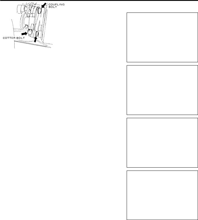
3.If the timer marks are not aligned as shown in the figure, adjust as follows:
Adjustment of fuel injection timing
1.Make sure the pointer points to the specified injection timing graduation on the outer periphery of the flywheel and loosen the coupling bolts (2 places).
2.Back the timer off a little in the reverse direction of the normal timer direction. Turn the timer in the normal direction to adjust the pointer to the mark.
3.Tighten the coupling bolts and cotter bolt.
Coupling bolt and nut
 : 103 - 113 N´m {10.5 - 11.5 kgfzm, 76 - 83 ftzlbf}
Cotter bolt
 : 147 - 167 N´m {15.0 - 17.0 kgfzm, 108 - 123 ftzlbf}
WDR151A
WDR167A
EP4-23
EMA1002E
MA-3-2

MAINTENANCE PROCEDURE
IDLE SPEED
NOTE
+When checking engine idle speed ensure that the engine idle control knob inside the cab is set to the low-speed position.
1.Start the engine and warm it up to the normal operating temperature.
2.Allow the engine to idle and observe the engine speed on the tachometer.
3.If idle speed is not within specified range, adjust as follows:
NOTE
+If equipped with an air conditioner, the air conditioner switch must be turned off when checking idle speed.
|
|
|
|
Unit: rpm |
|
Item |
Maintenance standard |
Service limit |
|
|
|
|
|
|
|
|
PF6TB-21 |
430 - 530 |
Ð |
|
|
|
|
|
Idle speed |
|
PF6TB-22 |
550 - 570 |
Ð |
|
|
|
|
|
|
|
PF6TC |
510 - 610 |
Ð |
|
|
|
|
|
Idle speed adjustment
1.Loosen the lock nut on the idle adjusting bolt.
2.Turn the idle adjusting bolt to obtain the correct idle speed.
3.Tighten the lock nut on the idle adjusting bolt.
NOTE
+Accelerate the engine two or three times. Allow the engine to return to idle speed and observe the tachometer reading. If the idle speed is not within the specified range, check the accelerator linkage for binding and repeat idle adjustment.
NOZZLE (INJECTOR PRESSURE AND PATTERN)
Cleaning nozzle
1.Remove the nozzle holder assembly from the engine. Refer to the ``ENGINE DISASSEMBLY AND REASSEMBLY'' section for details.
2.Clamp the nozzle holder in a vise with a holder plate (1579449520).
3.Loosen the retaining nut, and then remove the nozzle from the nozzle holder. Do not drop the nozzle needle.
EEF1160A
MA-3-3

MAINTENANCE PROCEDURE
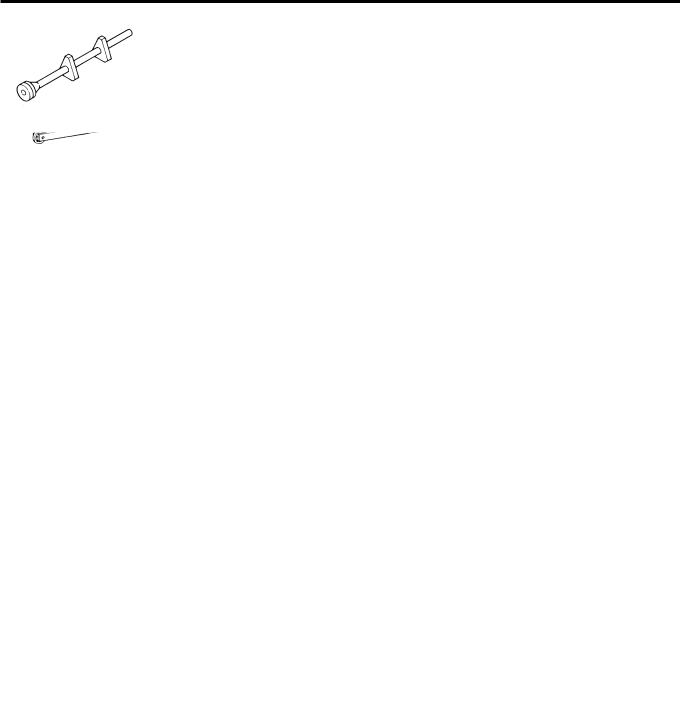
4. Pull the nozzle needle from the nozzle body.
NOTE
+ Do not use the nozzle needle in another nozzle body.
5.Remove carbon from around the openings by using the corner of a hard piece of wood. Do not use waste or any other material to push carbon into the openings.
6.Removing carbon in openings
Use the pin vice (99727 Z5005) and wire to clean the openings.
|
|
|
Unit: mm (in) |
|
Nozzle identifica- |
Number of injec- |
Injection nozzle |
Wire diameter |
|
tion mark |
tion nozzle holes |
hole diameter |
||
|
||||
|
|
|
|
|
K4 |
6 |
0.31 (0.0122) |
0.29 (0.0114) |
|
|
|
|
||
K6 |
0.27 (0.0106) |
0.26 (0.0102) |
||
|
||||
|
|
|
|
|
K8 |
7 |
0.26 (0.0102) |
0.25 (0.0098) |
|
|
|
|
|
+Allowing too much wire to protrude at the tip of the holder will permit the wire to bend inside the nozzle, in which case withdrawal proves difficult. The wire should protrude no more than 2.0 to 2.5 mm (0.079 to 0.098 in).
+Carefully push the carbon into the nozzle. Too much force will bend the wire. Proceed slowly.
+Remove carbon at the inside end of the openings with the nozzle cleaner (99726 Z5000).
Exercise care to avoid damaging the surface which the nozzle
needle contacts. The use of compressed air may clog the openings with foreign particles.
7.Tighten the retaining nut.
 : 59 - 78 N´m {6.0 - 8.0 kgfzm, 43 - 58 ftzlbf}
WMA017A
WMA018A
WMA019A
MA-3-4

MAINTENANCE PROCEDURE
INTAKE AND EXHAUST SYSTEM
TURBOCHARGER
NOTE
+Before attempting any servicing of the turbocharger, clean its entire exterior surface.
+Never use a caustic solution. Caustic solutions attack aluminum.
To clean the compressor side
1.Remove the turbocharger from the engine.
2.Remove the compressor housing and check the condition of the impeller (compressor wheel). If it is not excessively dirty, clean the impeller and the inner surface of the housing with a brush and a cloth dampened with diesel fuel.
CAUTION
+ Do not use a wire brush or scraper.
3.If the impeller is excessively dirty, overhaul and clean. Refer to the ENGINE ``IE'' section for cleaning instructions.
4.When the impeller is wet with cleaning solvent, dry with compressed air.
CAUTION
+Hold the impeller by hand to prevent it from turning while drying.
5. Install the compressor housing in its original position.
 : Model TD45
9.0 - 11.3 N´m {0.92 - 1.15 kgfzm, 6.7 - 8.3 ftzlbf}
 : Model GT42, 45
10.3 - 12.3 N´m {105 - 125 kgfzcm, 91 - 109 inzlbf}
To clean the turbine side
1.Remove the turbine housing and check the condition of the turbine. If the turbine is not excessively dirty, clean the turbine and the inner surface of the turbine housing in a manner similar to that outlined under ``To clean the compressor side''.
2.If the turbine is excessively dirty, overhaul and clean.
3.When the impeller is wet with cleaning solvent, dry with compressed air.
CAUTION
+Hold the impeller with your hand to prevent it from turning while cleaning.
4. Install the turbine housing in its original position.
 : Model TD45
17.0 N´m {1.73 kgfzm, 12.5 ftzlbf}
→Loosen
→13.7 N´m {1.40 kgfzm, 10.1 ftzlbf}
: Model GT42, 45
12.7- 14.7 N´m {130 - 150 kgfzcm, 113 - 130 inzlbf}
5.Check that the turbine wheel rotates smoothly by your hand. Install the turbocharger on the engine and check for gas or air leakage.
MA-3-5

ENGINE DISASSEMBLY
AND REASSEMBLY
CONTENTS
SERVICE DATA .......................................... |
DR-1- 1 DISASSEMBLY |
|
|
TIGHTENING TORQUE .............................. |
DR-1- 1 |
AND REASSEMBLY ................................. |
DR-4- 1 |
TOOLS ........................................................... |
DR-2- 1 |
OUTSIDE OF ENGINE ............................... |
DR-4- 1 |
CONSTRUCTION ....................................... |
DR-3- 1 |
ENGINE PROPER ...................................... |
DR-4- 4 |
ENGINE ....................................................... |
DR-3- 1 |
|
|
SUPPLEMENTAL OUTLINE
+ Addition of tightening torque due to introduction of a new vehicle model.

SERVICE DATA
SERVICE DATA
TIGHTENING TORQUE
|
|
|
|
|
|
|
Unit: N´m {kgfzm, ftzlbf} |
|
|
|
|
|
|
||
|
|
Item |
|
Tightening torque |
Remarks |
||
|
|
|
|
|
|
|
|
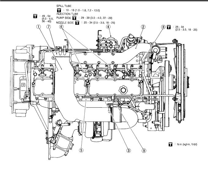
Nozzle holder assembly mounting bolt |
|
25 - 34 |
{2.5 - 3.5, |
18 - 25} |
|
||
|
|
|
|
|
|
||
Spill tube mounting bolt |
|
|
10 - 18 {1.0 - 1.8, 7.2 - 13.0} |
|
|||
|
|
|
|
|
|
|
|
Injection tube |
|
Pump side |
|
29 - 39 |
{3.0 - 4.0, |
22 - 29} |
|
|
|
|
|
|
|
|
|
|
Nozzle side |
|
25 - 34 |
{2.5 - 3.5, |
18 - 25} |
|
|
|
|
|
|
||||
|
|
|
|
|
|
|
|
Fuel tube and fuel return tube |
|
25 - 29 |
{2.5 - 3.0, |
18 - 22} |
|
||
|
|
|
|
|
|
||
Crank pulley mounting bolt |
|
|
177 - 196 {18.0 - 20.0, 130 - 145} |
|
|||
|
|
|
|
|
|
||
Fan pulley mounting bolt |
|
|
186 - 196 {19.0 - 20.0, 137 - 145} |
|
|||
|
|
|
|
|
|
|
|
Cooling fan mounting nut |
|
|
16 - 19 |
{1.6 - 1.9, |
12 - 14} |
|
|
|
|
|
|
|
|
|
|
Hydraulic pump drive gear mounting nut |
|
59 - 78 |
{6.0 - 8.0, |
43 - 58} |
|
||
|
|
|
|
|
|
|
|
Alternator mounting bolt |
|
|
59 - 78 |
{6.0 - 8.0, |
43 - 58} |
|
|
|
|
|
|
|
|
||
Oil pan drain plug |
|
|
98 - 127 {10.0 - 13.0, 72 - 94} |
|
|||
|
|
|
|
|
|
|
|
Exhaust manifold mounting nut |
|
29 - 44 |
{3.0 - 4.5, |
22 - 33} |
|
||
|
|
|
|
|
|
|
|
Oil outlet pipe mounting bolt |
|
|
13 - 14 {1.30 - 1.45, |
9.4 - 10.5} |
|
||
|
|
|
|
|
|
|
|
Oil inlet tube connector bolt |
|
|
13 - 14 {1.30 - 1.45, |
9.4 - 10.5} |
|
||
|
|
|
|
|
|
|
|
Oil cooler housing mounting bolt and nut |
Bolt |
29 - 54 |
{3.0 - 5.5, |
22 - 40} |
|
||
|
|
|
|
|
|||
Nut |
54 - 93 |
{5.5 - 9.5, |
40 - 69} |
|
|||
|
|
|
|
||||
|
|
|
|
|
|
|
|
Turbocharger mounting bolt |
|
|
34 - 44 |
{3.5 - 4.5, |
25 - 33} |
|
|
|
|
|
|
|
|
|
|
Air intake manifold mounting nut |
|
49 - 54 |
{5.0 - 5.5, |
36 - 40} |
|
||
|
|
|
|
|
|
|
|
Air compressor mounting bolt |
|
30 - 41 |
{3.1 - 4.2, |
22 - 30} |
|
||
|
|
|
|
|
|
||
Starting motor mounting bolt |
|
|
69 {7.0, 51} |
|
|||
|
|
|
|
|
|
|
|
Injection pump bracket mounting bolt |
|
30 - 41 |
{3.1 - 4.2, |
22 - 30} |
|
||
|
|
|
|
|
|
|
|
Injection pump mounting bolt |
|
48 - 62 |
{4.9 - 6.3, |
35 - 46} |
|
||
|
|
|
|
|
|
|
|
Injection pump coupling |
|
Coupling bolt |
|
103 - 113 |
{10.5 - 11.5, 76 - 83} |
|
|
mounting bolt |
|
Cotter bolt |
|
147 - 167 {15.0 - 17.0, 108 - 123} |
|
||
|
|
|
|
|
|
||
Injection pump oil tube |
|
Feed side |
|
10 - 18 {1.0 - 1.8, 7.2 - 13.0} |
|
||
|
|
|
|
|
|
|
|
|
|
Pump side |
15 - 34 |
{1.5 - 3.5, |
11 - 25} |
|
|
connector |
|
Return side |
|
||||
|
|
|
|
|
|
||
Block side |
25 - 41 |
{2.5 - 4.2, |
18 - 30} |
|
|||
|
|
|
|
||||
|
|
|
|
|
|||
Engine mounting bracket mounting bolt |
|
98 - 127 {10.0 - 13.0, 72 - 94} |
|
||||
|
|
|
|
|
|
|
|
Engine lifter mounting bolt |
|
|
74 - 93 |
{7.5 - 9.5, |
54 - 69} |
|
|
|
|
|
|
|
|
|
|
Cylinder head sub bolt |
|
1st |
|
34 {3.5, 25} |
|
||
|
|
|
|
|
|
||
|
2nd |
44 - 54 |
{4.5 - 5.5, |
33 - 40} |
|
||
|
|
|
|
||||
|
|
|
|
|
|
||
|
|
Snug torque (1st) |
88 - 98 {9.0 - 10.0, 65 - 72} |
|
|||
|
|
|
|
|
|
|
|
Cylinder head bolt |
|
Tightening |
L = 147 mm (5.79 in) |
|
85° - 95° |
|
|
|
|
angle (2nd) |
L = 119 mm (4.69 in) |
|
70° - 80° |
|
|
|
|
|
|
|
|
|
|
Rocker shaft bracket mounting bolt |
|
34 - 49 |
{3.5 - 5.0, |
25 - 36} |
|
||
|
|
|
|
|
|
|
|
DR-1-1
SERVICE DATA
|
|
|
|
|
Unit: N´m {kgfzm, ftzlbf} |
|
|
|
|
|
|
Item |
|
|
Tightening torque |
Remarks |
|
|
|
|
|
|
|
Oil jet connector bolt |
|
|
29 - 39 {3.0 - 4.0, 22 - 29} |
|
|
|
|
|
|
|
|
Main bearing cap bolt |
|
265 |
- 294 {27.0 - 30.0, |
195 - 217} |
|
|
|
|
|
|
|
Connecting rod cap nut |
|
230 |
- 245 {23.5 - 25.0, |
170 - 181} |
|
|
|
|
|
|
|
Front gear case mounting bolt |
|
|
25 - 34 {2.5 - 3.5, 18 - 25} |
|
|
|
|
|
|
|
|
Injection pump drive gear mounting nut |
|
392 |
- 441 {40.0 - 45.0, |
289 - 325} |
|
|
|
|
|
|
|
Camshaft gear mounting nut |
|
245 |
- 265 {25.0 - 27.0, |
181 - 195} |
|
|
|
|
|
|
|
Camshaft locating plate mounting bolt |
|
|
20 - 24 {2.0 - 2.4, 14 - 17} |
|
|
|
|
|
|
|
|
Cam chamber cover mounting bolt |
|
|
15 - 29 {1.5 - 3.0, 11 - 22} |
|
|
|
|
|
|
|
|
Idler gear mounting bolt |
|
|
18 - 22 {1.8 - 2.2, 13 - 16} |
|
|
|
|
|
|
|
|
Idler gear shaft bolt |
|
|
49 - 57 {5.0 - 5.8, 36 - 42} |
|
|
|
|
|
|
|
|
Air compressor drive gear mounting nut |
|
186 |
- 206 {19.0 - 21.0, |
137 - 152} |
|
|
|
|
|
|
|
Oil pump mounting bolt |
|
|
30 - 41 {3.1 - 4.2, 22 - 30} |
|
|
|
|
|
|
|
|
Oil screen and oil outlet pipe mounting bolt |
|
16 - 21 {1.6 - 2.1, 12 - 15} |
|
||
|
|
|
|
||
Flywheel housing mounting bolt |
M12 |
78 - 98 {8.0 - 10.0, 58 - 72} |
|
||
|
|
|
|
|
|
Stiffener mounting bolt |
Housing side |
|
74 - 88 {7.5 - 9.0, 54 - 65} |
|
|
|
|
|
|
|
|
Block side |
98 |
- 137 {10.0 - 14.0, |
72 - 101} |
|
|
|
|
||||
|
|
|
|
|
|
Oil pan mounting bolt |
|
|
21 {2.1, 15} |
|
|
|
|
|
|
|
|
Flywheel mounting bolt |
|
255 |
- 304 {26.0 - 31.0, |
188 - 224} |
|
|
|
|
|
||
Crank damper mounting bolt |
|
98 - 108 {10.0 - 11.0, 72 - 80} |
|
||
|
|
|
|
|
|
Rear PTO idler shaft mounting bolt |
|
|
127 {13.0, 94} |
|
|
|
|
|
|
|
|
Engine rear PTO companion flange nut |
|
392 |
- 412 {40.0 - 42.0, |
289 - 304} |
|
|
|
|
|
|
|
DR-1-2
TOOLS
TOOLS
Tool name and number |
Description |
Shape |
|
|
|
Engine stand |
For disassembling and reassembling engine proper |
|
99550 96001 |
|
|
Head assembly |
|
|
99551 96001 |
|
|
|
|
ET14-001 |
|
|
|
Engine stand attachment |
For disassembling and reassembling engine proper |
|
99554 96001 |
To be used together with engine stand |
|
|
|
EDR1074A |
|
|
|
Piston insert tool |
For inserting piston into cylinder |
|
99631 96502 |
|
|
|
|
ET14045C |
|
|
|
Injection pump bracket |
For centering of injection pump bracket |
|
setting tool |
|
|
99720 95500 |
|
|
|
|
ETL2-003 |
|
|
|
DR-2-1

CONSTRUCTION
CONSTRUCTION
ENGINE
WDR148A
DR-3-1
DISASSEMBLY AND REASSEMBLY
DISASSEMBLY AND REASSEMBLY
OUTSIDE OF ENGINE
UPPER SIDE OF ENGINE
WDR149A
Disassembly sequence (Reassembly sequence is the reverse of disassembly.)
j1 |
Air intake duct |
j4 |
Fuel filter |
j7 |
Air intake manifold |
j2 |
Air intake |
j5 |
Water manifold |
j8 |
Nozzle holder assembly |
j3 |
Water tube |
j6 |
Nozzle tube |
j9 |
PCM valve |
DR-4-1

DISASSEMBLY AND REASSEMBLY
RIGHT SIDE OF ENGINE
WDR150A
Disassembly sequence (Reassembly sequence is the reverse of disassembly.)
j1 |
Air intake duct |
j5 |
Turbocharger |
j9 |
Car heater pipe |
j2 |
Exhaust outlet |
j6 |
Exhaust manifold |
j10 |
Oil filter |
j3 |
Exhaust shutter |
j7 |
Water duct |
j11 |
Oil cooler |
j4 |
Air pipe |
j8 |
Water pump |
|
|
DR-4-2

DISASSEMBLY AND REASSEMBLY
LEFT SIDE OF ENGINE Key points of reassembly
j4 Injection pump
When the injection pump bracket has been removed, center it using the following procedure:
1.Fasten the injection pump bracket.
 : 30 - 41 N´m {3.1 - 4.2 kgfzm, 22 - 30 ftzlbf}
2.Centering the injection pump bracket
Set a bracket setting tool (99720 95500) in place. Then check to make sure that the shaft of the injection pump support enters the hole on the end of the shaft smoothly.
3.If it does not enter smoothly, adjust by changing the thickness of the injection pump bracket shims.
Shim thickness [mm (in)]: 0.05 (0.0020)
:0.10 (0.0039)
:0.20 (0.0079)
4.Install the injection pump.
 : 48 - 62 N´m {4.9 - 6.3 kgfzm, 35 - 46 ftzlbf}
5.Turn the flywheel in the standard direction of rotation to align the scribed line of the injection timer on the No. 1 cylinder with the pointer. If not aligned properly, rotate the flywheel in the reverse direction sufficiently, and realign.
Item |
Maintenance standard |
Service limit |
||
|
|
|
|
|
Fuel injection |
PF6TB-21 |
3° |
Ð |
|
|
|
|
||
PF6TB-22 |
2° |
Ð |
||
timing (B.T.D.C.) |
||||
PF6TC |
0° |
Ð |
||
|
||||
|
|
|
|
|
EDR1151A
WDR008A
WDR151A
WDR167A
DR-4-3
DISASSEMBLY AND REASSEMBLY
6.Align the mark on the injection pump with the scribed line on the timer, then connect the coupling.
Unit: N´m {kgfzm, ftzlbf}
Item |
Tightening torque |
|
|
|
|
Coupling bolt |
103 - 113 {10.5 - 11.5, 76 |
- 83} |
|
|
|
Cotter bolt |
147 - 167 {15.0 - 17.0, 108 |
- 123} |
|
|
|
ENGINE PROPER
Key points of reassembly
1.Attach the engine stand attachment (99554 96001), then raise the cylinder block using a crane or other devices, and mount it on the engine stand (99550 96001).
2.Install the oil jet.
 : 29 - 39 N´m {3.0 - 4.0 kgfzm, 22 - 29 ftzlbf}
3. Install the main bearing upper shell.
NOTE
+Be sure to install the main bearing upper shell in the original position before disassembly.
EMA1002E
EP3-30
EN3-065
ZDR025A
DR-4-4

DISASSEMBLY AND REASSEMBLY
4.Attach the upper thrust washer to both side of the No. 7 main bearing and measure the end play of the crankshaft. If the measured value exceeds the service limit, replace the thrust washer with a new one.
|
|
|
|
|
Unit: mm (in) |
|
Maintenance standard |
Service limit |
|
|
|||
|
|
|
|
|
|
|
0.05 - 0.14 (0.0020 - 0.0055) |
0.5 (0.020) |
|
|
|||
|
|
|
|
|
|
|
|
|
|
|
|
Unit: mm (in) |
|
|
A |
3.995 - 4.025 (0.1573 - 0.1585) |
|
|
|
|
|
|
|
|
|
||
|
B |
3.970 - 4.000 (0.1563 - 0.1575) |
|
Standard |
||
|
|
|
|
|
|
|
Thrust washer |
C |
3.945 - 3.975 (0.1553 - 0.1565) |
|
|
|
|
|
|
|
|
|
|
|
|
0.15 O.S. |
4.100 - 4.150 (0.1614 - 0.1634) |
O.S.: Oversize |
|||
|
|
|
|
|||
|
0.30 O.S. |
4.250 - 4.300 (0.1673 - 0.1693) |
||||
|
|
|
|
|||
|
|
|
|
|
|
|
NOTE
+Be sure the oil groove side of the thrust washer faces toward the crankshaft.
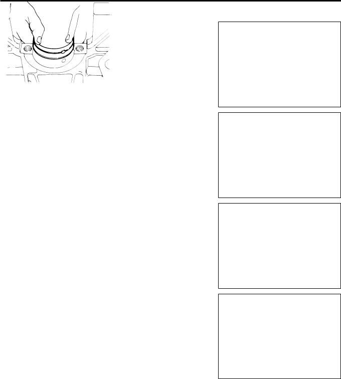
5.Fit the main bearing lower shell into the main bearing cap, and install the main bearing cap. Install the lower thrust washer onto both sides of the No. 7 main bearing cap.
 : 265 - 294 N´m {27.0 - 30.0 kgfzm, 195 - 217 ftzlbf}
j1 No. 7 main bearing cap j2 Lower thrust washer
NOTE
+Make sure the main bearing cap is installed following the stamped numbers with the mark `` '' indicating the engine front side.
+The thrust washer has an oil groove which should face the crankshaft when installed. Be careful not to interchange the upper and lower washers.
EN3-066
EDR1-096
EP3-50
EN3-067
EP4-3
DR-4-5

DISASSEMBLY AND REASSEMBLY
6.Using a piston insert tool (99631 96502) insert the piston, connecting rod and bearing upper shell into the cylinder liner.
NOTE
+Do not install the piston rings in such a way that their gaps face the direction of the piston pin and are in a vertical direction. Moreover install them so that their gaps are
located exactly on opposite sides to each other. Also make sure that the mark ``F←'' at the top of the piston faces the engine front side and the stamped mark at the large end of the connecting rod is on the injection pump side.
NOTE
+Place each piston at its top dead center, and check to make sure that the piston top clearance at this position is within the maintenance standard. If any abnormality is noted, disassemble again and inspect each part.
|
|
Unit: mm (in) |
Maintenance standard |
|
Service limit |
|
|
|
0.32 - 0.72 ( 0.0126 - |
0.0283) |
Ð |
|
|
|
7. Install the connecting rod cap and bearing lower shell.
NOTE
+Make sure stamped mark at the large end of the connecting rod aligns with that on the connecting rod cap.
 : 230 - 245 N´m {23.5 - 25.0 kgfzm, 170 - 181 ftzlbf}
EDR1-101
WDR152A
WDR011A
EDR1-093
EP4-5
DR-4-6

DISASSEMBLY AND REASSEMBLY
8.Make sure the side clearance at the connecting rod large end is within the service limit.
NOTE
+ Side clearance for every cylinder should be measured.
Unit: mm (in)
Maintenance standard |
Service limit |
|
|
0.1 - 0.3 (0.004 - 0.012) |
1.0 (0.039) |
|
|
EP3-47
9.Install the front gear case and oil jet.
Front gear case mounting bolt
 : 25 - 34 N´m {2.5 - 3.5 kgfzm, 18 - 25 ftzlbf}
10. Install the injection pump gear.
NOTE
+When installing, align the timing marks ``Y'' and ``YY''.
 : 392 - 441 N´m {40.0 - 45.0 kgfzm, 289 - 325 ftzlbf}
WDR012A
11. Install the camshaft assembly together with the gears.
NOTE
+When installing, align the timing marks ``V'' and ``VV''.
Camshaft locating plate mounting bolt
 : 20 - 24 N´m {2.0 - 2.4 kgfzm, 14 - 17 ftzlbf}
Camshaft gear mounting nut
 : 245 - 265 N´m {25.0 - 27.0 kgfzm, 181 - 195 ftzlbf}
WDR013A
12.Install the cover for the cam chamber.
 : 15 - 29 N´m {1.5 - 3.0 kgfzm, 11 - 22 ftzlbf}
EDR1042B
DR-4-7
 Loading...