


Owner’s Manual
VIVARO
Operation, Safety and Maintenance
O R VA I V
VAUXHALL Vivaro
Operation, Safety, Maintenance

-2
Data specific to your vehicle
Please enter your vehicle’s data here to keep it ea sily accessible.
This information is available under the section "Technical da ta " as well as on the identification plate.
Fuel
Designati on
Engine oil
Gra de
Viscosity
Tyre inflation pressure
|
|
Tyre size |
|
with full load |
|
|
|
|
|
|
|
Summer tyres |
|
Front |
|
Rear |
|
|
|
|
|
|
|
|
|
|
|
|
|
Winter tyres |
|
Front |
|
Rear |
|
|
|
|
|
|
|
Weights
Perm issible gross vehicle weight
– |
EC kerb weight |
= |
Loading |
Your Vivaro
Developed to the latest finding s of
automobile research, it offers technical sophistication and exceptiona l comfort.
Your vehicle represents an intellig ent synthesis of advanced technology,
outsta nding safety, environm ental com patibility and econom y.
It now lies with you to drive your vehicle safely and to see it performs perfectly.
This Owner's M anual provides you with all the necessary information to that end.
Ma ke sure your passeng ers are aware of the possible risk of accident a nd injury
which ma y result from improper use of the vehicle.
You must a lways comply with the laws of the country in which you are tra velling.
These could differ from the information in this Ow ner’s Manual.
The Owner's Manual should always be kep t in the vehicle: ready to hand in the glove
com partment.
Make use of the Owner's Manual: z Its "In Brief" section will give you an initial
overview.
z The table of contents at the start of the
Owner’s Ma nual a nd in each individ ua l c hap ter will help you find your way .
zIts index will help you find what you w ant.
zIt will familiarise you w ith the sophisticated technology.
zIt will increase your pleasure in your vehicle.
zIt will help you to hand le your vehicle expertly.
The Owner’s Ma nual is designed to be clea rly laid-out and easily und erstood.
-1
This symbol signifies:
6 Continue reading on next page.
3 The a sterisk signifies eq uipm ent not fitted to all vehicles (m odel variants,
engine options, m odels specific to one country, optional eq uipm ent, Genuine
Vauxhall Parts a nd Accessories).
9Warning
9 Warning is used to mark text
reg arding possible risks of accid ent or injury . Failure to follow the instructions
could lead to injury or loss of life. Inform vehic le passengers ac cord ingly .
Yellow arrows in the illustrations serve as
points of reference or indicate some action to be p erformed.
Bla ck arrows in the illustrations ind icate a reaction or a second a ction to b e
performed.
Thank you for choosing a Vauxhall. We
wish you m any hours of pleasurable driving .
Your Vauxhall Team
0

Contents
Commitment to customer satisfaction:
Our aim: to keep you ha ppy w ith your
vehicle. All Vauxhall Authorised Repairers offer first class servic e at competitive
prices. Experienced, fac tory -trained technicians work ac cord ing to fa ctory
instructions. Your Authorised Repairer can supply you with GENUINE VAUXHALL-
APPROVED PARTS, which have undergone stringent quality and precision checks, and
of course useful and attractive VAUXH ALL-APPROVED ACCESSOR IES.
Our name is your guarantee!
For details of the
Vauxhall Authorised Repa irer Network please ring this num ber; 01582 - 427200
In b rief ......................................................... |
2 |
Instrum ents .............................................. |
20 |
Keys, doors, b onnet ................................ |
37 |
Seats, interior........................................... |
47 |
Safety system s......................................... |
56 |
Lighting .................................................... |
75 |
Windows .................................................. |
79 |
Heating, ventila tion ................................ |
81 |
Tecshift.................................................... |
89 |
Driving hints............................................. |
95 |
Save fuel, protec t the environment ....... |
97 |
Fuel consum ption, fuel, refuelling .......... |
99 |
Catalytic converter, |
|
exhaust em issions ............................ |
102 |
Drive control system s........................... |
106 |
Dropside b od y ....................................... |
109 |
Brakes..................................................... |
113 |
Wheels, tyres.......................................... |
117 |
Roof rack, caravan a nd trailer towing |
122 |
Self-help ................................................ |
125 |
If you ha ve a problem .......................... |
142 |
Service plan, m aintenance................... |
144 |
Vehicle care ........................................... |
157 |
Technical data ..................................... |
161 |
Index....................................................... |
174 |

2 In brief
In brief
Key numbers, Code numbers
Remove key number from key .
The k ey num ber is given in the vehicle papers and in the Car Pass 3.
Imm ob iliz er, radio 3: the code numbers are given in the Car Pass and Radio Pass
respectively .
Do not keep the Car Pass and Radio Pass in the vehicle.
6 Further inform ation - see pages 37, 38.
Unlocking the vehicle:
Direct remote control unit 3 towards vehicle,
press button c, pull door handle
The doors are unlocked.
To unlock mechanically: insert key and turn in driver’s door lock and pull door handle.
To lock doors from inside, press central lock ing button 3 located on the lower
dashboard.
6 Door locks - see page 37,
electronic im mobilizer - see p age 38, remote control - see p age 39,
central locking system - see page 41, anti-theft lock ing system - see pag e 43,
Vauxhall a la rm system - see p age 43.
Seat adjustment 3:
Pull handle, slide seat, release handle,
allow seat to audibly latch into position
N ever adjust the driver’s seat whilst driving.
It could move in an uncontrolled manner when the handle ha s b een pulled.
9Warning
Imp ortant: Do not sit nearer than 10 inches (25cm ) from the steering wheel, to
permit safe airbag d eploym ent.
In brief |
3 |
|
|
|
|
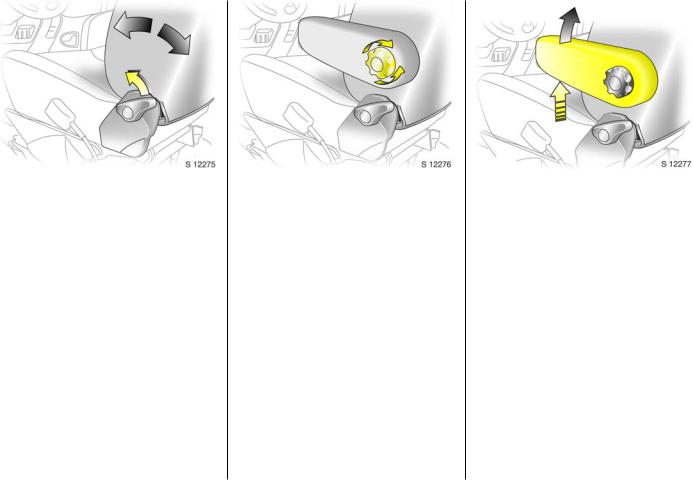
Adjusting the seat back: Pull release lever
Move seat b ack to suit seating position, it will lock in p osition when the lever is
released.
Adjusting the lumbar support 3: Turn handwheel
Ad just lumbar support to suit p ersonal requirements.
Do not lean on seat b ackrest whilst adjusting it.
Adjusting arm rest support 3:
Adjust arm rest support to suit personal requirements.
z Raise armrest in increments to desired height.
zTo reposition, fully ra ise armrest before low ering.

4 In brief
9Warning
Disregard of these instruc tions may lead
to injuries or endanger life. Vehicle passeng ers should be inform ed
accordingly.
6 Further information - see page 47.
Adjusting seat height 3: |
Adjusting head restraint height: |
Pull lever at side |
hold firmly and adjust height, |
Lift lever and remove weight from sea t to |
then release |
raise it or p ress d ow n on seat with body |
6 Head restraint position – see page 47, |
weight to low er it. |
further informa tion, rem oval – see page 48. |
Never adjust the driver’s seat whilst driving. |
|
It could m ove in a n uncontrolled m anner |
|
when the lever has been pulled . |
|
6 Seat position – see pag e 47. |
|
In brief |
5 |
Steering wheel adjustment: Adjust position
Adjust the steering w heel only when the vehic le is stationary.
Move the unlocking lever upw ards, adjust the w heel to the desired position, then
release the lever.
Push the lever firmly downwards to ensure that the w heel is locked in position.
6 Airbag systems - see page 61.
6 Seat belts – see p ages 57 to 59,
airbag systems 3 – see page 61, seat position – see pag e 47.
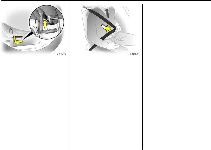
Fitting seat belt:
Draw seat belt smoothly from inertia reel, guide over shoulder
and engage in buckle
The belt must not b e twisted at any p oint. The lap b elt must lie snugly a gainst the
body. The back rest m ust not be tilted back too far (recommended tilting angle
approx. 25°).
To relea se belt, press red button on belt buckle.
6 In brief
Adjust interior 3 and exterior
mirrors:
Swivel to appropriate position
Move lever on underside of interior mirror housing to reduc e da zzle at night.
6 Further inform ation - see page 74.
Turn sw itch to right: switch operates righthand m irror.
Switc h in central position: mirror adjustment is off.
The low er aspherical mirrors are not adjustable.
Electrically adjustable exterior
mirrors 3:
Switch in door panel
Operational with the ignition on or off.
Turn switch to left: switch operates leftha nd mirror.
In brief |
7 |
|
|
|
|
Starter switch:
Diesel engine
St |
= |
Ignition off |
A |
= |
Steering unlocked , ignition off |
M |
= |
Ignition on: preheat (page 17) |
D |
= |
Start - (transmission in neutral) |
Petrol engine |
||
St |
= |
Ignition off |
A |
= |
Steering unlocked , ignition off |
M |
= |
Ignition on |
D |
= |
Start - (transmission in neutral) |
6 Elec tronic imm obiliz er - see pa ge 38.
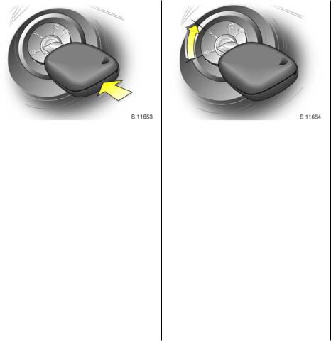
Releasing the steering column
lock:
To release the lock,
move steering wheel slightly and turn key to position ‘A’
6 Remove key a nd lock steering wheel - see page 18.

8 In brief

In brief |
9 |
|
Page |
|
1 |
Drink holder ....................................... |
55 |
2 |
Door window defroster vent............. |
83 |
3 |
Side ventila tion jets........................... |
83 |
4 |
Passeng er airbag 3.......................... |
61 |
5 |
Centre ventilation jets....................... |
82 |
6 |
Triple information display 3 ............ |
29 |
|
Graphic information display 3 ........ |
31 |
|
Colour inform ation d isplay 3........... |
31 |
7 |
Radio 3, Infotainm ent system 3 ..... |
35 |
8 |
Stalk for |
|
|
Parking lights, headlights flash, |
|
|
fog lights dipped and main b eam, |
12 |
|
turn signal lights................................ |
13 |
9 |
Driver’s airb ag .................................. |
61 |
|
Horn ................................................... |
13 |
10 |
Instruments........................................ |
20 |
11 |
Stalk for wind screen wiper |
|
|
and wa sh system ............................. |
14 |
|
Trip computer 3................................ |
26 |
12 |
Ashtray .............................................. |
55 |
|
|
Pa ge |
13 |
Fuse box .......................................... |
137 |
14 |
Coin tray |
|
15 |
Bonnet release lever ......................... |
46 |
16 |
Starter switch ...................................... |
7 |
17 |
Switches for |
|
|
headlight range adjustment ............ |
76 |
|
ESP |
|
|
(Electronic S tab ility Prog ra m) 3 .... |
106 |
|
Pa rk pilot 3 ..................................... |
107 |
18 |
Steering wheel adjustm ent lever ....... |
5 |
19 |
Radio/infotainm ent controls 3 ....... |
35 |
20 |
Cigarette lighter ............................... |
54 |
21 |
Switches for |
|
|
central locking 3............................... |
41 |
|
heated rear w indow 3...................... |
87 |
|
Tecshift 3 winter and laden |
|
|
prog ra mme ....................................... |
91 |
22 |
Hazard w arning switch .................... |
13 |
23 |
Heating a nd ventilation controls .... |
81 |
|
Rear a ir cond itioning 3 .................... |
86 |
24Utility hook
25Storage tra y
26Glove com partment
10 |
In brief |
|
|
|
|
|
|
|
|
|
|
|
|
|
|
|
|
Control indicators |
|
Y |
Fuel level: |
|
U |
Door open 3: |
||
|
|
|||||||
Ü |
Not used |
|
|
see pages 21, 100, 163. |
|
|
see pages 23. |
|
9 |
Hea dlight dipped b ea m: |
|
v |
ESP (Electronic Stability |
|
U |
Not used |
|
|
|
see p ages 12, 75. |
|
|
Program ) 3: |
|
Z |
Engine electronics, |
P |
|
|
see page 106. |
|
||||
Hea dlight main beam : |
|
D |
Engine electronics/Preheating |
|
|
Exhaust emissions: |
||
|
|
see p ages 12, 75. |
|
|
|
see page 23. |
||
|
|
|
|
system 3: |
|
|
||
r |
|
|
|
|
B |
Not used |
||
Fog tail lig ht: |
|
|
see page 17. |
|
||||
|
|
see p ages 12, 77. |
|
E |
Engine stop: |
|
F |
Engine oil life monitor 3: |
> |
Front fog lights 3: |
|
|
|||||
|
|
see page 21. |
|
|||||
|
|
|
|
see page 28. |
||||
|
|
see p ages 12, 77. |
|
p |
Alternator: |
|
|
|
u |
|
|
Tecshift 3 |
|||||
Anti-lock brake system 3: |
|
|
see page 22. |
|
||||
|
|
|
V |
Winter program me: |
||||
|
|
see p age 115. |
|
I |
Oil pressur e: |
|
||
8 |
Diesel par ticle filter 3: |
|
|
|
see page 91. |
|||
|
|
see page 22. |
|
|
||||
|
|
|
kg |
La den program me: |
||||
|
|
see p age 104. |
|
R |
Brake system: |
|
||
|
|
|
|
|
|
see page 92. |
||
F |
Not used |
|
|
see pages 22, 151. |
|
|
||
|
|
|
W |
Transmission electronics: |
||||
|
|
|
|
v |
Airb ag systems: |
|
||
C |
Stop engine: |
|
|
|
see page 94. |
|||
|
|
see page 61. |
|
|
||||
|
|
see p age 21. |
|
|
|
T |
Brake peda l app lication: |
|
|
|
|
H |
Front passenger |
|
|||
o |
Engine im mobiliser: |
|
|
|
see page 89. |
|||
|
|
see p ages 21, 38. |
|
|
air bag d eac tiva tion 3: |
|
A |
Automatic mod e: |
|
|
|
|
see page 65. |
|
|||
A Ser vice 3: |
|
X |
Driver’s seat b elt: |
|
|
see page 90. |
||
|
|
see p age 21. |
|
|
|
|
||
|
|
|
|
see page 57. |
|
|
|
|
O |
Turn sig na l lights: |
|
|
|
|
|
||
|
|
|
|
|
|
|||
|
|
see p ages 13, 76. |
|
|
|
|
|
|
|
|
|
|
|
|
|
|
|

In brief |
11 |
Lighting
7Lig ht switch:
see p ages 12, 75.
0Pa rking lights: see p ages 12, 75.
9Dipped beam : see p ages 12, 75.
PMain beam :
see p ages 12, 75.
>Front fog lights 3: see p ages 12, 77.
rFog tail lig ht: see p ages 12, 77.
OTurn sig na l lights: see p ages 13, 21.
¨Haza rd wa rning flashers: see p age 13, 76.
?Hea dlight range adjustm ent: see p age 76.
Heating and ventilation
xFan switc h: see page 82.
Air distribution: see page 81,
M to hea d area
L to hea d area and to foot area
K to foot area
J to hea d area and to demister
V to demister
ÜHeated rear windows a nd mirrors 3:
see pages 17, 87.
A.C Air conditioning system 3: see page 85.
4Air circulation: see page 85.
Windscreen wiper
Stalk positions: see page 14,
KTimed interval wipe or automatic wiping with rain sensor 3
1Slow
2Fast
n Windscreen wash
eTailgate w indow wiper 3
fTailgate w indow wash 3
Miscellaneous
jHorn:
see page 13.
/Bonnet:
see page 46.
) Ciga rette lighter: see page 54.
e/U Central locking 3: see page 41.
:Glove comp artm ent cooler 3: see page 86.
EPa rk p ilot 3: see page 107.

12 In brief
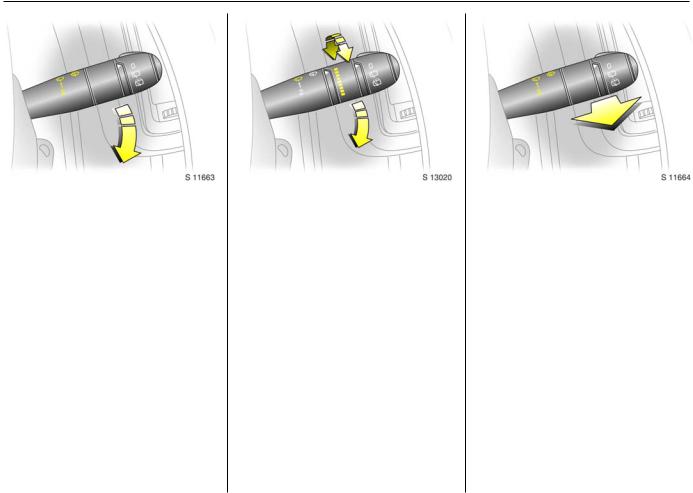
Light switch: |
Dipped and main beam : |
Fog lights: |
|||
7 |
= |
Off |
Headlight flash: |
7 |
= Off |
0 |
= |
Parking lights |
Pull stalk towards steering wheel |
> |
= On (front fog lights 3 only) |
9 P = Dipped or main beam |
To cha ng e the headlight beam, pull the |
>r = On (front fog lights 3 and |
|||
6 H eadlight wa rning device - see page 18, |
stalk tow ards the steering w heel, then |
|
fog tail light) |
||
further information - see pa ge 75, |
relea se when a click is felt. |
The fog lights will only illum ina te when the |
|||
Autom atic dipped beam a ctivation 3 |
Pulling the stalk towards the steering wheel |
ignition and head lig hts are sw itc hed on. |
|||
- see page 76, |
to the first stop operates the headlight |
|
|
||
head lig ht range adjustm ent - see page 76, |
|
|
|||
flash. |
|
|
|||
head lig hts when driving abroad |
|
|
|||
|
|
|
|||
- see page 78, |
|
|
|
||
daytim e running lights 3 - see page 75. |
|
|
|
||
|
|
|
|
|
|

In brief |
13 |
|
|
|
|
Turn signal lights: |
Hazard warning flashers: |
Horn: |
||||
stalk in rest position |
On |
= |
Press button ¨ |
Press any part of the steering wheel centre |
||
Upwards |
= |
Right turn |
Off |
= |
Press ¨ again |
to activate the horn. |
Downwards = |
Left turn |
When the hazard warning system is |
|
|||
When the steering wheel is turned back, the |
actuated, the button's control indicators |
|
||||
stalk automatically returns to its origina l |
flash in unison with the turn signal lights. |
|
||||
position. This will not hap pen when making a m inor steering manoeuvre such as la ne
changing.
When lane c hanging, move stalk part way
to first stop. When released, stalk will spring back.
For opera tion of the turn signal lig hts when towing - see pages 20 and 122.
14 In brief
Windscreen wiper: |
Automatic wiping with |
Windscreen wash system: |
|||||
Move stalk downwards |
rain sensor 3: |
|
Pull stalk towards steering wheel |
||||
K = |
Timed interval wipe |
Move stalk downwards |
Short pull |
||||
1 |
= |
Slow |
K = |
Automatic wiping with |
The wiper operates for one c ycle. |
||
2 |
= |
Fast |
|
|
rain sensor |
Long pull |
|
Return the stalk to its original position to |
1 |
= |
Slow |
|
Wash fluid is sprayed onto the windscreen, |
||
turn off. |
|
2 |
= |
Fast |
|
at the same tim e the wiper operates for |
|
|
|
|
The rain sensor d etects the amount of |
four cycles. |
|||
|
|
|
|
||||
|
|
|
water on the windscreen and a utoma tica lly |
Check regularly that the wind screen wash |
|||
|
|
|
regulates the wind screen wiper frequency . |
system is operating efficiently. |
|||
|
|
|
The sensitivity of the system can be |
On vehicles with rain sensor 3, keep the |
|||
|
|
|
adjusted by rotating the variable wipe: |
||||
|
|
|
sensor area clean. |
||||
|
|
|
Less sensitive |
= rotate down |
|||
|
|
|
6 Further inform ation - see page 153. |
||||
|
|
|
More sensitve |
= rotate up |
|||
|
|
|
|
||||
Upon starting the engine, autom atic wiping will need to be reselected.
6 Further information - see pages 153, 158.

In brief |
15 |
|
|
|
|
Back door and tailgate window
wash wipe system 3: Rotate switch
0 = Off
e= Wiper
f= Wash
Wash fluid is sprayed onto the window when the sta lk is moved to the second
position. The switch is spring loaded and will return to the ’wiper’ position when
released.
Check regula rly that the w indow wash system is operating efficiently.
6 Further inform ation - see page 153.
Manual transmission:
o |
= |
Neutral |
1 to 5/6= |
1st to 5th or 6th 3 gear |
|
R |
= |
Reverse gear |
When shifting up from 4th to 5th gear, pressure must be exerted towards the right
at the beginning of the shift operation.
When shifting from 5th to 4th gear, do not exert any force towards the left.
Reverse gear: with vehicle stationary,
declutch, pull up c ollar and move shift lever to the left a gainst resistance.
If the gear does not engage: with lever in neutra l, release clutch pedal and depress
again, then repea t gear selection.
Tecshift 3: |
|
|
N |
= |
Neutral |
o |
= |
Centre position |
-= Shift to lower gear
+ |
= |
Shift to higher gear |
A/M |
= |
Switch between |
|
|
automatic or manual |
|
|
mode |
R |
= |
Reverse |
The selector lever m ust be moved in the
app ropriate direc tion as far a s it w ill go. Upon release, it automatically returns to
the centre position. Pay heed to the gear / mode indicator in the transm ission
display.
6 Further inform ation - see page 89.
16 In brief
Before driving check:
z Tyre pressures and c ondition.
zEngine oil level and fluid levels in engine com partment (see pag es 145 to 148).
zAll windows, mirrors, exterior lighting
and num ber p la tes free from dirt, snow and ice and operational.
zObjects are securely located a nd will not be thrown forward in the event of sudden braking.
zSeats, seat belts and mirrors correctly adjusted .
z Bra ke op eration. |
Exhaust gases are poisonous |
Starting, petrol engine: |
|
Exhaust gases contain carbon monoxide, |
Transmission in neutral |
|
whic h is extrem ely poisonous b ut has no |
Depress clutch |
|
od our or colour. |
Do not accelerate |
|
Therefore, never inhale exhaust gases, and |
Turn key to D |
|
never run the engine in an enclosed space. |
The increased engine speed a utomatica lly |
|
You should also avoid driving with the |
returns to norm al idling speed as the |
|
eng ine tem perature rises. |
|
|
doors open, as exhaust gases c ould enter |
|
|
|
|
|
the passenger compartment. |
6 Electronic im mobilizer - see p age 38, |
|
6 Exhaust ga s - see p age 105. |
further inform ation - see p ages 96, 97, 99. |
|
|

In brief |
17 |
|
|
|
|
Starting, diesel engine:
Transmission in neutral Depress clutch
Do not accelerate Turn key to M
When preheating control indicator goes out 1 ),
turn key to D
6 Electronic imm ob iliz er - see pag e 38, further information - see pa ges 96, 97, 99.
1)Preh eating system sw itch es on o nly if o utside temperature is low .
Drying misted-up or iced-up
windows:
Set the temperature switch to red
and fan to position 4, set air distribution to V
Close centre ventila tion jets; op en side
ventilation jets and direct them tow ards the door windows.
6 Heating, ventila tion - see pa ge 81, air conditioning system - see page 85.
Heated rear windows 3, heated exterior mirrors 3
Press Ü |
= |
On |
Press Ü again= |
Off |
|
6 Further information - see page 87.
18 |
In brief |
|
|
|
|
|
|
|
|
|
|
|
Warning buzzers |
|
|
|
|
|
|
|
|
|
While driving: |
|
|
|
|
z Operating the ind icators. |
|
|
|
|
z Illumination of low fuel control ind ic ator. |
|
|
|
|
z Tec shift 3, high c lutch tempera ture. |
|
|
|
|
z Seat belt not fastened 3. |
|
|
|
|
When the vehicle is parked and driver’s |
|
|
|
|
door is opened: |
|
|
|
|
z Headlights switched on. |
|
|
|
|
z Tec shift 3: neutra l not selected, foot |
|
|
|
|
brake not depressed or handbrake not |
|
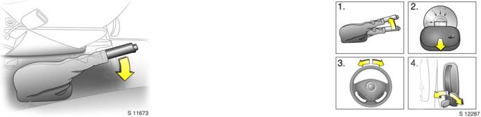
Releasing the hand brake: |
applied. |
Parking the vehicle: |
||
Raise lever slightly, |
6 Driving hints - see p age 95, |
Apply hand brake firmly |
||
press lock button, |
Save fuel, protect the environment - see |
Close windows |
||
lower lever fully |
page 97. |
Switch off engine |
||
Drive carefully, economically and with the |
|
Remove key |
||
environment in m ind. While driving , do not |
|
Engage steering wheel lock |
||
do anything that could distract you. |
|
Lock doors |
||
|
|
|
|
6 Further inform ation - see pages 38, 96, |
|
|
|
|
remote control - see page 39, |
|
|
|
|
central loc king system - see pa ge 41, |
|
|
|
|
Vauxhall alarm system - see page 43. |
|
|
|
|
|

In brief |
19 |
Advice when parking:
zAlwa ys app ly hand brake firm ly . Engage first gear or reverse gear. On slopes apply the hand brak e as far as it w ill go.
zTurn steering wheel until lock is felt to engage (anti-theft protection).
zSwitch off exterior lights, otherw ise the
headlight warning device will sound when the d river’s door is opened.
zCooling fans may run on after the engine has been switched off.
zDo not p ark vehic le on easily ignita ble surfaces as the hot exha ust system could cause the surfa ce to ignite.
Service work, maintenance
We recomm end tha t you entrust all w ork to
your Vauxhall Authorised R epairer, who can provide you w ith reliable service and
correctly perform all work according to factory instructions.
Vauxhall Service - see page 142.
Genuine Vauxhall Parts and Accessories
We recommend “Genuine Vauxhall Parts and Accessories” and c onversion parts
released expressly for your vehicle type.
These parts have undergone special tests
to establish their reliability, safety and specific suitability for your vehicle. Despite
continuous ma rket m onitoring, we cannot assess or guarantee these a ttributes for
other products, even if they have been granted ap proval by the relevant
authorities or in some other form .
"Genuine Vauxhall Parts and Accessories"
and conversion parts approved by Vauxhall c an be ob tained from your
Vauxhall Authorised Repairer, w ho c an give advice about permitted technic al
cha ng es and correc t installation.
9Warning
Carry out regularly the check s
rec om mended in this Owner's Manual.
Ensure that your vehicle is serviced at the
service intervals spec ified in the Servic e Booklet. We recommend that you entrust
this work to your Vauxhall Authorised Repairer.
Have faults remedied without d elay! Consult a w orkshop. We recommend your
Vauxhall Authorised R epairer. If necessary, interrupt your journey.
6 Maintenance - see pages 144 to 155.
That was a brief overview of the most important information for
your first drive in your Vivaro.
Your vehicle has still more
instrum ents and controls, possibly also optional
equipment.
The remaining chapters of the
Owner’s Manual contain important information on
operation, safety and maintenance as well as a
com plete index.

20 In struments
Instruments
Control indicators ............................... |
20 |
Fuel gauge .......................................... |
23 |
Coolant temperature gauge.............. |
24 |
Transm ission display 3 ...................... |
24 |
Tachometer......................................... |
25 |
Speed om eter....................................... |
25 |
Electronic odometer/clock 3.............. |
25 |
Trip computer 3 ................................. |
26 |
Engine oil life monitor for vehicles |
|
with diesel particle filter 3............... |
28 |
Triple information display 3 .............. |
29 |
Graphical information displa y 3 or |
|
colour information disp la y 3, |
|
selecting functions ........................... |
31 |
Radio 3................................................ |
35 |
Control indicators
The control indica tors described here are
not p resent in all vehicles. The description applies to all instrum ent versions.
Ü
Not used
9
Hea dlight dipped bea m
Lights up when d ipped beam is on.
P
Hea dlight main b eam
Lights up when m ain beam is on and when headlight flash is operated.
r
Fog tail light
Lights up when the fog tail light is switched on.
>
Front fog lights 3
Lights up when front fog lig hts are switched on.
u
Anti -lock b rake system see page 115.
8
Diesel particle filter 3
Lights up when reg eneration of diesel particle filter is required - see pa ge 104.
F
Not used

Instruments 21
v
ESP (Electronic Stability Pr og ram) 3 see page 106.
F
Eng ine oil life monitor 3
See page 28.
kg
Tecshift Laden progra mme 3
Control indicator illum inates in
transm ission display when Laden programme is enab led - see p age 92.
T
Tecshift foot bra ke app lication 3 see page 89.
W
Tecshift elec tronics 3
Lights up b riefly when ignition is switched
on. Illuminates in transmission disp la y when fault has occurred - see page 94.
A
Tecshift autom atic m ode 3
Control indicator illum inates in
transm ission display when a utomatic mode is selected - see pa ge 90.
V
Tecshift Winter progra mme 3
Control indicator illum inates in
transm ission display when Winter programme is enab led - see p age 91.
O
Turn sig nal lig hts
Flashes when turn signa l lights are on.
Flashes rapidly: a turn sig nal bulb has fa iled.
An audible warning can be heard when the turn signal lights are on. When towing a
caravan or trailer, the pitch of the audible warning chang es.
C
Stop engine
If C lights up in conjunction with p, I,
E or R, stop eng ine immediately and consult a workshop. We recommend your
Vauxhall Authorised Repairer.
o
Engine im mobilizer
If the indicator flashes when the ignition is on, there is a fault in the immobilizer
system; the engine cannot be started - see page 38.
A
Service / engine electronics 3
If A lights up in conjunction with u or v,
interrupt your journey. Consult a workshop. We rec om mend your Vauxhall Authorised
Repairer.
D
Prehea ting/Fuel filter/Engine elec tronics
Lights up b riefly during engine preheating . If illuminated constantly it indica tes:
zThe presence of wa ter in the diesel fuel filter 3. Drain fuel filter of resid ua l water, see page 149.
zAn electronic system failure, consult a
workshop. We rec om mend your Vauxhall Authorised Repairer.
Y
Fuel level
If it lights up: fuel level low, fill up. N ever let the tank become em pty!
With diesel engines it is not possible to start the engine after the tank has b een run
empty. The fuel system must be bled first.
22 |
In struments |
|
|
|
|
|
|
|
|
|
|
|
|
|
|
|
|
|
|
E |
|
|
I |
|
|
R |
|
||
|
|
|
|||||||
Eng ine stop |
|
Oil p ressure |
|
|
Brake system |
|
|||
Will light up in conjunction with C engine |
|
Lights up when ignition is switched on. |
|
|
Lights up when ignition is switched on if |
|
|||
if coolant temp erature is too high. Stop |
|
Goes out after a short period of tim e. Can |
|
|
hand brake is ap plied and/or fluid level for |
|
|||
vehic le - c onsult a workshop . We |
|
lig ht up intermittently when id ling with hot |
|
|
brak e hyd ra ulics is too low. |
|
|||
recom mend your Vauxhall Authorised |
|
engine; must g o out when engine sp eed is |
|
|
|
|
|||
|
|
|
9Warning |
|
|||||
Repairer. |
|
increased. |
|
|
|
||||
p |
|
|
If illum inated during driving: |
|
|
|
|
||
|
|
|
|
If it lights up when the ha nd brake is not |
|
||||
Alternator |
|
Engine lubrication may be interrupted, |
|
|
|
||||
|
|
|
applied : stop vehicle; interrupt your |
|
|||||
Lights up w hen ignition is switched on. |
|
resulting in da mage to the engine and/or |
|
|
|
||||
|
|
|
journey immediately . Consult a |
|
|||||
Goes out after engine is started. |
|
lock ing of the driving w heels: |
|
|
|
||||
|
|
|
workshop. We recom mend your Vauxhall |
|
|||||
If illuminated during driving: |
|
z Depress clutch. |
|
|
|
||||
|
|
|
Authorised Repairer. |
|
|||||
Stop vehicle and switch off engine. The |
|
z Move gear shift lever to neutra l. |
|
|
|
|
|||
battery is not being charged and the |
|
z Sw itch off ignition (to position A). |
|
|
6 Further information - see page 113. |
|
|||
engine cooling may be interrupted. The |
|
Considerably greater force will be |
|
|
|
||||
brake servo unit may c ease to be effective. |
|
req uired for braking a nd steering. |
|
|
v |
|
|||
Interrupt your journey, c onsult a workshop . |
|
|
|
|
|
|
|||
We recommend your Vauxhall Authorised |
|
9Warning |
|
|
|
Airb ag 3 |
|
||
Repairer. |
|
|
|
|
|
see page 61. |
|
||
|
|
|
|
Do not rem ove key until vehicle has come |
|
|
|
H |
|
|
|
|
|
to a standstill, otherwise the steering |
|
|
|
|
|
|
|
|
|
column loc k could eng age unexpectedly. |
|
|
|
Front passenger airba g deactivation 3 |
|
|
|
|
|
|
|
|
|
Lights up when the ig nition is switched on |
|
|
|
|
|
Consult a work shop. We recom mend your |
|
|
and remains illum inated when the front |
|
|
|
|
|
|
|
|
passenger airbag has been deactivated. |
|
||
|
|
|
|
Vauxhall Authorised Repairer. |
|
|
|
||
|
|
|
|
|
|
If Hilluminated in conjunction w ith v or A |
|
||
|
|
|
|
|
|
|
|
|
|
|
|
|
|
|
|
|
|
consult a workshop. We recommend your |
|
|
|
|
|
|
|
|
|
Vauxhall Authorised Repairer. |
|
|
|
|
|
|
|
|
|
6 Further information - see page 65. |
|
|
|
|
|
|
|
|
|
|
|

Instruments 23
X
Driver’s seat b elt
Lights up when ignition is switched on a nd if driver’s seat belt is not engaged.
Seat belts, see page 57.
U
Door open 3
Operational only when ignition is switched
on. Lig hts up when driver’s, passeng er’s or side loading doors are open.
U
Not used.
Z
Exhaust em issions 3
Control indica tor lights up when ignition is
switched on. Goes out shortly after eng ine starts.
If it lights up when the engine is running: Fault in emission control system . The
permitted em ission limits m ay b e exc eeded. Consult a workshop. We
recommend your Vauxhall Authorised Repairer.
If it flashes when the engine is running: For fa ult that ca n lea d to destruction of the
catalytic converter, see pa ge 102. Consult a workshop immediately. We recommend
that you consult your Va uxhall Authorised Repairer.
B
Not used
Fuel gauge
Display of fuel level:
Illumination of bars disp la ys fuel level.
When gauge indicates fuel supply low, fuel
warning Y illumina tes = fill up. See page 99.
N ever let ta nk bec om e empty!

24 In struments
For physical reasons, the coola nt
temperature gauge show s the coolant temperature only if the coolant level is
adeq uate.
Coolant tem perature gauge
Display of coolant tem perature:
Bars illum inated |
= |
Eng ine opera ting |
in lower area |
|
tempera ture not yet |
|
|
reached |
Bars illum inated |
= |
N orm al operating |
up to centra l |
|
tempera ture |
area |
|
|
Bars illum inated |
= |
Temperature too |
into uppermost |
|
high. Stop vehicle, |
zone |
|
switch off engine. |
or indicator E |
|
Danger to engine. |
illuminates 3 |
|
Check c oolant level |
|
|
imm ediately. See |
|
|
pag e 150. |
Transmission display 3
Display of the selected g ear and mode w ith Tecshift 3.
N N eutral or idling position. R Reverse gear.
A Automatic mode. kg Laden prog ra mme.
VWinter programm e.
TFoot brake application.
WTransm ission electronics.

Instruments 25
Tachometer
Making use of the tachometer helps to
save fuel; it indicates the engine speed in revolutions per m inute.
Warning zone on right: ma ximum permissible engine speed exc eeded,
danger to engine.
If possib le, d rive in each gear in the low
engine sp eed range (between app rox . 2000 a nd 3000 rpm) and m ainta in an even
vehic le speed.
Speedometer
Indicates the vehicle speed .
Certain vehicle variants feature a speed regulator 3 1 ) which restricts the vehicle
maximum speed . As a visible indica tion of this, a warning label is located on the
instrument panel.
1)Depending on driving environm ent (e.g. when
descen ding steep in clines) the vehicle speed can exceed set lim its. In su ch ins tances it
remains the driver’s respo nsibility to adhere to the specific speed lim its.
Electronic odom eter/clock 3
Norm al m ode:
The od om eter and clock a re visible.
Reset:
The reset button is loc ated alongside the speedometer. Press b uttton once to display
the trip odometer.
Press the button and hold, the display will
flash and after 1 second will reset to z ero. Press the button again to return the
odometer to normal m ode.
Clock a djust mod e:
With the d isplay in normal mode press and hold the button, a nd the minutes reading
will begin to increase.
After the button is released the clock will
continue to fla sh for a further 5 seconds to ena ble further ad justments to be made.
 Loading...