


Edition: September 2010
Revision: November 2011
Publication No. SM1E-1Z51U2
All Rights Reserved. No part of this Service Manual may be reproduced or stored in a retrieval system, or transmitted in any form, or by any means, electronic, mechanical, recording or otherwise, without the prior written permission of NISSAN MOTOR CO., LTD.
QUICK REFERENCE INDEX
A |
GENERAL INFORMATION |
GI |
General Information |
B |
ENGINE |
EM |
Engine Mechanical |
|
|
LU |
Engine Lubrication System |
|
|
CO |
Engine Cooling System |
|
|
EC |
Engine Control System |
|
|
FL |
Fuel System |
|
|
EX |
Exhaust System |
|
|
STR |
Starting System |
|
|
ACC |
Accelerator Control System |
C |
ELECTRIC POWER TRAIN |
HBC |
Hybrid Control System |
|
|
HBB |
Hybrid Battery System |
|
|
HBR |
Hybrid Brake System |
|
|
EVC |
EV Control System |
|
|
TMS |
Traction Motor System |
|
|
EVB |
EV Battery System |
|
|
VC |
Vehicle Charging System |
|
|
HCO |
High Voltage Cooling System |
D |
TRANSMISSION & DRIVELINE |
CL |
Clutch |
|
|
TM |
Transaxle & Transmission |
|
|
DLN |
Driveline |
|
|
FAX |
Front Axle |
|
|
RAX |
Rear Axle |
E |
SUSPENSION |
FSU |
Front Suspension |
|
|
RSU |
Rear Suspension |
|
|
SCS |
Suspension Control System |
|
|
WT |
Road Wheels & Tires |
F |
BRAKES |
BR |
Brake System |
|
|
PB |
Parking Brake System |
|
|
BRC |
Brake Control System |
G |
STEERING |
ST |
Steering System |
|
|
STC |
Steering Control System |
H |
RESTRAINTS |
SB |
Seat Belt |
|
|
SBC |
Seat Belt Control System |
|
|
SR |
SRS Airbag |
|
|
SRC |
SRS Airbag Control System |
I VENTILATION, HEATER & AIR |
VTL |
Ventilation System |
|
|
CONDITIONER |
HA |
Heater & Air Conditioning System |
|
|
HAC |
Heater & Air Conditioning Control System |
J |
BODY INTERIOR |
INT |
Interior |
|
|
IP |
Instrument Panel |
|
|
SE |
Seat |
|
|
ADP |
Automatic Drive Positioner |
K |
BODY EXTERIOR, DOORS, |
DLK |
Door & Lock |
|
ROOF & VEHICLE SECURITY |
SEC |
Security Control System |
|
|
GW |
Glass & Window System |
|
|
PWC |
Power Window Control System |
|
|
RF |
Roof |
|
|
HD |
Hood |
|
|
EXT |
Exterior |
|
|
BRM |
Body Repair |
L |
DRIVER CONTROLS |
MIR |
Mirrors |
|
|
EXL |
Exterior Lighting System |
|
|
INL |
Interior Lighting System |
|
|
WW |
Wiper & Washer |
|
|
DEF |
Defogger |
|
|
HRN |
Horn |
|
|
VSP |
Approaching Vehicle Sound for Pedestrians (VSP) |
M ELECTRICAL & POWER CON- |
PWO |
Power Outlet |
|
|
TROL |
BCS |
Body Control System |
|
|
LAN |
LAN System |
|
|
PCS |
Power Control System |
|
|
CHG |
Charging System |
|
|
PG |
Power Supply, Ground & Circuit Elements |
N |
DRIVER INFORMATION & |
MWI |
Meter, Warning Lamp & Indicator |
|
MULTIMEDIA |
WCS |
Warning Chime System |
|
|
SN |
Sonar System |
|
|
AV |
Audio, Visual & Navigation System |
O |
CRUISE CONTROL & |
CCS |
Cruise Control System |
|
DRIVER ASSISTANCE |
DAS |
Driver Assistance System |
|
|
DMS |
Drive Mode System |
P |
MAINTENANCE |
MA |
Maintenance |
A B C D E F G H I J K L M N O P

FOREWORD
This manual contains maintenance and repair procedure for the 2011 NISSAN MURANO.
In order to assure your safety and the efficient functioning of the vehicle, this manual should be read thoroughly. It is especially important that the PRECAUTIONS in the GI section be completely understood before starting any repair task.
All information in this manual is based on the latest product information at the time of publication. The right is reserved to make changes in specifications and methods at any time without notice.
IMPORTANT SAFETY NOTICE
The proper performance of service is essential for both the safety of the technician and the efficient functioning of the vehicle.
The service methods in this Service Manual are described in such a manner that the service may be performed safely and accurately. Service varies with the procedures used, the skills of the technician and the tools and parts available. Accordingly, anyone using service procedures, tools or parts which are not specifically recommended by NISSAN must first be completely satisfied that neither personal
safety nor the vehicle’s safety will be jeopardized by the service method selected.
PLEASE HELP MAKE THIS SERVICE MANUAL BETTER!
Your comments are important to NISSAN and will help us to improve our Service Manuals. Use this form to report any issues or comments you may have regarding our Service Manuals. Please print this form and type or write your comments below. Mail or fax to:
Nissan North America, Inc. Technical Service Information 39001 Sunrise Drive, P.O. Box 9200 Farmington Hills, MI USA 48331 FAX: (248) 488-3880
SERVICE MANUAL: Model: Year:
PUBLICATION NO. (Refer to Quick Reference Index ):
Please describe any Service Manual issues or problems in detail:
Page number(s) Note: Please include a copy of each page, marked with your comments.
Are the trouble diagnosis procedures logical and easy to use? (circle your answer) |
YES |
NO |
If no, what page number(s)? Note: Please include a copy of each page, marked with your comments.
Please describe the issue or problem in detail:
Is the organization of the manual clear and easy to follow? (circle your answer) |
YES |
NO |
Please comment:
What information should be included in NISSAN Service Manuals to better support you in servicing or repairing customer vehicles?
DATE: |
|
|
YOUR NAME: |
|
|
|
|
|
|
POSITION: |
|
|
|||
DEALER: |
|
|
|
DEALER NO.: |
|
|
ADDRESS: |
|
|
||||||
CITY: |
|
|
STATE/PROV./COUNTRY: |
|
|
ZIP/POSTAL CODE: |
|
||||||||

QUICK REFERENCE CHART MURANO |
2011 |
QUICK REFERENCE CHART MURANO ENGINE TUNE-UP DATA (VQ35DE)
PFP:00000
ELS0003W
Engine model |
|
|
|
VQ35DE |
|
|
|
|
|
|
|
Firing order |
|
|
|
1-2-3-4-5-6 |
|
|
|
|
|
|
|
Idle speed |
|
|
rpm |
600 ± 50 |
|
CVT (In “P” or “N” position) |
|
|
|
||
|
|
|
|
||
|
|
|
|
|
|
Ignition timing (BTDC at idle speed) |
|
|
12° ± 5° |
||
CVT (In “P” or “N” position) |
|
|
|
||
|
|
|
|
||
|
|
|
|
|
|
Tensions of drive belt |
|
|
|
Auto adjustment by auto tensioner |
|
|
|
|
|
|
|
Radiator cap relief pressure |
kPa (kg/cm2 , psi) |
|
|
||
|
|
Standard |
|
|
122.3 - 151.7 (1.2 - 1.5, 17.7 - 22.0) |
|
|
|
|
|
|
|
|
Limit |
|
|
108 (1.1, 15.6) |
|
|
|
|
||
Cooling system leakage testing pres- |
kPa (kg/cm2 , psi) |
|
156 (1.6, 22.6) |
||
sure |
|
|
|||
|
|
|
|
||
|
|
|
|
||
Compression pressure |
|
kPa (kg/cm2 , psi)/rpm |
|
||
|
|
Standard |
|
|
1,275 (13.0, 185)/300 |
|
|
|
|
|
|
|
|
Minimum |
|
|
981 (10.0, 142)/300 |
|
|
|
|
|
|
Spark plug |
Make |
|
|
DENSO |
|
|
|
|
|
|
|
|
|
Standard type |
|
|
FXE22HR11 |
|
|
|
|
|
|
|
|
Gap |
Standard |
|
1.1 mm (0.043 in) |
|
|
|
|
|
|
|
|
Limit |
|
1.4 mm (0.055 in) |
|
|
|
|
|
||
|
|
|
|
|
|
|
QUICK REFERENCE CHART MURANO |
2011 |
|||||
FRONT WHEEL ALIGNMENT |
|
|
|
|
ELS0003X |
||
FOR USA AND MEXICO MODELS |
|
|
|
|
|
|
|
|
Item |
|
|
Standard |
|||
|
|
|
|
|
|
|
|
Measurement wheel |
|
|
Left side |
|
Right side |
||
|
|
|
|
|
|
|
|
|
|
Minimum |
|
–1° 00′ (–1.00°) |
|
–1° 15′ (–1.25°) |
|
|
|
|
|
|
|
|
|
Camber |
Nominal |
|
–0° 15′ (–0.25°) |
|
–0° 30′ (–0.50°) |
||
|
|
|
|
|
|
||
Degree minute (Decimal degree) |
Maximum |
|
0° 30′ (0.50°) |
|
0° 15′ (0.25°) |
||
|
|
|
|
|
|
|
|
|
|
Left and right difference*1 |
|
–0° 18′ (–0° 30′) - 0° 48′ (0.80°) |
|
||
|
|
Minimum |
|
3° 55′ (3.92°) |
|
4° 15′ (4.25°) |
|
|
|
|
|
|
|
|
|
Caster |
Nominal |
|
4° 40′ (4.67°) |
|
5° 00′ (5.00°) |
||
|
|
|
|
|
|
||
Degree minute (Decimal degree) |
Maximum |
|
5° 25′ (5.41°) |
|
5° 45′ (5.75°) |
||
|
|
|
|
|
|
|
|
|
|
Left and right difference*1 |
|
–0° 18′ (–0° 30′) - 0° 48′ (0.80°) |
|
||
Kingpin inclination |
Minimum |
|
12° 00′ (12.00°) |
||||
|
|
|
|
|
|
||
Nominal |
|
12° 45′ (12.75°) |
|||||
Degree minute (Decimal degree) |
|
||||||
|
|
|
|
|
|
||
Maximum |
|
13° 30′ (13.50°) |
|||||
|
|
|
|||||
|
|
|
|
|
|
|
|
|
Total toe-in |
Minimum |
|
In 0.5 mm (0.020 in) |
|||
|
|
|
|
|
|
|
|
|
Nominal |
|
In 1.5 mm (0.059 in) |
||||
|
Distance |
|
|||||
|
|
|
|
|
|
|
|
Toe-in |
Maximum |
|
In 2.5 mm (0.098 in) |
||||
|
|
||||||
|
|
|
|
|
|
|
|
Toe angle (left wheel or right wheel) |
Minimum |
|
In 0° 01′ (0.02°) |
||||
|
|
||||||
|
|
|
|
|
|
|
|
|
Nominal |
|
In 0° 03′ (0.05°) |
||||
|
Degree minute (Decimal degree) |
|
|||||
|
|
|
|
|
|
|
|
|
Maximum |
|
In 0° 05′ (0.08°) |
||||
|
|
|
|||||
|
|
|
|
|
|
|
|
Measure value under unladen*2 conditions. |
|
|
|
|
|
|
|
*1: A difference when I assumed the right side a standard (right side – left side = difference). |
|
|
|
|
|||
*2: Fuel, engine coolant and lubricant are oil full. Spare tire, jack, hand tools and mats are in designated positions. |
|
|
|||||
FOR CANADA MODELS |
|
|
|
|
|
|
|
|
|
|
|
|
|
|
|
|
Item |
|
|
Standard |
|||
|
|
|
|
|
|
||
Measurement wheel |
|
|
Left side |
|
Right side |
||
|
|
|
|
|
|
|
|
|
|
Minimum |
|
–1° 00′ (–1.00°) |
|
–1° 15′ (–1.25°) |
|
|
|
|
|
|
|
|
|
Camber |
Nominal |
|
–0° 15′ (–0.25°) |
|
–0° 30′ (–0.50°) |
||
|
|
|
|
|
|
||
Degree minute (Decimal degree) |
Maximum |
|
0° 30′ (0.50°) |
|
0° 15′ (0.25°) |
||
|
|
|
|
|
|
|
|
|
|
Left and right difference*1 |
|
–0° 18′ (–0° 30′) - 0° 48′ (0.80°) |
|
||
|
|
Minimum |
|
3° 55′ (3.92°) |
|
4° 10′ (4.17°) |
|
|
|
|
|
|
|
|
|
Caster |
Nominal |
|
4° 40′ (4.67°) |
|
4° 55′ (4.92°) |
||
|
|
|
|
|
|
||
Degree minute (Decimal degree) |
Maximum |
|
5° 25′ (5.41°) |
|
5° 40′ (5.66°) |
||
|
|
|
|
|
|
|
|
|
|
Left and right difference*1 |
|
–0° 18′ (–0° 30′) - 0° 48′ (0.80°) |
|
||
Kingpin inclination |
Minimum |
|
11° 55′ (11.92°) |
||||
|
|
|
|
|
|
||
Nominal |
|
12° 40′ (12.67°) |
|||||
Degree minute (Decimal degree) |
|
||||||
|
|
|
|
|
|
||
Maximum |
|
13° 25′ (13.41°) |
|||||
|
|
|
|||||
|
|
|
|
|
|
|
|
|
Total toe-in |
Minimum |
|
In 0.5 mm (0.020 in) |
|||
|
|
|
|
|
|
|
|
|
Nominal |
|
In 1.5 mm (0.059 in) |
||||
|
Distance |
|
|||||
|
|
|
|
|
|
|
|
Toe-in |
Maximum |
|
In 2.5 mm (0.098 in) |
||||
|
|
||||||
|
|
|
|
|
|
|
|
Toe angle (left wheel or right wheel) |
Minimum |
|
In 0° 01′ (0.02°) |
||||
|
|
||||||
|
|
|
|
|
|
|
|
|
Nominal |
|
In 0° 03′ (0.05°) |
||||
|
Degree minute (Decimal degree) |
|
|||||
|
|
|
|
|
|
|
|
|
Maximum |
|
In 0° 05′ (0.08°) |
||||
|
|
|
|||||
|
|
|
|
|
|
|
|
Measure value under unladen*2 conditions.
*1: A difference when I assumed the right side a standard (right side – left side = difference).
*2: Fuel, engine coolant and lubricant are oil full. Spare tire, jack, hand tools and mats are in designated positions.
|
QUICK REFERENCE CHART MURANO |
2011 |
|||
REAR WHEEL ALIGNMENT |
|
|
ELS0003Y |
||
FOR USA AND MEXICO MODELS |
|
|
|
|
|
|
Item |
|
|
Standard |
|
|
|
|
|
|
|
Camber |
Minimum |
|
–1° 13′ (–1.21°) |
||
|
|
|
|
||
Nominal |
|
–0° 43′ (–0.72°) |
|||
Degree minute (Decimal degree) |
|
||||
|
|
|
|
||
|
|
Maximum |
|
–0° 13′ (–0.21°) |
|
|
|
|
|
|
|
|
Total toe-in |
Minimum |
|
In 0.9 mm (0.035 in) |
|
|
|
|
|
|
|
|
Nominal |
|
In 2.7 mm (0.106 in) |
||
|
Distance |
|
|||
|
|
|
|
|
|
Toe-in |
|
Maximum |
|
In 4.5 mm (0.177 in) |
|
|
|
|
|
|
|
Toe angle (left wheel or right wheel) |
Minimum |
|
In 0° 02′ (0.04°) |
||
|
|
||||
|
|
|
|
|
|
|
Nominal |
|
In 0° 06′ (0.10°) |
||
|
Degree minute (Decimal degree) |
|
|||
|
|
|
|
|
|
|
|
Maximum |
|
In 0° 10′ (0.16°) |
|
|
|
|
|
|
|
Measure value under unladen* conditions.
* : Fuel, engine coolant and lubricant are full. Spare tire, jack, hand tools and mats are in designated positions.
FOR CANADA MODELS
|
Item |
|
Standard |
|
|
|
|
|
|
Camber |
Minimum |
–1° 11′ (–1.18°) |
||
|
|
|||
Nominal |
–0° 41′ (–0.68°) |
|||
Degree minute (Decimal degree) |
||||
|
|
|||
|
|
Maximum |
–0° 11′ (–0.18°) |
|
|
|
|
|
|
|
Total toe-in |
Minimum |
In 0.9 mm (0.035 in) |
|
|
|
|
||
|
Nominal |
In 2.7 mm (0.106 in) |
||
|
Distance |
|||
|
|
|
||
Toe-in |
|
Maximum |
In 4.5 mm (0.177 in) |
|
|
|
|
||
Toe angle (left wheel or right wheel) |
Minimum |
In 0° 02′ (0.04°) |
||
|
||||
|
|
|
||
|
Nominal |
In 0° 06′ (0.10°) |
||
|
Degree minute (Decimal degree) |
|||
|
|
|
||
|
|
Maximum |
In 0° 10′ (0.16°) |
|
|
|
|
|
|
Measure value under unladen* conditions.
* : Fuel, engine coolant and lubricant are full. Spare tire, jack, hand tools and mats are in designated positions.
|
|
|
QUICK REFERENCE CHART MURANO |
2011 |
|||||||
BRAKE PEDAL |
|
|
|
|
|
ELS0003Z |
|||||
|
|
|
|
|
|
|
|
|
|
Unit: mm (in) |
|
|
|
|
|
|
|
|
|
|
|
|
|
|
|
Item |
|
|
|
Standard |
|
|
|||
|
|
|
|
|
|
|
|
|
|
||
Brake pedal height |
197.1 - 207.1 (7.76 - 8.15) |
|
|||||||||
|
|
|
|
|
|
|
|
|
|
|
|
Clearance between the stop lamp switch and ASCD brake switch |
0.20 - 1.96 (0.0079 - 0.0772) |
|
|||||||||
threaded end and the stopper rubber |
|
||||||||||
|
|
|
|
|
|
|
|||||
|
|
|
|
|
|
|
|
|
|
|
|
Brake pedal play |
|
|
|
3.0 - 11.0 (0.118 - 0.433) |
|
||||||
|
|
|
|
|
|
|
|
|
|
|
|
Depressed brake pedal height |
|
|
|
128 (5.04) or more |
|
|
|||||
[Depressing 490 N (50 kg, 110 lb) while turning the engine ON] |
|
|
|
|
|
||||||
|
|
|
|
|
|
|
|||||
|
|
|
|
|
|
|
|
|
|
|
|
BRAKE BOOSTER |
|
|
|
|
|
|
|
||||
Vacuum type |
|
|
|
|
|
|
|
|
|
|
|
|
|
|
|
|
|
|
|
|
|
Unit: mm (in) |
|
|
|
|
|
|
|
|
|
|
|
|
|
|
|
Item |
|
|
|
Standard |
|
|
|||
|
|
|
|
|
|
|
|
|
|
|
|
Input rod length |
|
|
|
127 (5.00) |
|
|
|||||
|
|
|
|
|
|
|
|
|
|
|
|
FRONT DISC BRAKE |
|
|
|
|
|
Unit: mm (in) |
|||||
|
|
|
|
|
|
|
|
|
|
||
|
|
|
|
|
|
|
|
|
|
|
|
|
|
Item |
|
|
|
Limit |
|
|
|||
|
|
|
|
|
|
|
|
|
|
|
|
Brake pad |
|
Wear thickness |
2.0 (0.079) |
|
|
||||||
|
|
|
|
|
|
|
|
|
|
|
|
|
|
Wear thickness |
26.0 (1.024) |
|
|
||||||
|
|
|
|
|
|
|
|
|
|
|
|
Disc rotor |
|
Thickness variation (measured at 8 positions) |
0.008 (0.0003) |
|
|
||||||
|
|
|
|
|
|
|
|
|
|
|
|
|
|
Runout (with it attached to the vehicle) |
|
|
|
0.040 (0.0016) or less |
|
|
|||
|
|
|
|
|
|
|
|
|
|
|
|
REAR DISC BRAKE |
|
|
|
|
|
Unit: mm (in) |
|||||
|
|
|
|
|
|
|
|
|
|
||
|
|
|
|
|
|
|
|
|
|
|
|
|
|
Item |
|
|
|
Limit |
|
|
|||
|
|
|
|
|
|
|
|
|
|
|
|
Brake pad |
|
Wear thickness |
2.0 (0.079) |
|
|
||||||
|
|
|
|
|
|
|
|
|
|
|
|
|
|
Wear thickness |
14.0 (0.551) |
|
|
||||||
|
|
|
|
|
|
|
|
|
|
|
|
Disc rotor |
|
Thickness variation (measured at 8 positions) |
0.020 (0.0008) |
|
|
||||||
|
|
|
|
|
|
|
|
|
|
|
|
|
|
Runout (with it attached to the vehicle) |
|
|
|
0.050 (0.0020) or less |
|
|
|||
|
|
|
|
|
|
|
|
|
|
|
|
REFILL CAPACITIES |
|
|
|
|
|
ELS00040 |
|||||
|
|
|
|
|
|
|
|
|
|
|
|
UNIT |
|
|
|
|
|
|
Liter |
|
US measure |
||
|
|
|
|
|
|
|
|
|
|
||
Fuel tank |
|
|
|
|
|
82 |
|
21-5/8 gal |
|||
|
|
|
|
|
|
|
|
||||
Coolant ( With reservoir tank at “MAX” level ) |
|
|
9.0 |
|
9-1/2 qt |
||||||
|
|
|
|
|
|
|
|
|
|
|
|
|
|
|
Drain and refill |
|
|
|
|
|
|
|
|
Engine |
|
|
With oil filter change |
|
|
4.6 |
|
4-7/8 qt |
|||
|
|
|
|
|
|
|
|
|
|
||
|
|
Without oil filter change |
|
|
4.3 |
|
4-1/2 qt |
||||
|
|
|
|
|
|
|
|||||
|
|
|
|
|
|
|
|
|
|
||
|
|
|
Dry engine (Overhaul) |
|
|
5.3 |
|
5-5/8 qt |
|||
|
|
|
|
|
|
|
|
|
|||
Transmission |
|
CVT |
|
|
10.2 |
|
10-6/8 qt |
||||
|
|
|
|
|
|
|
|
|
|
|
|
Transfer |
|
|
|
|
|
0.31 |
|
5/8 pt |
|||
|
|
|
|
|
|
|
|
|
|
|
|
Final drive |
|
|
|
|
|
0.55 |
|
1-1/8 pt |
|||
|
|
|
|
|
|
|
|
||||
Power steering system |
|
1.0 |
|
1-1/8 qt |
|||||||
|
|
|
|
|
|
|
|
|
|
|
|
Air conditioning system |
Compressor oil |
|
|
0.15 |
|
5.07 fl oz |
|||||
|
|
|
|
|
|
|
|
|
|||
Refrigerant |
|
|
|
0.60 kg |
|
1.32 lb |
|||||
|
|
|
|
|
|
|
|||||
|
|
|
|
|
|
|
|
|
|
|
|

ENGINE
SECTION ACC
ACCELERATOR CONTROL SYSTEM
CONTENTS
PRECAUTION .............................................. |
2 |
FOR MEXICO : Precaution for Supplemental Re- |
|
|
PRECAUTIONS |
2 |
straint System (SRS) "AIR BAG" and "SEAT BELT |
|
|
PRE-TENSIONER" .................................................. |
2 |
|||
FOR USA AND CANADA ........................................... |
2 |
REMOVAL AND INSTALLATION ............... |
4 |
|
FOR USA AND CANADA : Precaution for Supple- |
|
ACCELERATOR CONTROL SYSTEM |
|
|
mental Restraint System (SRS) "AIR BAG" and |
|
4 |
||
"SEAT BELT PRE-TENSIONER" ............................. |
2 |
Exploded View ......................................................... |
4 |
|
FOR MEXICO |
2 |
Removal and Installation ......................................... |
4 |
|
Inspection |
4 |
|||
|
|
A
ACC
C
D
E
F
G
H
I
J
K
L
M
N
O
P
Revision: 2011 November
ACC-1
2011 MURANO

PRECAUTIONS
< PRECAUTION >
PRECAUTION
PRECAUTIONS
FOR USA AND CANADA
FOR USA AND CANADA : Precaution for Supplemental Restraint System (SRS) "AIR BAG" and "SEAT BELT PRE-TENSIONER" INFOID:0000000006260569
The Supplemental Restraint System such as “AIR BAG” and “SEAT BELT PRE-TENSIONER”, used along with a front seat belt, helps to reduce the risk or severity of injury to the driver and front passenger for certain types of collision. This system includes seat belt switch inputs and dual stage front air bag modules. The SRS system uses the seat belt switches to determine the front air bag deployment, and may only deploy one front air bag, depending on the severity of a collision and whether the front occupants are belted or unbelted.
Information necessary to service the system safely is included in the “SRS AIR BAG” and “SEAT BELT” of this Service Manual.
WARNING:
Always observe the following items for preventing accidental activation.
•To avoid rendering the SRS inoperative, which could increase the risk of personal injury or death in the event of a collision that would result in air bag inflation, all maintenance must be performed by an authorized NISSAN/INFINITI dealer.
•Improper maintenance, including incorrect removal and installation of the SRS, can lead to personal injury caused by unintentional activation of the system. For removal of Spiral Cable and Air Bag Module, see “SRS AIR BAG”.
•Never use electrical test equipment on any circuit related to the SRS unless instructed to in this Service Manual. SRS wiring harnesses can be identified by yellow and/or orange harnesses or harness connectors.
PRECAUTIONS WHEN USING POWER TOOLS (AIR OR ELECTRIC) AND HAMMERS
WARNING:
Always observe the following items for preventing accidental activation.
•When working near the Air Bag Diagnosis Sensor Unit or other Air Bag System sensors with the ignition ON or engine running, never use air or electric power tools or strike near the sensor(s) with a hammer. Heavy vibration could activate the sensor(s) and deploy the air bag(s), possibly causing serious injury.
•When using air or electric power tools or hammers, always switch the ignition OFF, disconnect the battery, and wait at least 3 minutes before performing any service.
FOR MEXICO
FOR MEXICO : Precaution for Supplemental Restraint System (SRS) "AIR BAG" and "SEAT BELT PRE-TENSIONER" INFOID:0000000006260570
The Supplemental Restraint System such as “AIR BAG” and “SEAT BELT PRE-TENSIONER”, used along with a front seat belt, helps to reduce the risk or severity of injury to the driver and front passenger for certain types of collision. Information necessary to service the system safely is included in the “SRS AIR BAG” and “SEAT BELT” of this Service Manual.
WARNING:
Always observe the following items for preventing accidental activation.
•To avoid rendering the SRS inoperative, which could increase the risk of personal injury or death in the event of a collision that would result in air bag inflation, all maintenance must be performed by an authorized NISSAN/INFINITI dealer.
•Improper maintenance, including incorrect removal and installation of the SRS, can lead to personal injury caused by unintentional activation of the system. For removal of Spiral Cable and Air Bag Module, see “SRS AIR BAG”.
•Never use electrical test equipment on any circuit related to the SRS unless instructed to in this Service Manual. SRS wiring harnesses can be identified by yellow and/or orange harnesses or harness connectors.
PRECAUTIONS WHEN USING POWER TOOLS (AIR OR ELECTRIC) AND HAMMERS
WARNING:
Revision: 2011 November
ACC-2
2011 MURANO

PRECAUTIONS
< PRECAUTION >
Always observe the following items for preventing accidental activation.
• When working near the Air Bag Diagnosis Sensor Unit or other Air Bag System sensors with the A ignition ON or engine running, never use air or electric power tools or strike near the sensor(s) with
a hammer. Heavy vibration could activate the sensor(s) and deploy the air bag(s), possibly causing serious injury.
•When using air or electric power tools or hammers, always switch the ignition OFF, disconnect the ACC battery, and wait at least 3 minutes before performing any service.
C
D
E
F
G
H
I
J
K
L
M
N
O
P
Revision: 2011 November
ACC-3
2011 MURANO
ACCELERATOR CONTROL SYSTEM
< REMOVAL AND INSTALLATION >
REMOVAL AND INSTALLATION
ACCELERATOR CONTROL SYSTEM
Exploded View |
INFOID:0000000006260571 |
1.Accelerator pedal assembly
: Vehicle front
Refer to GI-4, "Components" for symbols in the figure.
Removal and Installation
REMOVAL
JPBIA1692GB
INFOID:0000000006260572
1.Disconnect accelerator pedal position sensor harness connector.
2.Remove accelerator pedal assembly.
CAUTION:
•Never disengage accelerator pedal assembly and bracket.
•Never disassemble accelerator lever. Never remove accelerator pedal position sensor from accelerator lever.
•Avoid impact from dropping etc. during handling.
•Be careful to keep accelerator lever away from water.
INSTALLATION
Install in the reverse order of removal.
Inspection |
INFOID:0000000006260573 |
INSPECTION AFTER INSTALLATION |
|
Revision: 2011 November
ACC-4
2011 MURANO

ACCELERATOR CONTROL SYSTEM
< REMOVAL AND INSTALLATION >
•Check accelerator pedal moves smoothly within the whole operation range when it is fully depressed and released.
•Check accelerator pedal securely returns to the fully released position.
•For the electrical inspection of accelerator pedal position sensor, refer to EC-430, "Component Inspection",
EC-433, "Component Inspection" and EC-441, "Component Inspection".
-CAUTION:
When harness connector of accelerator pedal position sensor is disconnected, perform “Accelerator Pedal Released Position Learning”. Refer to EC-19, "ACCELERATOR PEDAL RELEASED POSITION LEARNING : Description".
A
ACC
C
D
E
F
G
H
I
J
K
L
M
N
O
P
Revision: 2011 November
ACC-5
2011 MURANO

ELECTRICAL & POWER CONTROL
SECTION BCS
BODY CONTROL SYSTEM
CONTENTS
BASIC INSPECTION ................................... |
3 |
INSPECTION AND ADJUSTMENT .................... |
3 |
ADDITIONAL SERVICE WHEN REPLACING |
|
CONTROL UNIT (BCM) .............................................. |
3 |
ADDITIONAL SERVICE WHEN REPLACING |
|
CONTROL UNIT (BCM) : Description ...................... |
3 |
ADDITIONAL SERVICE WHEN REPLACING |
|
CONTROL UNIT (BCM) : Special Repair Require- |
|
ment ......................................................................... |
3 |
CONFIGURATION (BCM) .......................................... |
3 |
CONFIGURATION (BCM) : Description ................... |
3 |
CONFIGURATION (BCM) : Special Repair Re- |
|
quirement ................................................................. |
4 |
CONFIGURATION (BCM) : Configuration list .......... |
5 |
TRANSIT MODE CANCEL OPERATION .......... |
7 |
Description ............................................................... |
7 |
Work Procedure ....................................................... |
7 |
SYSTEM DESCRIPTION .............................. |
8 |
BODY CONTROL SYSTEM ............................... |
8 |
System Description .................................................. |
8 |
Component Parts Location ....................................... |
9 |
COMBINATION SWITCH READING SYSTEM |
|
....10 |
|
System Diagram ..................................................... |
10 |
System Description ................................................ |
10 |
SIGNAL BUFFER SYSTEM .............................. |
14 |
System Diagram ..................................................... |
14 |
System Description ................................................ |
14 |
POWER CONSUMPTION CONTROL SYS- |
|
TEM ................................................................... |
15 |
System Diagram ..................................................... |
15 |
System Description ................................................ |
15 |
Component Parts Location ..................................... |
17 |
DIAGNOSIS SYSTEM (BCM) ........................... |
18 |
COMMON ITEM ........................................................ |
18 |
COMMON ITEM : CONSULT-III Function (BCM - |
|
COMMON ITEM) .................................................... |
18 |
DOOR LOCK ............................................................. |
19 |
DOOR LOCK : CONSULT-III Function (BCM - |
|
DOOR LOCK) ......................................................... |
19 |
REAR WINDOW DEFOGGER .................................. |
21 |
REAR WINDOW DEFOGGER : CONSULT-III |
|
Function (BCM - REAR DEFOGGER) .................... |
21 |
BUZZER .................................................................... |
21 |
BUZZER : CONSULT-III Function (BCM - BUZZ- |
|
ER) ......................................................................... |
21 |
INT LAMP .................................................................. |
22 |
INT LAMP : CONSULT-III Function (BCM - INT |
|
LAMP) ..................................................................... |
22 |
HEADLAMP .............................................................. |
23 |
HEADLAMP : CONSULT-III Function (BCM - |
|
HEAD LAMP) .......................................................... |
23 |
WIPER ....................................................................... |
25 |
WIPER : CONSULT-III Function (BCM - WIPER).... |
25 |
FLASHER .................................................................. |
26 |
FLASHER : CONSULT-III Function (BCM - |
|
FLASHER) .............................................................. |
26 |
INTELLIGENT KEY ................................................... |
27 |
INTELLIGENT KEY : CONSULT-III Function |
|
(BCM - INTELLIGENT KEY) ................................... |
27 |
COMB SW ................................................................. |
31 |
COMB SW : CONSULT-III Function (BCM - |
|
COMB SW) ............................................................. |
31 |
BCM .......................................................................... |
32 |
BCM : CONSULT-III Function (BCM - BCM) .......... |
32 |
A
B
C
D
E
F
G
H
I
J
K
L
BCS
N
O
P
Revision: 2011 November
BCS-1
2011 MURANO

IMMU ........................................................................ |
32 |
IMMU : CONSULT-III Function (BCM - IMMU) ...... |
32 |
BATTERY SAVER ................................................... |
32 |
BATTERY SAVER : CONSULT-III Function (BCM |
|
- BATTERY SAVER) ............................................. |
32 |
TRUNK ..................................................................... |
34 |
TRUNK : CONSULT-III Function (BCM - TRUNK)... |
34 |
THEFT ALM ............................................................. |
34 |
THEFT ALM : CONSULT-III Function (BCM - |
|
THEFT) .................................................................. |
34 |
RETAINED PWR ...................................................... |
35 |
RETAINED PWR : CONSULT-III Function (BCM - |
|
RETAINED PWR) .................................................. |
36 |
SIGNAL BUFFER ..................................................... |
36 |
SIGNAL BUFFER : CONSULT-III Function (BCM |
|
- SIGNAL BUFFER) ............................................... |
36 |
AIR PRESSURE MONITOR ..................................... |
36 |
AIR PRESSURE MONITOR : CONSULT-III Func- |
|
tion (BCM - AIR PRESSURE MONITOR) .............. |
36 |
DTC/CIRCUIT DIAGNOSIS ........................ |
38 |
U1000 CAN COMM ........................................... |
38 |
Description ............................................................. |
38 |
DTC Logic .............................................................. |
38 |
Diagnosis Procedure ............................................. |
38 |
U1010 CONTROL UNIT (CAN) ........................ |
39 |
DTC Logic .............................................................. |
39 |
Diagnosis Procedure ............................................. |
39 |
U0415 VEHICLE SPEED SIG ........................... |
40 |
Description ............................................................. |
40 |
DTC Logic .............................................................. |
40 |
Diagnosis Procedure ............................................. |
40 |
B2562 LOW VOLTAGE .................................... |
41 |
DTC Logic .............................................................. |
41 |
Diagnosis Procedure ............................................. |
41 |
POWER SUPPLY AND GROUND CIRCUIT .... |
42 |
Diagnosis Procedure ............................................. |
42 |
COMBINATION SWITCH INPUT CIRCUIT ...... |
43 |
Diagnosis Procedure .............................................. |
43 |
COMBINATION SWITCH OUTPUT CIRCUIT... |
45 |
Diagnosis Procedure .............................................. |
45 |
ECU DIAGNOSIS INFORMATION ............. |
47 |
BCM (BODY CONTROL MODULE) ................. |
47 |
Reference Value .................................................... |
47 |
Wiring Diagram - BCM - ......................................... |
70 |
Fail-safe ................................................................. |
76 |
DTC Inspection Priority Chart .............................. |
78 |
DTC Index ............................................................. |
78 |
SYMPTOM DIAGNOSIS ............................ |
81 |
COMBINATION SWITCH SYSTEM SYMP- |
|
TOMS ................................................................ |
81 |
Symptom Table ...................................................... |
81 |
NORMAL OPERATING CONDITION ............... |
82 |
Description ............................................................. |
82 |
PRECAUTION ............................................ |
83 |
PRECAUTIONS ................................................ |
83 |
FOR USA AND CANADA ........................................ |
83 |
FOR USA AND CANADA : Precaution for Supple- |
|
mental Restraint System (SRS) "AIR BAG" and |
|
"SEAT BELT PRE-TENSIONER" .......................... |
83 |
FOR MEXICO ........................................................... |
83 |
FOR MEXICO : Precaution for Supplemental Re- |
|
straint System (SRS) "AIR BAG" and "SEAT BELT |
|
PRE-TENSIONER" ................................................ |
83 |
REMOVAL AND INSTALLATION .............. |
85 |
BCM (BODY CONTROL MODULE) ................. |
85 |
Exploded View ....................................................... |
85 |
Removal and Installation ........................................ |
85 |
COMBINATION SWITCH ................................. |
86 |
Exploded View ....................................................... |
86 |
Removal and Installation ........................................ |
86 |
Revision: 2011 November
BCS-2
2011 MURANO

INSPECTION AND ADJUSTMENT
< BASIC INSPECTION >
BASIC INSPECTION
INSPECTION AND ADJUSTMENT
ADDITIONAL SERVICE WHEN REPLACING CONTROL UNIT (BCM)
ADDITIONAL SERVICE WHEN REPLACING CONTROL UNIT (BCM) : Description
INFOID:0000000006262697
BEFORE REPLACEMENT
When replacing BCM, save or print current vehicle specification with CONSULT-III configuration before replacement.
NOTE:
If “READ CONFIGURATION” can not be used, use the “WRITE CONFIGURATION - Manual selection” after replacing BCM.
AFTER REPLACEMENT
CAUTION:
• When replacing BCM, you must perform “WRITE CONFIGURATION” with CONSULT-III. - Complete the procedure of “WRITE CONFIGURATION” in order.
- If you set incorrect “WRITE CONFIGURATION”, incidents might occur.
- Configuration is different for each vehicle model. Confirm configuration of each vehicle model.
• When replacing BCM, perform the system initialization (NATS).
A
B
C
D
E
F
G
ADDITIONAL SERVICE WHEN REPLACING CONTROL UNIT (BCM) : Special Repair
Requirement INFOID:0000000006262698
1.SAVING VEHICLE SPECIFICATION
 CONSULT-III Configuration
Perform “READ CONFIGURATION” to save or print current vehicle specification. Refer to BCS-3, "CONFIGURATION (BCM) : Description".
NOTE:
If “READ CONFIGURATION” can not be used, use the “WRITE CONFIGURATION - Manual selection” after replacing BCM.
H
I
J
>> GO TO 2. |
|
|
K |
2.REPLACE BCM |
|
|
L |
Replace BCM. Refer to BCS-85, "Exploded View". |
|
|
|
>> GO TO 3. |
|
|
|
|
|
BCS |
|
3.WRITING VEHICLE SPECIFICATION |
|
|
|
|
|
|
|
|
|
|
|
CONSULT-III Configuration |
|
|
|
Perform “WRITE CONFIGURATION - Config file” or “WRITE CONFIGURATION - Manual selection” to write |
N |
||
vehicle specification. Refer to BCS-4, "CONFIGURATION (BCM) : Special Repair Requirement". |
|
||
>> GO TO 4. |
|
|
O |
4.INITIALIZE BCM (NATS) |
|
|
|
Perform BCM initialization. (NATS) |
|
|
P |
|
|
|
|
>> WORK END |
|
|
|
CONFIGURATION (BCM) |
|
|
|
CONFIGURATION (BCM) : Description |
INFOID:0000000006262699 |
|
|
Vehicle specification needs to be written with CONSULT-III because it is not written after replacing BCM.
Revision: 2011 November
BCS-3
2011 MURANO

INSPECTION AND ADJUSTMENT
< BASIC INSPECTION >
Configuration has three functions as follows
Function |
Description |
|
|
|
|
READ CONFIGURATION |
• Reads the vehicle configuration of current BCM. |
|
• Saves the read vehicle configuration. |
||
|
||
WRITE CONFIGURATION - Manual selection |
Writes the vehicle configuration with manual selection. |
|
|
|
|
WRITE CONFIGURATION - Config file |
Writes the vehicle configuration with saved data. |
|
|
|
NOTE:
Manual setting item: Items which need selection by vehicle specifications
Automatic setting item: Items which are written in automatically (Setting can not be changed)
CAUTION:
•When replacing BCM, you must perform “WRITE CONFIGURATION” with CONSULT-III.
•Complete the procedure of “WRITE CONFIGURATION” in order.
•If you set incorrect “WRITE CONFIGURATION”, incidents might occur.
•Configuration is different for each vehicle model. Confirm configuration of each vehicle model.
•Never perform “WRITE CONFIGURATION” except for new BCM.
CONFIGURATION (BCM) : Special Repair Requirement |
INFOID:0000000006262700 |
1.WRITING MODE SELECTION
 CONSULT-III Configuration
Select “CONFIGURATION” of BCM.
When writing saved data>>GO TO 2. When writing manually>>GO TO 3.
2.PERFORM “WRITE CONFIGURATION - CONFIG FILE”
 CONSULT-III Configuration
Perform “WRITE CONFIGURATION - Config file”.
>> WORK END
3.PERFORM “WRITE CONFIGURATION - MANUAL SELECTION”
 CONSULT-III Configuration
1.Select “WRITE CONFIGURATION - Manual selection”.
2.Identify the correct model and configuration list. Refer to BCS-5, "CONFIGURATION (BCM) : Configuration list".
3.Confirm and/or change setting value for each item.
CAUTION:
Thoroughly read and understand the vehicle specification. Incorrect settings may result in abnormal control of ECU.
4.Select “SETTING”.
CAUTION:
Make sure to select “SETTING” even if the indicated configuration of brand new BCM is same as the desirable configuration. If not, configuration which is set automatically by selecting vehicle model can not be memorized.
5.When “COMMAND FINISHED”, select “END”.
>> GO TO 4.
4.OPERATION CHECK
Confirm that each function controlled by BCM operates normally.
>> WORK END
Revision: 2011 November
BCS-4
2011 MURANO

INSPECTION AND ADJUSTMENT
< BASIC INSPECTION >
CONFIGURATION (BCM) : Configuration list INFOID:0000000006262701
CAUTION:
Thoroughly read and understand the vehicle specification. ECU control may not operate normally if the setting is not corret.
EXCEPT FOR MEXICO
MANUAL SETTING ITEM |
|
NOTE |
||
Items |
Setting value |
|
||
|
|
|||
|
|
|
|
|
AUTO LIGHT |
WITH WITHOUT |
|
— |
|
|
|
|
|
|
DTRL |
WITH WITHOUT |
• |
WITH: With daytime running light system |
|
• |
WITHOUT: Without daytime running light system |
|||
|
|
|||
AV C/U |
WITH WITHOUT |
|
— |
|
|
|
|
|
|
AUTO BACK DOOR |
WITH WITHOUT |
|
— |
|
|
|
|
|
|
THEFT ALM AREA |
WITHOUT MODE2 |
• |
WITHOUT: Without vehicle security system |
|
• |
MODE2: With vehicle security system |
|||
|
|
|||
RAIN SENSOR |
WITH WITHOUT |
|
— |
|
|
|
|
|
|
Key Fob Type |
MODE7 MODE9 |
• |
MODE7: With automatic back door system |
|
• |
MODE9: Without automatic back door system |
|||
|
|
|||
: Items which confirm vehicle specifications |
|
|
||
|
|
|
||
AUTO SETTING ITEM |
|
NOTE |
||
Items |
Setting value |
|
||
|
|
|||
|
|
|
|
|
H/L BULB |
DEFAULT |
|
— |
|
|
|
|
|
|
FR FOG LAMP |
WITH |
|
— |
|
|
|
|
||
RR FOG LAMP |
WITH |
Even on a vehicle without rear fog lamp. It displays “WITH”. |
||
|
|
|
|
|
TRANSMISSION |
AT with ABS |
|
— |
|
|
|
|
|
|
TPMS |
WITH |
|
— |
|
|
|
|
|
|
TIRE PRESSURE |
230kPa |
|
— |
|
|
|
|
|
|
TR OPEN SW (INT) |
MODE1 |
|
— |
|
|
|
|
|
|
BATTERY SAVER FUNCTION |
MODE1 |
|
— |
|
|
|
|
|
|
DI LMP VARIAT |
MODE2 |
|
— |
|
|
|
|
|
|
LIGHT RECOG |
MODE7 |
|
|
|
|
|
|
|
|
HAZARD SW TYPE |
MODE1 |
|
— |
|
|
|
|
|
|
BCM AC CONTROL |
MODE1 |
|
— |
|
|
|
|
||
Trunk/Glass Hatch select |
Glass Hatch |
Even on a vehicle without glass hatch. It displays “Glass |
||
Hatch”. |
||||
|
|
|||
REAR WIPER |
WITH |
|
— |
|
|
|
|
|
|
TRUNK ACT OUTPUT |
MODE2 |
|
— |
|
|
|
|
|
|
RAIN SEN TYPE |
MODE2 |
|
— |
|
|
|
|
|
|
TR CANCEL SW |
WITHOUT |
|
— |
|
|
|
|
|
|
FOG ON WITH AUTO LIGHT |
WITHOUT |
|
— |
|
|
|
|
|
|
FOR MEXICO
A
B
C
D
E
F
G
H
I
J
K
L
BCS
N
O
P
Revision: 2011 November
BCS-5
2011 MURANO

INSPECTION AND ADJUSTMENT
< BASIC INSPECTION >
MANUAL SETTING ITEM |
NOTE |
||
|
|
||
Items |
Setting value |
||
|
|||
|
|
|
|
AUTO LIGHT |
WITH WITHOUT |
— |
|
|
|
|
|
DTRL |
WITHOUT |
— |
|
|
|
|
|
AV C/U |
WITH |
— |
|
|
|
|
|
AUTO BACK DOOR |
WITHOUT |
— |
|
|
|
|
|
THEFT ALM AREA |
MODE2 |
— |
|
|
|
|
|
HAZARD SW TYPE |
MODE1 |
— |
|
|
|
|
|
RAIN SENSOR |
WITH WITHOUT |
— |
|
: Items which confirm vehicle specifications |
|
||
|
|
||
AUTO SETTING ITEM |
NOTE |
||
|
|
||
Items |
Setting value |
||
|
|||
|
|
|
|
H/L BULB |
DEFAULT |
— |
|
|
|
|
|
FR FOG LAMP |
WITH |
— |
|
|
|
|
|
RR FOG LAMP |
WITH |
Even on a vehicle without rear fog lamp. It displays “WITH”. |
|
|
|
|
|
TRANSMISSION |
AT with ABS |
— |
|
|
|
|
|
TPMS |
WITHOUT |
— |
|
|
|
|
|
TR OPEN SW (INT) |
MODE1 |
— |
|
|
|
|
|
BATTERY SAVER FUNCTION |
MODE1 |
— |
|
|
|
|
|
DI LMP VARIAT |
MODE2 |
— |
|
|
|
|
|
LIGHT RECOG |
MODE7 |
|
|
|
|
|
|
BCM AC CONTROL |
MODE1 |
— |
|
|
|
|
|
Trunk/Glass Hatch select |
Glass Hatch |
Even on a vehicle without glass hatch. It displays “Glass |
|
Hatch”. |
|||
|
|
||
REAR WIPER |
WITH |
— |
|
|
|
|
|
TRUNK ACT OUTPUT |
MODE2 |
— |
|
|
|
|
|
RAIN SEN TYPE |
MODE2 |
— |
|
|
|
|
|
Key Fob Type |
MODE9 |
— |
|
|
|
|
|
TR CANCEL SW |
WITHOUT |
— |
|
|
|
|
|
FOG ON WITH AUTO LIGHT |
WITHOUT |
— |
|
|
|
|
|
Revision: 2011 November
BCS-6
2011 MURANO

TRANSIT MODE CANCEL OPERATION
< BASIC INSPECTION >
TRANSIT MODE CANCEL OPERATION
Description |
INFOID:0000000007949734 |
•BCM is in transit mode if turn signal indicator on combination meter turns ON for 1 minute when ignition switch is turned from OFF to ON.
•In this case, cancel operation must be performed.
NOTE:
Do not cancel transit mode during storage of the vehicle. Always cancel transit mode before delivery of the vehicle to customer.
Work Procedure |
INFOID:0000000007949735 |
1.TRANSIT MODE CANCEL OPERATION
A
B
C
D
1.Turn ignition switch OFF.
2.Turn and hold front wiper switch to HI, and then operate turn signal switch to RH or LH.
>> GO TO 2.
2.TRANSIT MODE CANCEL CHECK
1.Turn front wiper switch and turn signal switch OFF.
2.Turn ignition switch ON.
3.Check that turn signal indicator on combination meter does not turn ON.
>>WORK END
E
F
G
H
I
J
K
L
BCS
N
O
P
Revision: 2011 November
BCS-7
2011 MURANO

BODY CONTROL SYSTEM
< SYSTEM DESCRIPTION >
SYSTEM DESCRIPTION
BODY CONTROL SYSTEM
System Description |
INFOID:0000000006262702 |
OUTLINE
•BCM (Body Control Module) controls the various electrical components. It inputs the information required to the control from CAN communication and the signal received from each switch and sensor.
•BCM has combination switch reading function for reading the operation status of combination switches (light, turn signal, wiper and washer) in addition to a function for controlling the operation of various electrical components. It also has the signal transmission function as the passed point of signal and the power saving control function that reduces the power consumption with the ignition switch OFF.
•BCM is equipped with the diagnosis function that performs the diagnosis with CONSULT-III and various settings.
BCM CONTROL FUNCTION LIST
System |
|
Reference |
|
Combination switch reading system |
BCS-10, "System Diagram" |
||
|
|
||
Signal buffer system |
BCS-14, "System Diagram" |
||
|
|
||
Power consumption control system |
BCS-15, "System Diagram" |
||
|
|
||
Auto light system |
EXL-13, "System Diagram" |
||
|
|
|
|
Turn signal and hazard warning lamp system |
• |
EXL-17, "System Diagram" (Xenon type headlamp) |
|
• |
EXL-193, "System Diagram" (Halogen type headlamp) |
||
|
|||
Headlamp system |
• |
EXL-8, "System Diagram" (Xenon type headlamp) |
|
• |
EXL-185, "System Diagram" (Halogen type headlamp) |
||
|
|||
Parking, license plate and tail lamps system |
• |
EXL-19, "System Diagram" (Xenon type headlamp) |
|
• |
EXL-195, "System Diagram" (Halogen type headlamp) |
||
|
|||
Front fog lamp system |
• |
EXL-15, "System Diagram" (Xenon type headlamp) |
|
• |
EXL-191, "System Diagram" (Halogen type headlamp) |
||
|
|||
Exterior lamp battery saver system |
• |
EXL-21, "System Diagram" (Xenon type headlamp) |
|
• |
EXL-197, "System Diagram" (Halogen type headlamp) |
||
|
|||
Daytime running light system |
• |
EXL-11, "System Diagram" (Xenon type headlamp) |
|
• |
EXL-187, "System Diagram" (Halogen type headlamp) |
||
|
|||
Interior room lamp control system |
INL-5, "System Diagram" |
||
|
|||
Step lamp system |
|||
|
|
||
|
|
||
Interior room lamp battery saver system |
INL-8, "System Diagram" |
||
|
|
|
|
|
• |
WW-5, "WITH RAIN SENSOR : System Diagram" (With rain |
|
Front wiper and washer system |
|
sensor) |
|
• |
WW-9, "WITHOUT RAIN SENSOR : System Diagram" (With- |
||
|
|||
|
|
out rain sensor) |
|
|
|
||
Rear wiper and washer system |
WW-14, "System Diagram" |
||
|
|
||
Warning chime system |
WCS-5, "WARNING CHIME SYSTEM : System Diagram" |
||
|
|
||
Door lock system |
DLK-14, "System Diagram" |
||
|
|
||
Automatic back door system |
DLK-44, "System Diagram" |
||
|
|
||
Automatic drive positioner system |
ADP-12, "AUTOMATIC DRIVE POSITIONER SYSTEM : System |
||
Diagram" |
|||
|
|||
Nissan Vehicle Immobilizer System (NVIS) - NATS |
SEC-14, "System Diagram" |
||
|
|
|
|
Vehicle security system |
SEC-19, "System Diagram" |
||
|
|||
Panic alarm |
|||
|
|
||
|
|
|
|
Revision: 2011 November
BCS-8
2011 MURANO
BODY CONTROL SYSTEM
< SYSTEM DESCRIPTION >
|
System |
|
Reference |
|
|
|
|
|
|
• |
DEF-4, "WITH BOSE SYSTEM : System Diagram" (With |
|
Rear window defogger system |
|
BOSE system) |
|
• |
DEF-6, "WITHOUT BOSE SYSTEM : System Diagram" (With- |
|
|
|
||
|
|
|
out BOSE system) |
|
|
|
|
|
Intelligent Key system/engine start system |
DLK-18, "INTELLIGENT KEY SYSTEM : System Diagram" |
|
|
|
|
|
|
Power window system |
PWC-7, "System Diagram" |
|
|
|
|
|
|
Retained accessory power (RAP) system |
PWC-7, "System Description" |
|
|
|
|
|
|
Tire pressure monitor system (TPMS) - AIR PRESSURE MONI- |
WT-8, "System Description" |
|
|
TOR |
||
|
|
|
|
Component Parts Location |
|
INFOID:0000000006262703 |
|
JPMIA0897ZZ
1.BCM
A.Behind of combination meter
A
B
C
D
E
F
G
H
I
J
K
L
BCS
N
O
P
Revision: 2011 November
BCS-9
2011 MURANO
COMBINATION SWITCH READING SYSTEM
< SYSTEM DESCRIPTION >
COMBINATION SWITCH READING SYSTEM
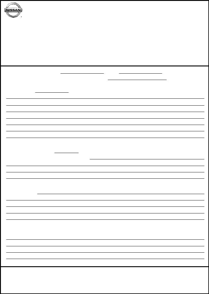
System Diagram |
INFOID:0000000006262704 |
NOTE: |
JMMIA0292GB |
|
|
• *1: TAIL LAMP switch links lighting switch 1ST position. |
|
• *2: “FR WIP INT/AT” is FR WIPER INT/AUTO. |
|
System Description |
INFOID:0000000006262705 |
OUTLINE
•BCM reads the status of the combination switch (light, turn signal, wiper and washer) and recognizes the status of each switch.
•BCM is a combination of 5 output terminals (OUTPUT 1 - 5) and 5 input terminals (INPUT 1 - 5). It reads a maximum of 20 switch status.
COMBINATION SWITCH MATRIX
Combination switch circuit
JMMIA0293GB
NOTE:
•*1: TAIL LAMP switch links lighting switch 1ST position.
•*2: “FR WIP INT/AT” is FR WIPER INT/AUTO.
Revision: 2011 November
BCS-10
2011 MURANO

COMBINATION SWITCH READING SYSTEM
< SYSTEM DESCRIPTION >
Combination switch INPUT-OUTPUT system list
System |
OUTPUT 1 |
OUTPUT 2 |
OUTPUT 3 |
OUTPUT 4 |
OUTPUT 5 |
|
|
|
|
|
|
|
|
INPUT 1 |
— |
FR WASHER |
FR WIPER LOW |
TURN LH |
TURN RH |
|
|
|
|
|
|
|
|
INPUT 2 |
FR WIPER HI |
— |
FR WIPER INT/ |
PASSING |
HEADLAMP 1 |
|
AUTO |
||||||
|
|
|
|
|
||
INPUT 3 |
WIP VOLUME 1 |
RR WASHER |
— |
HEADLAMP 2 |
HI BEAM |
|
|
|
|
|
|
|
|
INPUT 4 |
RR WIPER INT |
WIP VOLUME 3 |
AUTO LIGHT |
— |
TAIL LAMP |
|
|
|
|
|
|
|
|
INPUT 5 |
WIP VOLUME 2 |
RR WIPER ON |
— |
FR FOG |
— |
NOTE:
Headlamp has a dual system switch.
A
B
C
D
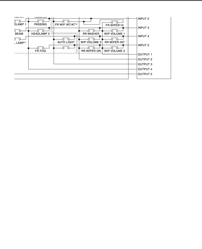
COMBINATION SWITCH READING FUNCTION
Description
• BCM reads the status of the combination switch at 10 ms interval normally.
JPMIA0067GB
NOTE:
BCM reads the status of the combination switch at 60 ms interval when BCM is controlled at low power consumption mode.
• BCM operates as follows and judges the status of the combination switch.
-INPUT 1 - 5 outputs the voltage waveforms of 5 systems simultaneously.
-It operates the transistor on OUTPUT side in the following order: OUTPUT 5 → 4 → 3 → 2 → 1.
-The voltage waveform of INPUT corresponding to the formed circuit changes according to the operation of the transistor on OUTPUT side if any (1 or more) switches are ON.
-It reads this change of the voltage as the status signal of the combination switch.
JPMIA0068GB
E
F
G
H
I
J
K
L
BCS
N
O
P
Revision: 2011 November
BCS-11
2011 MURANO
COMBINATION SWITCH READING SYSTEM
< SYSTEM DESCRIPTION >
Operation Example
In the following operation example, the combination of the status signals of the combination switch is replaced as follows: INPUT 1 - 5 to “1 - 5” and OUTPUT 1 - 5 to “A - E”.
Example 1: When a switch (TURN RH switch) is turned ON
• The circuit between INPUT 1 and OUTPUT 5 is formed when the TURN RH switch is turned ON.
JMMIA0294GB
•BCM detects the combination switch status signal “1E” when the signal of OUTPUT 5 is input to INPUT 1.
•BCM judges that the TURN RH switch is ON when the signal “1E” is detected.
Example 2: When some switches (turn RH switch, front wiper LO switch) are turned ON
•The circuits between INPUT 1 and OUTPUT 5 and between INPUT 1 and OUTPUT 3 are formed when the TURN RH switch and FR WIPER LOW switch are turned ON.
JMMIA0295GB
•BCM detects the combination switch status signal “1CE” when the signals of OUTPUT 3 and OUTPUT 5 are input to INPUT 1.
•BCM judges that the TURN RH switch and FR WIPER LOW switch are ON when the signal “1CE” is detected.
WIPER VOLUME DIAL POSITION
BCM judges the wiper volume dial 1 - 7 by the status of WIP VOLUME 1, 2 and 3 switches.
Wiper volume dial position |
|
Switch status |
|
|
|
|
|
||
WIP VOLUME 1 |
WIP VOLUME 2 |
WIP VOLUME 3 |
||
|
||||
|
|
|
|
|
1 |
ON |
ON |
ON |
|
|
|
|
|
|
2 |
ON |
ON |
OFF |
|
|
|
|
|
Revision: 2011 November
BCS-12
2011 MURANO

COMBINATION SWITCH READING SYSTEM
< SYSTEM DESCRIPTION >
Wiper volume dial position |
|
Switch status |
|
|
|
|
|
||
WIP VOLUME 1 |
WIP VOLUME 2 |
WIP VOLUME 3 |
||
|
||||
|
|
|
|
|
3 |
ON |
OFF |
OFF |
|
|
|
|
|
|
4 |
OFF |
OFF |
OFF |
|
|
|
|
|
|
5 |
OFF |
OFF |
ON |
|
|
|
|
|
|
6 |
OFF |
ON |
ON |
|
|
|
|
|
|
7 |
OFF |
ON |
OFF |
NOTE:
For details of wiper volume dial position, refer to WW-5, "WITH RAIN SENSOR : System Description" (with rain sensor), WW-9, "WITHOUT RAIN SENSOR : System Description" (without rain sensor).
A
B
C
D
E
F
G
H
I
J
K
L
BCS
N
O
P
Revision: 2011 November
BCS-13
2011 MURANO
SIGNAL BUFFER SYSTEM
< SYSTEM DESCRIPTION >
SIGNAL BUFFER SYSTEM
System Diagram |
INFOID:0000000006262706 |
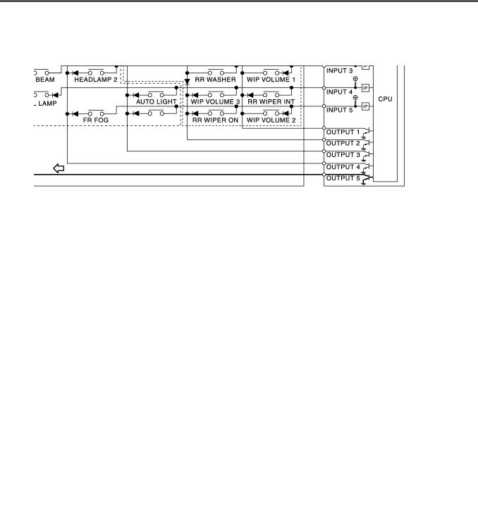
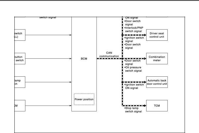
System Description
OUTLINE
JMMIA0298GB
INFOID:0000000006262707
BCM has the signal transmission function that outputs/transmits each input/received signal to each unit.
Signal transmission function list
Signal name |
Input |
|
Output |
Description |
|
|
|
|
|
|
|
|
|
• |
IPDM E/R (CAN) |
Inputs the push-button ignition |
|
|
|
switch (push switch) signal and |
|||
• Ignition switch ON signal |
Push-button ignition switch |
• Driver seat control unit (CAN) |
|||
transmits the ignition switch sta- |
|||||
• Ignition switch signal |
(Push switch) |
• |
Automatic back door control |
||
tus judged with BCM via CAN |
|||||
|
|
|
unit (CAN) |
||
|
|
|
communication. |
||
|
|
|
|
||
|
|
|
|
|
|
Door switch signal |
Any door switch |
• |
Combination meter (CAN) |
Inputs the door switch signal |
|
• |
IPDM E/R (CAN) |
and transmits it via CAN com- |
|||
|
|
• Driver seat control unit (CAN) |
munication. |
||
Oil pressure switch signal |
IPDM E/R (CAN) |
Combination meter (CAN) |
Transmits the received oil pres- |
||
sure switch signal via CAN |
|||||
|
|
|
|
communication. |
|
|
• Stop lamp switch |
|
|
Inputs the stop lamp switch 1 |
|
Stop lamp switch signal |
TCM (CAN) |
signal, and stop lamp switch 2 |
|||
• ICC brake hold relay (With |
signal or ICC brake hold relay |
||||
|
ICC) |
|
|
(with ICC) signal, and transmits |
|
|
|
|
|
it via CAN communication. |
|
|
|
|
|
Inputs the selector lever P/N po- |
|
Interlock/PNP switch signal |
TCM |
IPDM E/R (CAN) |
sition signal, and transmits the |
||
interlock/PNP switch signal via |
|||||
|
|
|
|
||
|
|
|
|
CAN communication. |
|
|
|
|
|
|
|
Revision: 2011 November
BCS-14
2011 MURANO
POWER CONSUMPTION CONTROL SYSTEM
< SYSTEM DESCRIPTION >
POWER CONSUMPTION CONTROL SYSTEM
System Diagram |
INFOID:0000000006262708 |
|
|
JPMIA0906GB |
|
System Description |
INFOID:0000000006262709 |
||
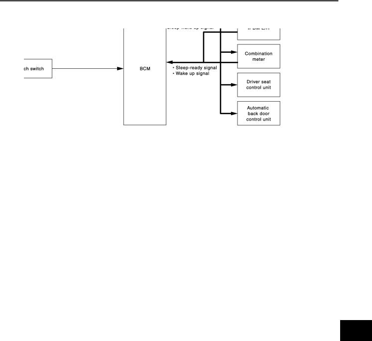
OUTLINE
•BCM incorporates a power saving control function that reduces the power consumption according to the vehicle status.
•BCM switches the status (control mode) by itself with the power saving control function. It performs the sleep request to each unit (IPDM E/R, combination meter, driver seat control unit and automatic back door control unit) that operates with the ignition switch OFF.
Normal mode (wake-up)
-CAN communication is normally performed with other units
-Each control with BCM is operating properly
CAN communication sleep mode (CAN sleep)
-CAN transmission is stopped
-Control with BCM only is operating
Low power consumption mode (BCM sleep)
-Low power consumption control is active
-CAN transmission is stopped
LOW POWER CONSUMPTION CONTROL WITH BCM
BCM reduces the power consumption with the following operation in the low power consumption mode.
• The reading interval of the each switches changes from 10 ms interval to 60 ms interval.
Sleep mode activation
•BCM receives the sleep-ready signal (ready) from IPDM E/R and combination meter via CAN communication.
•BCM transmits the sleep wake up signal (sleep) to each unit when all of the CAN sleep conditions are fulfilled.
•Each unit stops the transmission of CAN communication with the sleep wake up signal. BCM is in CAN communication sleep mode.
•BCM is in the low power consumption mode and perform the low power consumption control when all of the BCM sleep conditions are fulfilled with CAN sleep condition.
A
B
C
D
E
F
G
H
I
J
K
L
BCS
N
O
P
Revision: 2011 November
BCS-15
2011 MURANO

POWER CONSUMPTION CONTROL SYSTEM
< SYSTEM DESCRIPTION >
Sleep condition
CAN sleep condition |
BCM sleep condition |
|
|
• Receiving the sleep-ready signal (ready) from all units |
• Interior room lamp battery saver: Time out |
• Ignition switch: OFF |
|
• Vehicle security system and panic alarm: Not operation |
• RAP system: OFF |
• Warning chime: Not operation |
• Power window switch communication: No transmission |
• Intelligent Key system buzzer: Not operation |
• Push-button ignition switch illumination: OFF |
• Stop lamp switch: OFF |
• Nissan Vehicle Immobilizer System (NVIS) - NATS: Not opera- |
• Key slot (card switch) status: No change |
tion |
• Turn signal indicator lamp: Not operation |
• Remote keyless entry receiver communication status: No com- |
• Exterior lamp: OFF |
munication |
• Door lock status: No change |
• Tire pressure monitor system (TPMS) - AIR PRESSURE MON- |
• CONSULT-III communication status: Not communication |
ITOR: Stop |
• Meter display signal: Non-transmission |
• LOCK indicator lamp: Not operation |
• Door switch status: No change |
• ACC indicator lamp: Not operation |
• Rear window defogger: OFF |
• ON indicator lamp: Not operation |
• Auto back door: Not operation |
|
Wake-up operation
•BCM changes from the low power consumption mode to the CAN communication sleep mode when the any of the BCM wake-up conditions is fulfilled. Only the control with BCM is activated.
•BCM transmits the sleep wake up signal (wake up) to each unit when any of the CAN wake-up conditions is fulfilled. It changes from the low power consumption mode or the CAN communication sleep mode to the normal mode.
•Each unit starts the transmission of CAN communication with the sleep wake up signal. In addition, the combination meter transmits the wake up signal to BCM via CAN communication to report the CAN communication start.
Wake-up condition
BCM wake-up condition |
|
CAN wake-up condition |
|
|
|
||
|
• Receiving the sleep-ready signal (Not-ready) from any units |
||
|
• |
Key slot (key switch): OFF → ON, ON → OFF |
|
|
• |
Push-button ignition switch (push switch): OFF→ ON |
|
|
• |
Hazard switch: OFF → ON |
|
|
• |
PASSING switch: OFF → ON, ON → OFF |
|
|
• |
TAIL LAMP switch: OFF → ON |
|
• Power window switch communication: Receiving |
• |
Driver door switch: OFF → ON, ON → OFF |
|
• |
Passenger door switch: OFF → ON, ON → OFF |
||
• Remote keyless entry receiver communication: Receiving |
|||
• |
Rear RH door switch: OFF → ON, ON → OFF |
||
|
|||
|
• |
Rear LH door switch: OFF → ON, ON → OFF |
|
|
• |
Back door switch: OFF → ON, ON → OFF |
|
|
• |
Driver door request switch: OFF → ON |
|
|
• |
Passenger door request switch: OFF → ON |
|
|
• |
Back door request switch: OFF → ON |
|
|
• |
Stop lamp switch: ON |
|
Revision: 2011 November
BCS-16
2011 MURANO

POWER CONSUMPTION CONTROL SYSTEM
< SYSTEM DESCRIPTION >
Component Parts Location |
|
|
INFOID:0000000006262710 |
A |
|||
|
|
|
|
|
|
|
|
|
|
|
|
|
|
|
B |
|
|
|
|
|
|
|
|
|
|
|
|
|
|
|
C |
|
|
|
|
|
|
|
D |
|
|
|
|
|
|
|
E |
|
|
|
|
|
|
|
F |
|
|
|
|
|
|
|
G |
|
|
|
|
|
|
|
H |
|
|
|
|
|
|
|
I |
|
|
|
|
|
|
|
J |
|
|
|
|
|
|
|
K |
|
|
|
|
|
|
|
L |
|
|
|
|
|
|
|
|
|
|
|
|
|
JPMIA0899ZZ |
|
BCS |
|
|
|
|
|
|
|
|
1. |
Combination meter |
2. |
IPDM E/R |
3. BCM |
N |
||
4. |
Driver seat control unit |
5. Automatic back door control unit |
|
|
|||
A. |
Engine room (LH) |
B. |
Behind of combination meter |
C. Backside of the seat cushion (driver |
|
||
|
|
|
|
|
seat) |
|
|
D. |
Dash side lower (Passenger side) |
|
|
|
|
O |
|
P
Revision: 2011 November
BCS-17
2011 MURANO

DIAGNOSIS SYSTEM (BCM)
< SYSTEM DESCRIPTION >
DIAGNOSIS SYSTEM (BCM)
COMMON ITEM
COMMON ITEM : CONSULT-III Function (BCM - COMMON ITEM) |
INFOID:0000000006262711 |
APPLICATION ITEM
CONSULT-III performs the following functions via CAN communication with BCM.
Diagnosis mode |
Function Description |
|
|
|
|
Work Support |
Changes the setting for each system function. |
|
|
|
|
Self Diagnostic Result |
Displays the diagnosis results judged by BCM. |
|
|
|
|
CAN Diag Support Monitor |
Monitors the reception status of CAN communication viewed from BCM. Refer to CONSULT-III opera- |
|
tion manual. |
||
|
||
Data Monitor |
The BCM input/output signals are displayed. |
|
|
|
|
Active Test |
The signals used to activate each device are forcibly supplied from BCM. |
|
|
|
|
Ecu Identification |
The BCM part number is displayed. |
|
|
|
|
Configuration |
• Read and save the vehicle specification. |
|
• Write the vehicle specification when replacing BCM. |
||
|
SYSTEM APPLICATION
BCM can perform the following functions for each system.
NOTE:
It can perform the diagnosis modes except the following for all sub system selection items.
|
|
|
|
|
×: Applicable item |
|
|
System |
Sub system selection item |
|
Diagnosis mode |
|
|
|
|
|
|
|||
|
Work Support |
Data Monitor |
Active Test |
|||
|
|
|
||||
|
|
|
|
|
||
Door lock |
DOOR LOCK |
× |
× |
× |
||
|
|
|
|
|
||
Rear window defogger |
REAR DEFOGGER |
|
× |
× |
||
|
|
|
|
|
||
Warning chime |
BUZZER |
|
× |
× |
||
|
|
|
|
|
||
Interior room lamp timer |
INT LAMP |
× |
× |
× |
||
|
|
|
|
|
||
Exterior lamp |
HEAD LAMP |
× |
× |
× |
||
|
|
|
|
|
||
Wiper and washer |
WIPER |
× 1 |
× |
× |
||
|
|
|
* |
|
|
|
Turn signal and hazard warning lamps |
FLASHER |
× |
× |
× |
||
|
|
|
|
|
|
|
|
— |
AIR CONDITONER*2 |
|
|
|
|
• |
Intelligent Key system |
INTELLIGENT KEY |
× |
× |
× |
|
• |
Engine start system |
|||||
|
|
|
|
|||
Combination switch |
COMB SW |
|
× |
|
||
|
|
|
|
|
||
Body control system |
BCM |
× |
|
|
||
|
|
|
|
|
||
NVIS - NATS |
IMMU |
|
× |
× |
||
|
|
|
|
|
||
Interior room lamp battery saver |
BATTERY SAVER |
× |
× |
× |
||
|
|
|
|
|
||
Back door opener system |
TRUNK |
|
× |
× |
||
|
|
|
|
|
||
Vehicle security system |
THEFT ALM |
× |
× |
× |
||
|
|
|
|
|
||
RAP system |
RETAINED PWR |
|
× |
|
||
|
|
|
|
|
||
Signal buffer system |
SIGNAL BUFFER |
|
× |
× |
||
|
|
|
|
|
||
TPMS |
TPMS (AIR PRESSURE MONITOR) |
× |
× |
× |
||
|
|
|
|
|
|
|
NOTE:
•*1: For models with rain sensor this mode is displayed, but is not used.
•*2: This item is displayed, but is not used.
FREEZE FRAME DATA (FFD)
Revision: 2011 November
BCS-18
2011 MURANO
 Loading...