


Pulsar N13 1989
Table of contents
 Loading...
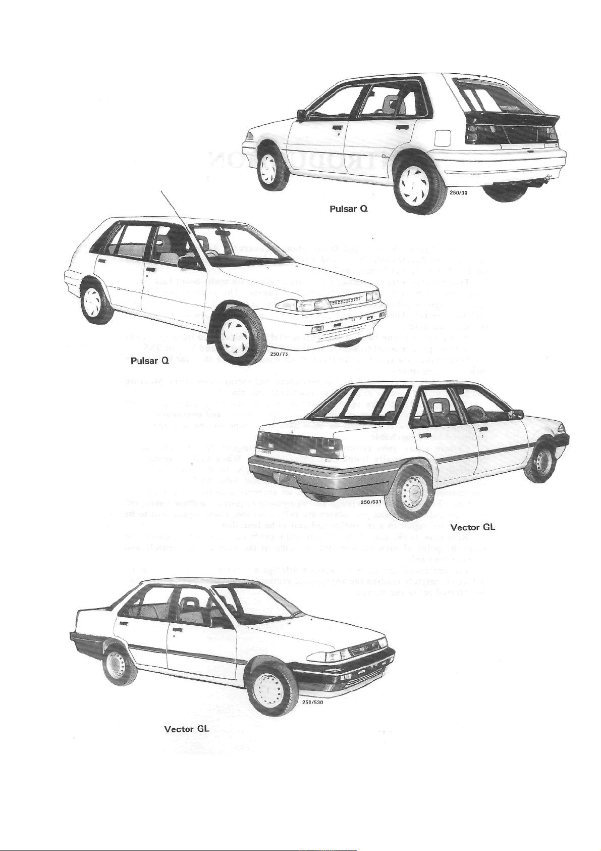
VEHICLE IDENTIFICATION AND
GENERAL SPECIFICATIONS
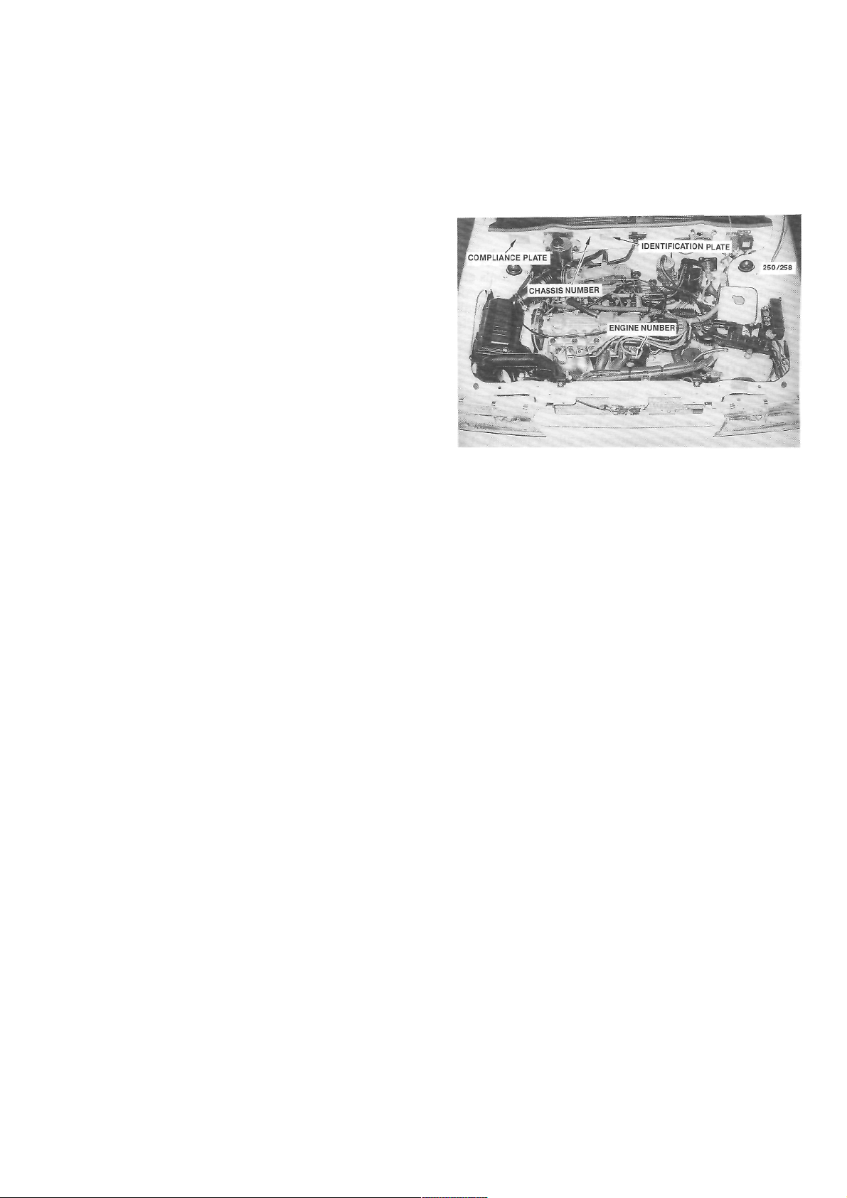
1. VEHICLE IDENTIFICATION
When purchasing spare parts or when
registering
or insuring a vehicle, it may be necessary to quote
various vehicle identification codes. The location of
these codes are as follows:
The Engine Number is stamped on the front
face
of the engine block below No. 4 spark plug.
The Chassis Number is stamped on the bulkhead
above and to the right of the brake booster.
The Vehicle Identification Plate is located on the
bulkhead to the left of the MAP sensor and contains
codings relating to body style, engine capacity,
model,
transaxle type, engine number, paint, trim and build
date.
The Compliance Plate contains information on
the vehicle make, model, month and year of manufacture, chassis number, seating, capacity and the
Australian Design Rules (ADR) with which the vehicle complies. This plate is affixed to the bulkhead
above and to the left of the brake booster.
The Tire Placard, which is located on the inside
of the glove compartment, contains information
on
the tire size, rim size, tire pressure and load ratings.
2. GENERAL VEHICLE SPECIFICATIONS
Length:
Pulsar...................................................4 030 mm
Astra hatchback ..................................4 035 mm
Vector ..................................................4215 mm
Astra sedan..........................................4 255 mm
Width:
Nissan .................................................. 1 640 mm
Holden ................................................. 1 655 mm
Height ........................................................ 1 380 mm
Wheelbase..................................................2 430 mm
Wheel track:
Front .................................................... 1 435 mm
Rear ..................................................... I 430 mm
View of the engine compartment showing the location
of various vehicle identification information.
Minimum ground clearance:
Nissan.................................................... 128 mm
Holden................................................... 110 mm
Turning circle kerb to kerb .......................... 10.8 m
Fuel tank capacity:
Nissan.................................................... 47 liters
Holden................................................... 50 liters
Towing capacity:
Without trailer brakes............................ 400 kg
With trailer brakes................................. 900 kg
*Fuel consumption:
L/100km L/100km
(City) (Highway)
Manual transaxle 8.5 6.6
Automatic transaxle 9.0 7.2
*The fuel consumption information is based on
tests made according to Australian Standard 2877.
The actual fuel consumption will depend on many
factors including driving habits, vehicle condition
and equipment and the prevailing conditions.
GENERAL INFORMATION
1. TOOLS AND EQUIPMENT
To successfully perform any maintenance or repair work on a motor vehicle, suitable hand tools are
essential. The use of tools for other than their intended purpose or the use of incorrectly fitting tools can
cause damage to the component and/or injury lo the
operator.
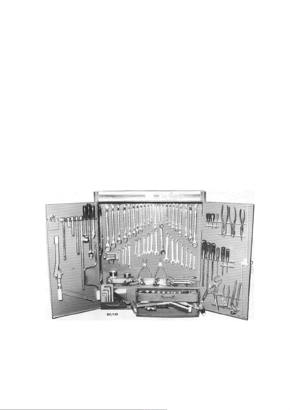
BASIC TOOL KIT
equipment for the majority of the maintenance and
repair procedures described in this manual. Of course,
not all of the tools are required for all the jobs, so it is
wise to purchase tools on an 'as needed' basis.
The following is a suggested list of tools and
Set of open ended spanners.
Set of ring spanners.
Set of socket spanners.
Spark plug spanner.
Assorted bladed screwdrivers.
Assorted Philips screwdrivers.
Assorted pliers — combination, long nose, multigrip, vice grip, snap ring (internal and external).
Assorted adjustable spanners.
Ball pein hammer.
Cold chisels.
Pin punches and centre punch.
Assorted files.
Scraper.
Feeler gauges.
Torque wrench.
Hydraulic jack.
Chassis stands.
Car ramps.
Grease gun.
Oil can.
Oil gun.
Oil filter removal tool.
Funnel.
Containers for draining oil and washing components.
A comprehensive tool kit showing a wide range of general hand tools.
General Information
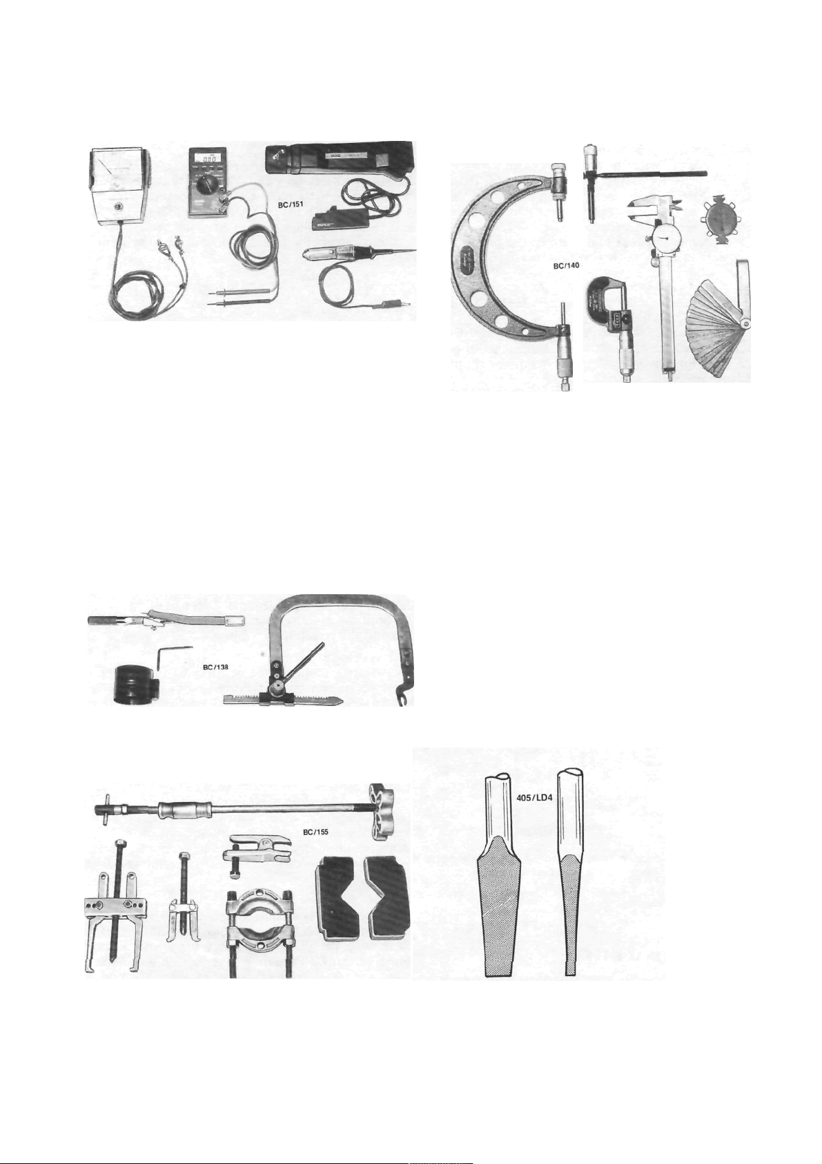
Assorted test equipment — dwell tachometer, digital
multimeter, timing light and test lamp.
Inspection lamp.
Test lamp.
Tachometer.
Timing light.
Digital multimeter.
Piston ring compressor.
Valve spring compressor.
Micrometer — inside, outside, multi range.
Vernier calipers.
Assorted pullers.
When purchasing tools, it is sound advice to select
the highest quality that can be afforded, as the
working life of cheaper tools is often very short.
Assorted measuring devices — inside and outside
micrometers, vernier calipers, wire gauges and feeler
Ensure that the tools are suitable for the system of
bolt and nut sizing on the vehicle. The range of
vehicles covered by this manual use metric sizes.
TOOL CARE
To ensure the longest possible life for hand tools,
it is important that time be spent maintaining them.
At the conclusion of each job. all tools used should
be washed thoroughly in kerosene or similar cleaning
solvent. Ensure that all dirt and grease is removed,
particularly from tools with moving parts such as
pliers and adjustable spanners. The tools should then
be wiped dry with a clean cloth.
Measuring devices should be given particular
attention as their accuracy can be affected if not
properly maintained. Feeler gauges should be kept
clean at all times and the blades should be wiped with
an oily cloth after use to prevent rusting.
gauges.
Tension wrench, piston ring compressor and valve
spring compressor.
Slide hammer, ball joint puller, assorted pullers and
press plates.
Views showing the correct tip profiles for a bladed
screwdriver. Bladed screwdrivers should not be
ground to a sharp point.

10
General Information
If tools are to be stored for any length of time, it is
good policy to wipe them with an oily cloth.
Bladed screwdrivers should be checked for damage to the tip. If necessary, the tip can be returned to
its original profile by careful grinding. Do not grind
screwdriver tips to a sharp point.
Hammer heads should be secure on their handles
and should be regularly checked for cracking or other
damage.
Chisels and punches should be checked for damage or 'mushrooming' of the head. Any faults should
be rectified by grinding.
Hydraulic jacks should be regularly checked for
fluid leaks. Chassis stands and car ramps should be
checked for damage and cracks. Any equipment that
is suspect should not be used.
STORES
For routine maintenance, stores of automotive
oils, greases and additives should be kept on hand.
The following is a suggested list.
Engine oil.
Brake fluid.
Manual transmission or automatic transmission
oil — automatic transmission oil is also used in
the power steering system.
Rear axle oil.
Cooling system corrosion inhibitor/antifreeze.
Chassis grease.
High melting point grease, for hub bearings etc.
Penetrating oil or spray.
Kerosene or similar cleaning solvent.
Methylated spirits.
Oils and greases are available in handy pack size for
do-it-yourself lube jobs.
2. SAFETY
PERSONAL SAFETY
Safety when working on a motor vehicle is basically a matter of commonsense. Some safety precautions
to prevent personal injuries are as follows.
Raising a Vehicle
Always jack a vehicle on firm, level ground and at
the specified jacking points. Ensure that the wheels
remaining on the ground are fully chocked.
After raising the vehicle, place chassis stands
underneath and allow the weight of the vehicle to rest
on them. Do not use bricks, blocks of wood or similar
material.
NOTE: Never work under a vehicle which is
only supported by a jack.
Electrical System
Always disconnect the negative battery terminal
when working on any electrical components. Avoid
wearing metal watches, rings and chains which may
short across live terminals.
As battery gases are explosive, keep naked flames
and sparks clear of the work area. When connecting
and disconnecting jumper leads, use extreme caution
to avoid sparking.
Electronic Ignition Systems
Electronic ignition systems produce dangerous
high tension voltages in both the primary and secondary circuits which can be fatal. Exercise extreme
caution when working on or near any ignition system
components. Do not disconnect high tension leads
while the engine is running.
Work Area
Do not run the engine in a confined space. Ensure
that the work area is adequately ventilated.
Spilt oil or water should be cleaned immediately
to avoid the possibility of slipping.
Fuel System
Always disconnect the negative battery terminal
when working on any fuel components. Do not smoke.
Keep naked flames and sparks clear of the work area.
Do not siphon fuel using the mouth. Use a hand
pump or suitable siphon.
Do not attempt to repair a fuel tank by welding it.
This is an extremely hazardous procedure and should
be entrusted to a specialist.
Cooling System
To avoid scalding, use caution when releasing the
radiator cap on an engine which is at normal operating
temperature. Turn the cap anti-clockwise to the first
stop and allow any pressure in the system to release.
When the pressure is released, remove the cap from
the radiator.
Brakes
As asbestos is used in some brake lining material,
avoid inhaling brake dust. Do not use compressed air
to remove the dust. Gentle brushing with a small
brush or using a vacuum cleaner with a hose attachment are the safest methods of cleaning the brakes.
The above precautions also apply to the clutch plate
lining material.
General Information
11
Lifting Equipment
When using lifting equipment to lift heavy components such as the engine and/or transmission, use
metal slings or chain in preference to rope. If rope
must be used, ensure that it is not placed against sharp
edges on the component.
Automotive Lubricants and Solvents
Avoid prolonged skin contact with oils, greases
and solvents as some can cause skin irritations and
dermatitis.
Exercise caution when using cleaning solvents as
many are inflammable. Do not smoke. Keep naked
flames and sparks clear of the work area.
Compressed Air
Never point an air hose at another person or allow
compressed air to blow onto your skin. High pressure
air forced against the skin can enter the bloodstream
and prove fatal.
Suspension and Steering Components
Damaged suspension and steering components
should not be welded. Many of these components are
fabricated from toughened metals. If welded they may
lose their strength or become brittle. Damaged components should be renewed.
Air Conditioning
Avoid disconnecting air conditioning hoses as
escaping refrigerant can cause frostbite. The refrigerant is highly flammable and when burnt, a poisonous
gas is produced.
VEHICLE SAFETY
To prevent damage to the vehicle during servicing
or repair work, note the following precautions.
Brake Fluid
If spilt on the vehicle paintwork, brake fluid
should be immediately washed away with clean water
and allowed to dry naturally, not wiped with a cloth.
Catalytic Converter
The following should be observed to prevent
damage to the catalytic converter:
Do not operate the vehicle on leaded fuel.
Do not push or tow start the vehicle.
Do not allow the engine to idle for prolonged
periods.
Do not switch the ignition off while the vehicle is
in motion and the transmission is in gear.
Do not 'prime' the engine by pouring fuel into the
inlet manifold.
Do not operate the vehicle if the engine is
misfiring.
Avoid running the vehicle out of fuel.
Ensure that the engine oil is formulated to contain
low phosphorus levels.
Electronic Components
The electronic components of the ignition and
fuel injection systems can be damaged by the use of
incorrect testing equipment.
It is essential in all tests where voltage or resistance is to be measured that a digital display multimeter with a minimum 10 megohm input impedance
be used.
Some types of tachometers, timing lights and
ignition system analyzers are not compatible with
certain engine electronic systems. It is therefore
recommended that the manufacturer of the test equipment be consulted before using the equipment.
Jump starting, or being jump started by another
vehicle can cause damage to the electronic components of the vehicle. Refer to the Roadside Trouble
shooting section for the correct jump starting procedure.
3. GENERAL REPAIR PROCEDURES
SEIZED FASTENERS
Seized bolts, nuts or screws should first have a
liberal amount of penetrating oil applied. The fastener
should be left for a period of time to allow the oil to
penetrate and soften the corrosion which is causing
the binding.
Often, a sharp hammer blow to the head of the
fastener can dislodge the corrosion and permit it to be
loosened.
An impact driver, which can be fitted with a
socket or screwdriver bit, can be used to loosen a
seized fastener.
Another method is to heat the component in
which the fastener is seized. However, extreme caution should be exercised when heating aluminum
alloy components as the melting point is much lower
than that of steel.
If the above methods fail to free a seized nut,
carefully hacksaw through one side of the nut until it
can be split. Care should be taken that the threads of
the bolt or stud are not damaged.
Should a bolt or stud break below the surface of
the component, it will be necessary to use a screw
extractor to remove the remaining part. Follow the
screw extractor manufacturers instructions.
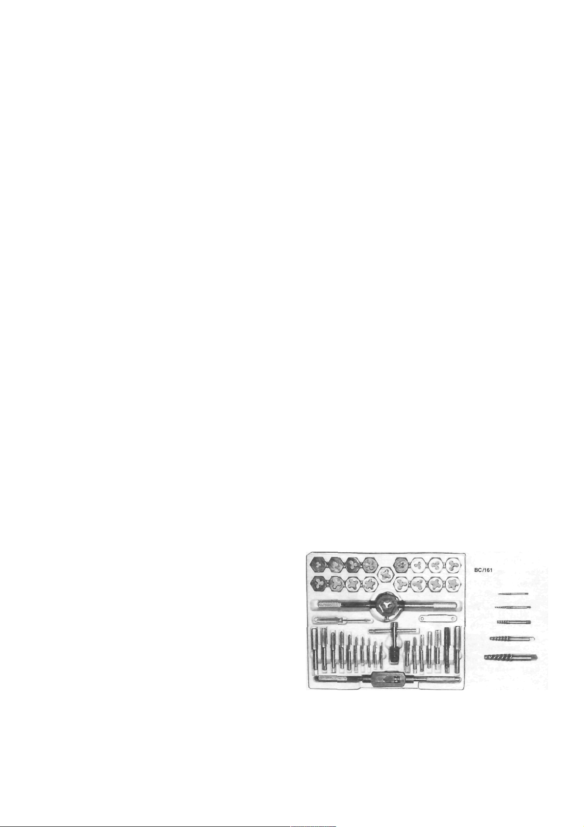
Tap and die set and assorted screw extractors.
12
General Information
Damaged threads can be repaired using a die nut
on studs and bolts, and a tap on nuts and threaded
holes in castings. If the threads of a threaded hole are
damaged beyond repair, it will be necessary to drill
and tap the hole to a larger size. Alternatively, a
Helicoil insert can be used to Testore the hole to the
original thread size.
STUDS
The simplest method for removing studs is to lock
two nuts together on the threaded section. The stud
should then be able to be removed by applying an
unscrewing action to the lower nut.
Alternatively, there are various makes of stud
extracting tools available.
similar levers between the components in an attempt
to lever them apart. This can cause severe damage to
the sealing surfaces, particularly if the components are
made of alloy compounds.
The components can be separated by tapping
along the joint with a soft faced hammer or piece of
wood. Before installing a new gasket, the mating
surfaces should be cleaned of all traces of old gasket
material and sealant.
Check that the new gasket is correct by comparing
the bolt holes and passages on the component face
with the openings in the gasket.
Cork and paper gaskets which have been stored
for some time may suffer from shrinkage. This can be
rectified by soaking the gasket in water.
BEARINGS AND BUSHES
If the correct equipment is not available when
removing and installing bearings and bushes, it is
often possible to improvise.
Bearings can often be removed from shafts by
tapping alternately on opposite sides with a hammer
and drift.
Using two nuts locked together to remove a stud.
OIL SEALS
Oil seals can usually be removed by levering out
with a flat screwdriver or other suitable lever. Care
should be taken not to damage the surface of the
component which the seal lip runs on.
Seals can also be removed by inserting a number
of self tapping screws into the seal body. The seal can
then be withdrawn using pliers gripping the self
tapping screws.
Always apply a smear of grease or oil to the seal lip
prior to installation to provide initial lubrication.
Unless otherwise stated, oil seals should always be
installed with the lip facing inwards or towards the
substance to be sealed. During installation, the seal li p
should be protected from damage from sharp components such as shaft splines by wrapping tape around
the sharp edges.
Install the new seal using a wooden block, or a
socket or length of tube of the appropriate diameter.
Ensure that the seal is installed squarely or distortion
and subsequent leakage may occur. If an installation
depth is not specified, the seal should be installed
flush with the component surface.
GASKETS
When separating mating components (i.e.
cylinder
head and cylinder block), do not insert screwdrivers or
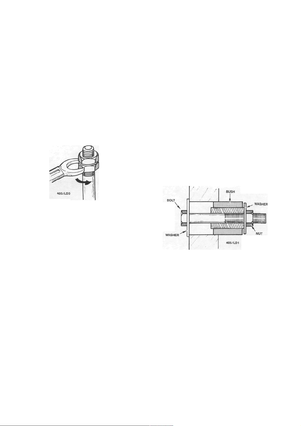
A simple bush installing tool using a bolt, nut and two
washers.
If a press is unavailable, bushes can be installed by
placing the bush and component between the jaws of a
vice and screwing the jaws together until the bush is
fully inserted. A vice can also be used to remove
bushes by using suitably sized spacers against either
vice jaw, one bearing on the bush and the other on the
component. This method can also be used with a G
clamp.
A simple removing and installing tool can be
made using a long bolt, large and small washers, a nut
and a tubular spacer. Refer to the illustrations for the
method and applications.
Rubber bushes and bushes in blind holes can be
removed using an expanding type masonry bolt
(Rawlbolt Loxin). Install a neat fitting masonry bolt to
the bush. Install and tighten the bolt until it grips the
bush. The bolt and bush can then be removed using a
slide hammer or levers.
General Information
13
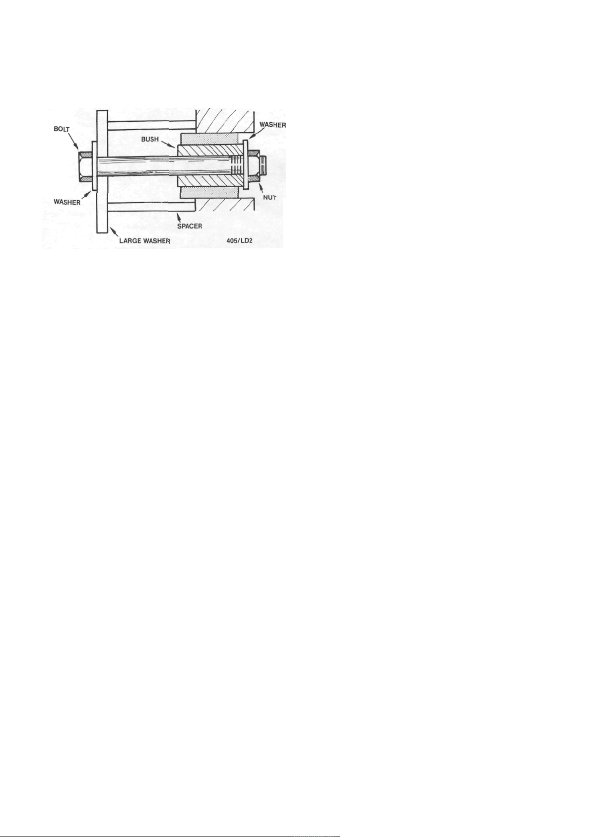
A simple bush removing tool using a bolt, nut, suitable
spacer and large and small washers.
Bushes in blind holes can also be removed using
hydraulic force. With the hole packed with grease,
insert a neat fitting drift and tap the drift into the hole.
The pressure of the grease on the rear of the bush
should force it from the hole.
ROTATING THE CRANKSHAFT
There are many occasions when it is necessary to
rotate the crankshaft to a certain position. These
include timing and valve adjustment and checking
valve timing.
To make the engine easier to rotate, remove the
spark plugs. This will relieve compression pressure.
The simplest method is to use a socket or ring
spanner on the crankshaft pulley nut and turn the
engine in the normal direction of rotation.
On vehicles with manual transmission, the engine
can be turned by selecting top gear and rolling the
vehicle forward. A variation of this method is to raise
one of the driving wheels and, with top gear selected,
rotate the driving wheel in a forward direction to turn
the engine.
Alternatively, the engine can be brought to the
desired position by briefly actuating the starter motor.
14
LUBRICATION AND MAINTENANCE
SPECIFICATIONS
CAPACITY AND GRADE
Engine:
Lubricant........................................... 15W-50 SF
Sump capacity including filter ........... 3.3 liters
Cooling system capacity............................ 6.0 liters
Manual transaxle:
Lubricant.......................................80W-90 GL-4
Capacity ............................................... 2.7 liters
Automatic transaxle:
Lubricant.............................................. Dexron II
Capacity ............................................... 6.0 liters
Power steering:
Lubricant.............................................. Dexron II
Capacity ............................................... 1.0 liters
Manual steering lubricant........ Castrol EPLl grease
Brake fluid type ................................................ Dot 4
1. HOW TO GREASE AND OIL CHANGE
(1) Run the front of the vehicle onto car ramps
and stop the engine. Chock the front wheels.
(2) Raise the rear of the vehicle and place
chassis stands under the rear jacking points.
NOTE: It is best if the vehicle is kept as level
as possible to avoid false readings when
checking the lubricant levels.
(3) Clean around the engine sump drain plug.
(4) Place a drain tin under the engine sump,
remove the engine sump drain plug and allow the
engine sump to completely drain.
NOTE: It is best to drain the engine sump
with the oil at operating temperature. However, if the oil is hot take care to avoid
scalding.
(5) Check that the sealing gasket on the sump
plug is in a serviceable condition.
(6) When the engine sump has completely
drained, install and firmly tighten the sump drain plug.
Wipe around the plug after installation.
(7) Place the drain tin under the oil filler,
remove the oil filter using a filter removal tool and
allow the residual engine oil to drain. Smear the
scaling ring of the new filter with engine oil and
lighten the filter by hand as per the instructions
supplied with the new filter.
NOTE: Before installing the new filter, ensure that the sealing gasket from the old
filter has not adhered to the filter sealing
surface on the engine.
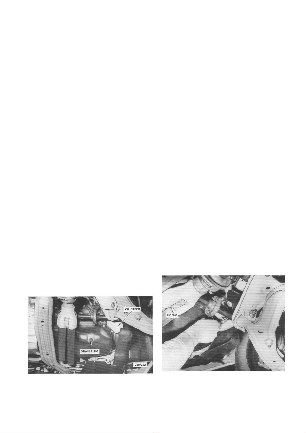
(8) Remove the lev el chec king pl ug from the
Location of the engine sump drain plug.
Removing the engine oil filter using a filter removal tool.
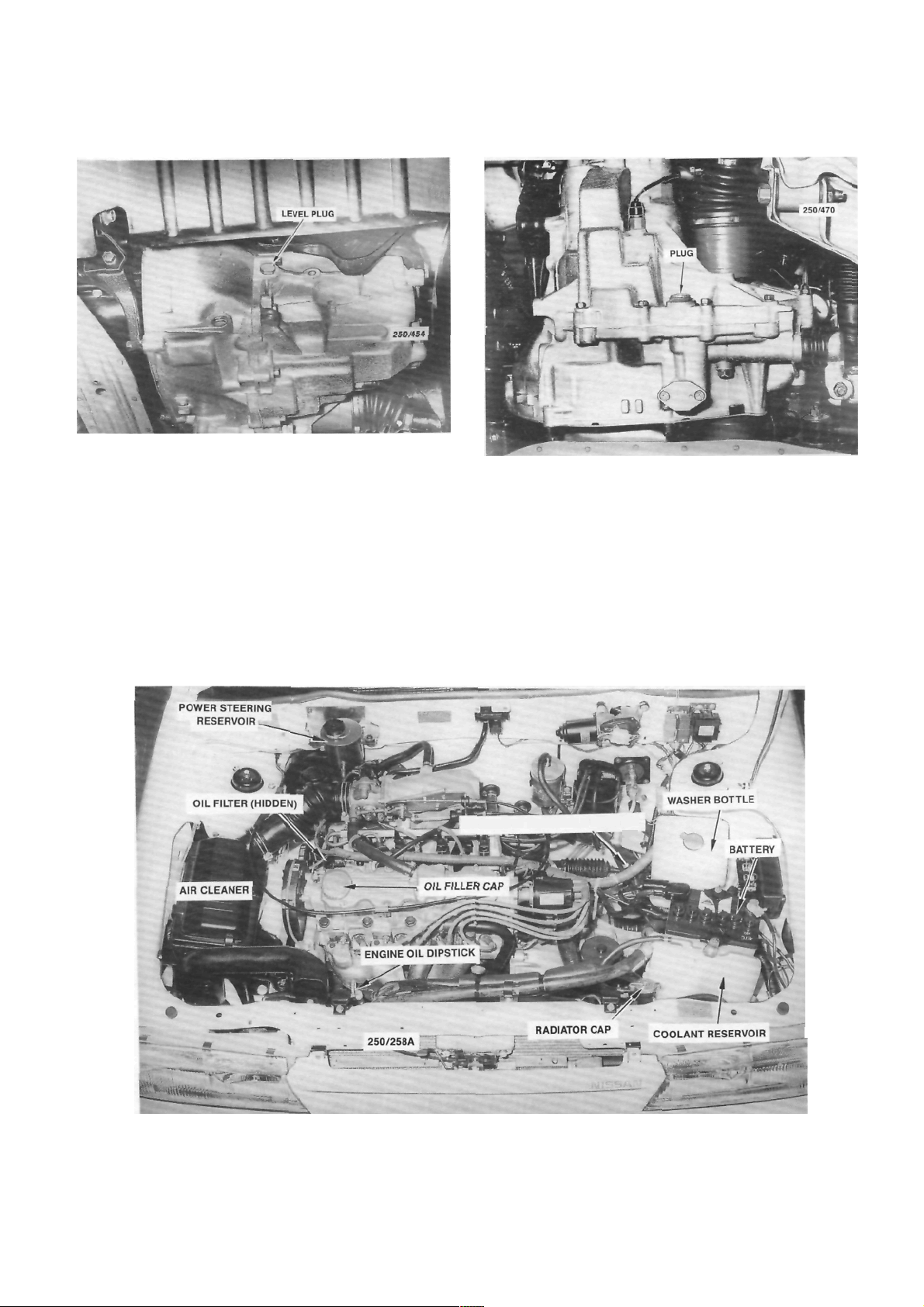
Lubrication and Maintenance
Location of the manual transaxle level plug.
manual transaxle. Using a finger, check that the oil is
level with the bottom of the plug hole. Overfilled units
should be drained to the correct level.
If the oil level is low, use an oil gun to fill the
transaxle to the correct level.
When satisfied that the oil level is correct, install
the plug and tighten firmly. Wipe around the plug
after installation.
NOTE: On automatic transaxle vehicles,
refer to the Automatic Transaxle section for
the checking and topping up procedure.
Location of the manual transaxle drain plug.
(9) Using a funnel, fill the engine with the
specified amount and grade of engine oil. start the
engine and run it for a few minutes. Ensure that the
oil light goes out. Stop the engine, wait for a few
minutes and check the engine oil on the dipstick. If
necessary add oil to bring the level to the full mark on
the dipstick.
NOTE: To prevent overfilling the engine
initially, it is good policy not to pour all the
15
AUTOMATIC TRANSAXLE DIPSTICK
Underbonnet view of the 1.8 liter engine. Automatic transaxle model.
r
16
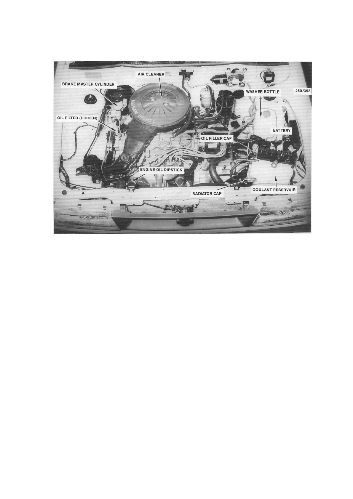
Lubrication and Maintenance
Underbonnet view of the 1.6 liter engine. Manual transaxle model.
oil into the engine in one go as sometimes
the amounts specified are only approximate.
If is best to hold back at least half a liter and
top up the level after the engine has been run
for a few minutes.
(10) Check thoroughly for oil leaks at the engine
sump drain plug and oil filter if a new filter was
installed.
(11) Referring to the service schedule, lubricate
and check all other items which coincide with the
grease and oil change intervals.
(12) Lower the vehicle to the ground.

Lubrication and Maintenance 17
2. SERVICE SCHEDULE
This Section Removed

18
Lubrication and Maintenance
This Section Removed

Lubrication and Maintenance
19
This Section Removed

20
Lubrication and Maintenance
This Section Removed
WHEELS AND TYRES
SPECIFICATIONS
TYRES PRESSURES
Front:
Normal load ............................................ 200 kPa
Heavy load or high speed ......................230 kPa
Rear:
Normal load ............................................ 180 kPa
Heavy load or high speed ...................... 210 kPa
NOTE: The above pressures are measured
cold and are meant as a guide only. Always
refer to the tire placard positioned on the
inside of the glove compartment lid and the
tire manufacturers recommendations first.
TORQUE WRENCH SETTINGS
Wheel nut torque .............................................98 Nm
1. HOW TO CHANGE A ROAD WHEEL
(4) Apply the handbrake firmly and chock the
front and rear of the wheel diagonally opposite the
wheel being changed.
(5) Remove the spare wheel, tool kit and jack
located in the luggage compartment.
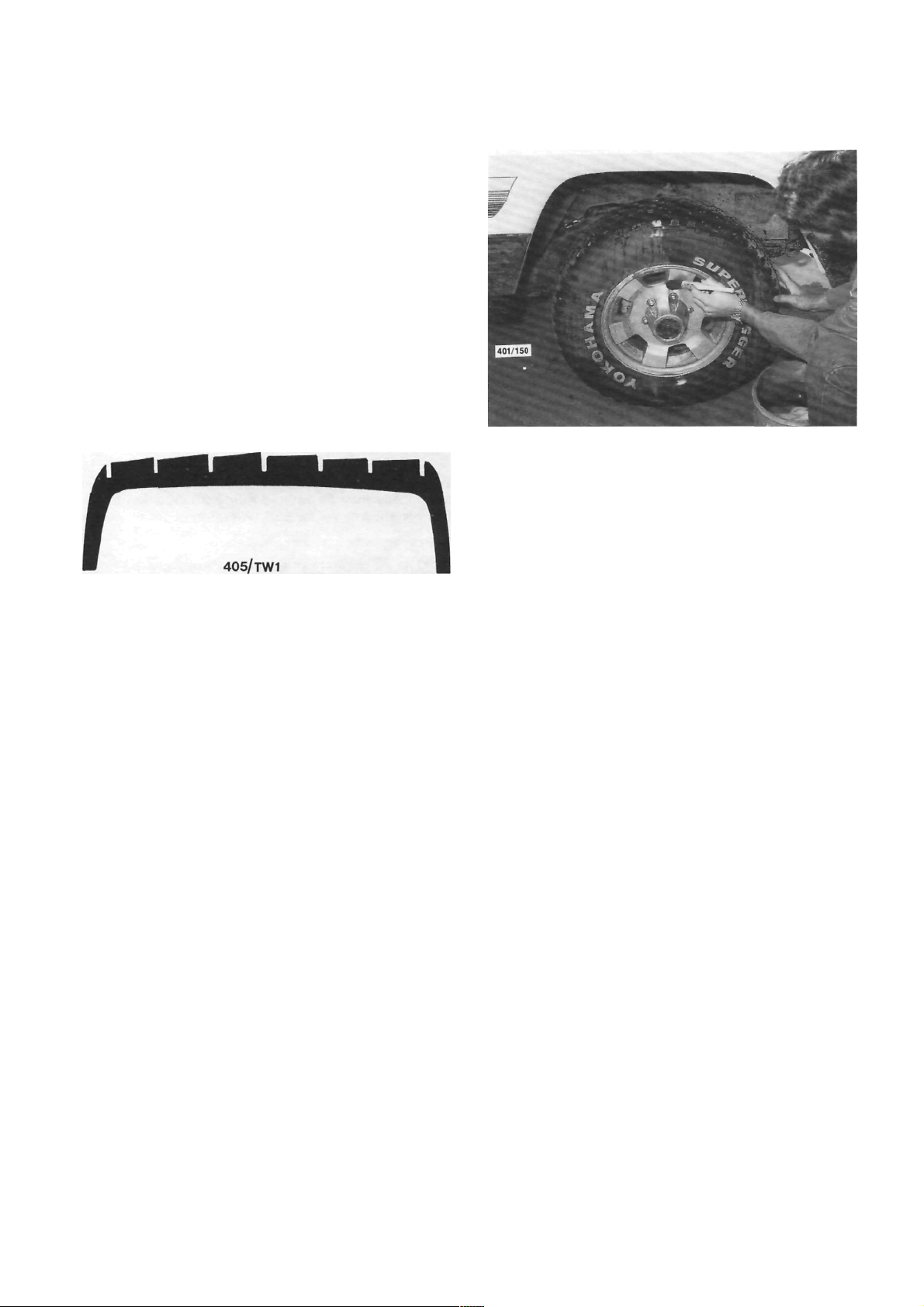
(6) On vehicles equipped with full wheel covers,
remove the trim from the wheel.
(7) Using the wheel spanner, loosen the wheel
nuts progressively in a diagonal sequence half a turn.
(8) Position the jack under the jacking point
closest to the wheel being removed and raise the jack
until the head of the jack contacts the jacking point.
(9) Raise the vehicle slightly and check that the
jack is stable and vertical.
(1) Ensure that the vehicle is on level firm
ground and clear of any passing traffic.
(2) If necessary, switch on the hazard
flashers.
(3) Switch off the engine and place the transaxle
in the (P) Park position on automatic transaxle
models or in reverse gear on manual transaxle models.
Chock the front and rear of the wheel diagonally
opposite the wheel being changed.
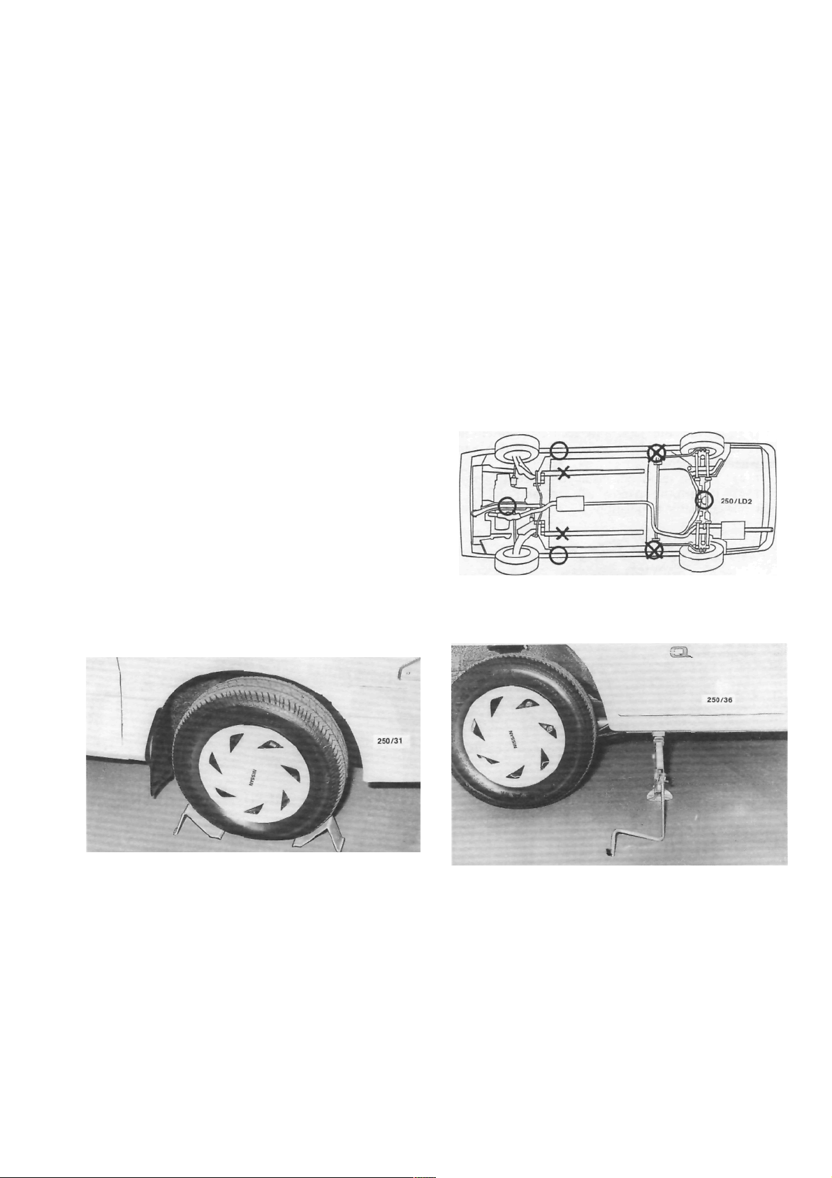
Underbody view showing the jacking and supporting
points. O indicates the jacking points and X indicates
the supporting points.
View of the jack correctly installed to the rear jacking
point.
22
View of the jack correctly installed to the front jacking
point
.
Wheels and Tires
(10) Continue to raise the jack until the tire
clears the ground sufficiently to allow the spare wheel
to be installed.
(11) Remove the wheel nuts and lift the wheel
off the hub.
NOTE: Under no circumstances get under
the vehicle while the jack is the only means
of support.
(12) Install the spare wheel and install the wheel
nuts with the chamfered ends contacting the wheels.
Tighten the wheel nuts as much as possible by hand.
(13) Lower the jack and securely tighten the
wheel nuts progressively in a diagonal sequence using
the wheel spanner.
(14) Where removed, install the wheel cover.
(15) Return the spare wheel, jack and tool kit to
their relevant storage positions.
ABNORMAL WEAR ON CENTRE OF TREAD
(1) Over inflation of tires: Check and reduce to
the recommended pressure.
ABNORMAL WEAR ON INSIDE OF TREAD
(1) Excessive negative camber angle: Check the
wheel alignment.
(2) Sagging coil springs: Check and renew the
coil springs as a pair.
(3) Loose or worn hub bearing assembly: Check
and renew the hub bearing assembly.
(4) Bent, loose or worn suspension components:
Check and renew any faulty components.
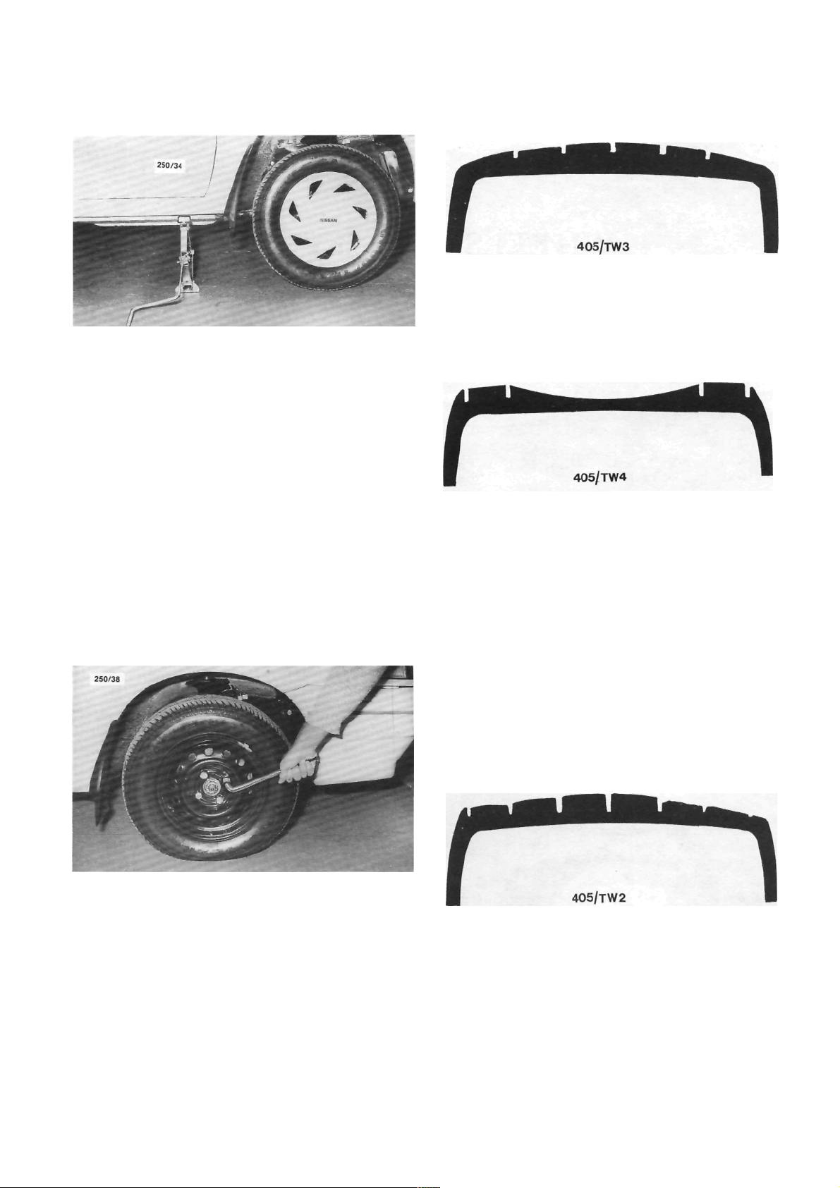
Tighten the wheel nuts in a diagonal sequence using
the wheel spanner.
2. TYRE WEAR TROUBLE SHOOTING
ABNORMAL WEAR ON BOTH SIDES OF
TREAD
(1) Under inflation of tires: Check and inflate to
the recommended pressure.
(2) Overloading: Reduce the maximum loading.
ABNORMAL WEAR ON OUTSIDE OF TREAD
(1) Excessive positive camber: Check the front
wheel alignment.
(2) Excessive speed when cornering: Revise driv-
ing habits.
(3) Bent, loose or worn suspension components:
Check and renew any faulty components.
FLAT SPOTS ON TREAD OR IRREGULAR
WEAR
(1) Static or dynamic unbalance of the wheel
and tire assembly: Check the balance of the wheel and
tire assembly.
(2) Lateral run out of the wheel: Check and (rue
up or renew the wheel.
(3) Excessive play in the front suspension ball
joints: Check and renew the ball joints.
(4) Excessive play in the hub bearing assembly:
Check and renew the hub bearing assembly.
Wheels and Tires
23
WORN SPOTS ON CENTRE OF TREAD
(1) Static unbalance of the wheel and tire asem-
bly: Check the balance of the wheel and tire assembly
(2) Radial run out (eccentricity) of the wheel:
Check and renew the wheel.
FEATHERED EDGES ON TREAD PATTERN
(1) Excessive speed when cornering: Revise driv-
ing habits.
(2) Excessive toe-in or toe-out: Check and adjust
the wheel alignment.
(3) Bent, loose or worn suspension components:
Check and renew any faulty components.
NOTE: To preserve tire life it is good policy
to periodically have the front wheel balanced
and the steering geometry checked on a
reliable wheel alignment machine.
Under no circumstances mix radial ply
and conventional ply tires. Install only tires
of the same construction to all four wheels.
3. CARE AND MAINTENANCE
STEEL WHEELS
Steel wheels should be regularly cleaned of all
foreign matter, such as dirt and mud. If foreign matter
is allowed to build up it will affect the balance of the
wheel and may cause vibrations and uneven tire wear.
If the paint has been chipped or scratched it should be
touched up as soon as possible to prevent rust.
Any minor damage to the wheel rim can usually
be repaired using a suitable hammer after the wheel
has been removed from the vehicle. However, any
major rim damage or buckling of the wheel will
necessitate the renewal of the wheel. It is good policy
to occasionally remove the wheels from the vehicle
and inspect them for damage, cracks or corrosion.
ALLOY WHEELS
Alloy wheels should be regularly cleaned of all
foreign matter such as dirt and mud. If foreign matter
Wheels should be cleaned regularly of dirt and mud.
is allowed to build up it will affect the balance of the
wheel and may cause vibrations and uneven tire wear.
The alloy wheels are coated with a clear protective
finish. Do not use abrasive cleaner, polishing compounds, steel wool etc. when cleaning the wheels. Only
mild soap and warm water are recommended. Alloy
wheels are particularly susceptible to corrosion damage particularly if exposed to salt water.
Alloy wheels being relatively soft in comparison to
steel are easily scuffed, however, this will not affect the
serviceability of the wheel. Where heavy damage has
been sustained to the wheel it should be renewed.
Buckling or cracking of an alloy wheel cannot be
repaired.
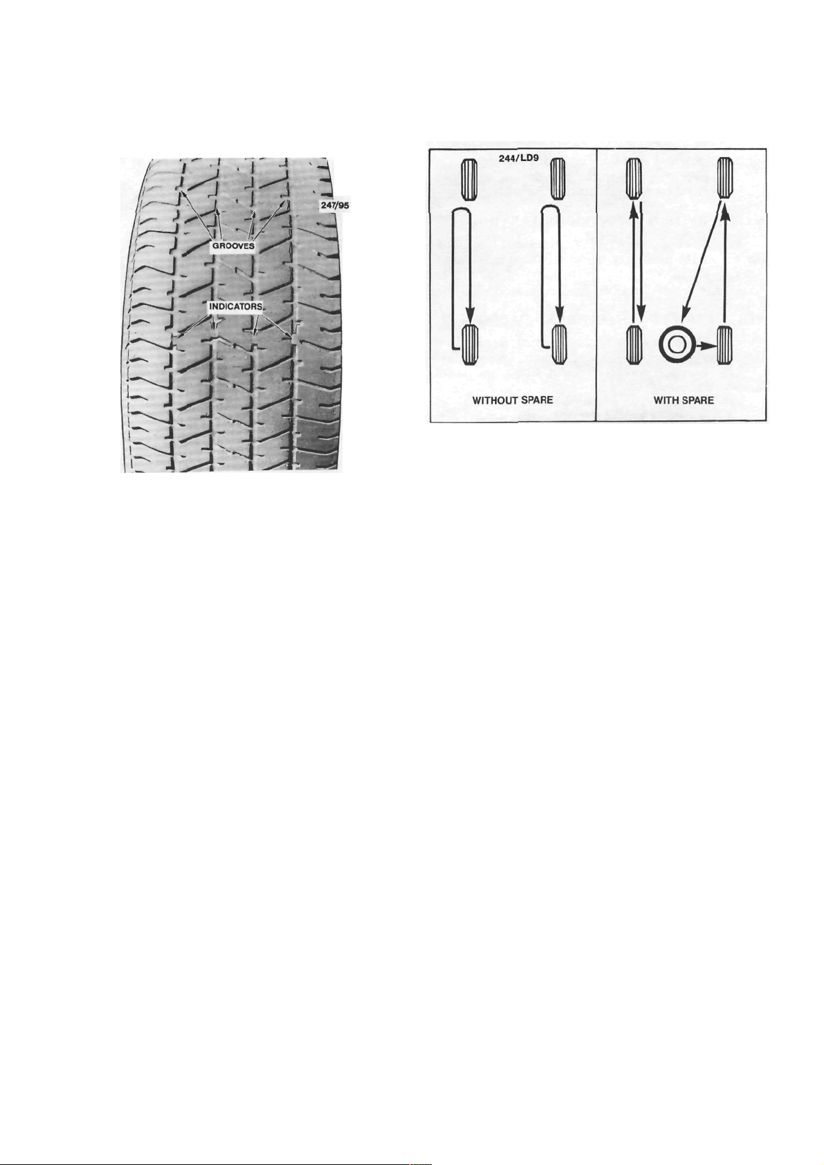
TYRES
The depth of the tire tread grooves should never
be allowed to be less than 1.5 mm before the tires are
renewed. The tires should also be renewed when any
damage, whether it be internal or external, is evident.
Minor punctures or leaks should be properly repaired.
Refer the tire to a tire specialist if there is any doubt
about the serviceability of the tire.
The tread, tread grooves and sidewalls should be
regularly inspected for foreign matter i.e. nails, stones
etc. Where foreign matter is detected it should be
removed from the tire and if necessary, the puncture
repaired.
The tire valves should always have the caps
installed, be regularly cleaned of dirt or dust and be
inspected for leakage and damage every time the tire
pressures are checked.
Regularly inspect the tread of the tires for signs of
uneven wear. If uneven wear is apparent, refer to the
heading Tire Wear Trouble Shooting in this section
for possible causes and cures. If the uneven tire wear
is noticed early enough, the cause correctly identified
and the necessary cure carried out, the life of the tire
should be extended.
24
Wheels and Tires
When the tire tread groove depth is less than 1.5
mm, or when the tire is worn to the point where the
tire wear indicators are level with the tread surface,
To preserve tire life it is good policy to periodically have the front wheels balanced and the front end
alignment checked on a reliable wheel alignment
machine.
The wheel and tire assemblies may be rotated at
20 000 km if desired. Rotation of the wheels and tires
will increase the period between tire renewal. Radial
tires should not be cross changed, they should be
changed from front to rear on the same side.
the tire should be renewed.
Tire rotation diagram. If desired, the wheel and tire
assemblies may be rotated every 20 000 km in the
manner shown. Vector SSS tire rotation not to include
spare wheel.
The air pressure in the tire is probably the single
most important aspect of tire care. Too little or too
much pressure in the tire can cause rapid wear or
complete failure through overheating. Where possible
the tire pressures should be checked and adjusted
when the tires are cold.
As a rule, different tire types, tread patterns or
sizes should never be used on the vehicle at one time.
All the tires on the vehicles, including the spare
should be a matched set to prevent the vehicle
behaving erratically under certain conditions. Under
no circumstances mix radial ply and conventional ply
tires.
25
ENGINE TUNE-UP
CAUTION: To prevent severe electrical shock, extreme care must be taken when
working on or near the electronic ignition system as dangerous high tension voltages
are produced in both the primary and secondary circuits. See the text for
precautionary notes.
1. TUNE-UP SPECIFICATIONS
Firing order................................................... 1 -3-4-2
Spark plugs:
Type .............................................NGK BPR 6ES
Gap ...........................................................1.1 mm
Tightening torque...................................... 20 Nm
Ignition timing with diagnostic link
connector jumped...........................10 deg BTDC
Idle speed (ECU controlled):
Manual transaxle 1.8 liter............ 850 ± 50 rpm
Manual transaxle 1.6 liter............ 800 ± 50 rpm
Automatic transaxle
(Park or Neutral).......................... 825 ± 50 rpm
Drive belt deflection:
Alternator ........................................... 14-16 mm
Power steering pump......................... 14-16 mm
Air conditioner compressor .................. 9-11 mm
NOTE: When performing an engine tuneup, a/ways compare the above Specifications
with the emission control information label
inside the engine compartment.
1.8 Liter Engine
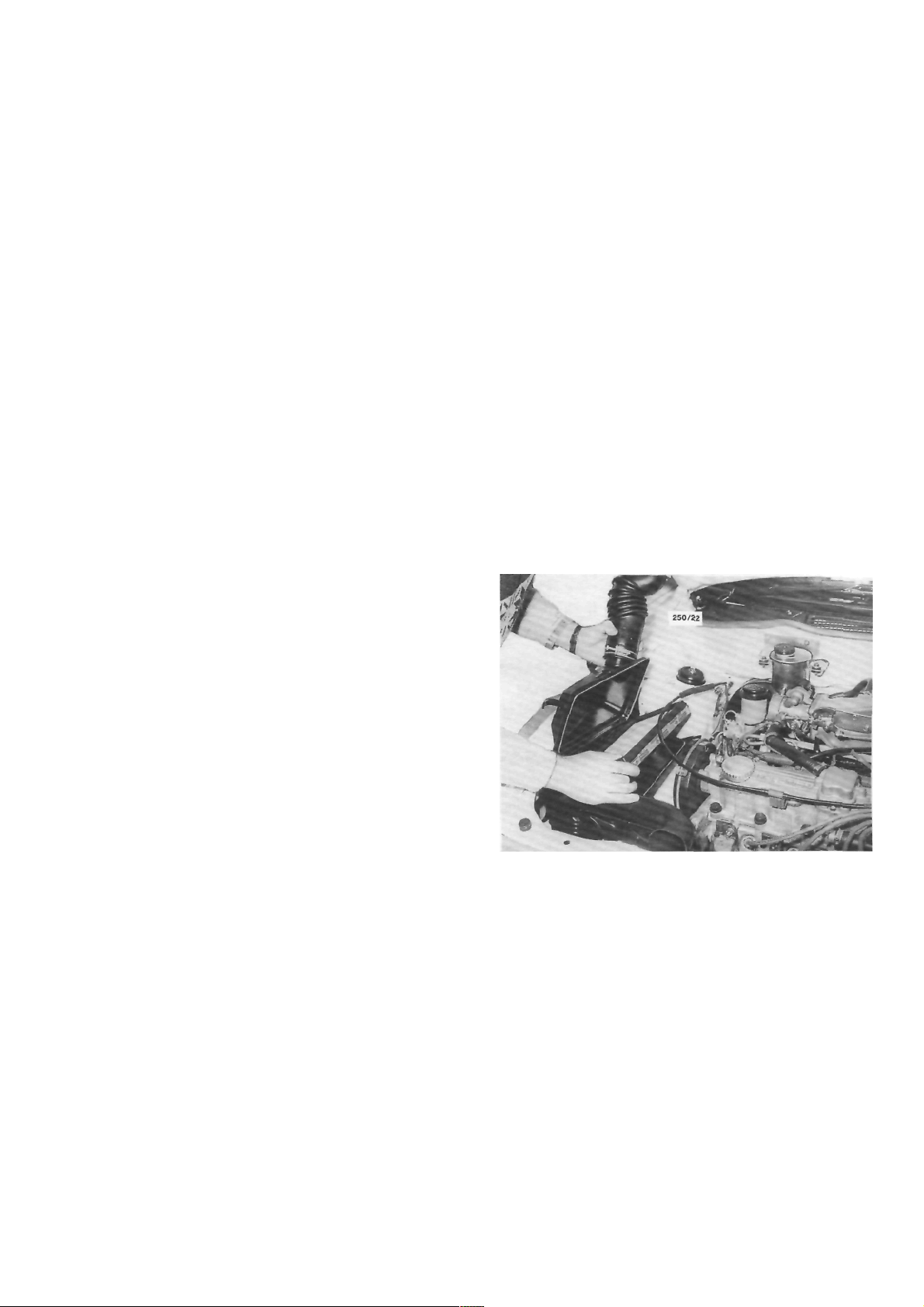
(1) Release the clamp securing the air intake
hose to the throttle body and disconnect the throttle
cable from the support bracket.
(2) Release the clips retaining the upper air
cleaner housing to the lower air cleaner housing and
raise the upper housing while disconnecting the air
intake hose from the throttle body. Remove the air
cleaner element.
2. TUNE-UP OPERATIONS
Special Equipment Required:
To Test Compression — Compression gauge
TO SERVICE AIR CLEANER
The air cleaner is equipped with a paper element.
The element should be regularly inspected but should
not be cleaned in service.
The element should be renewed every 40 000 km.
This distance is only a guide for normal operating
conditions and should be reduced accordingly if the
vehicle is operating under extremely dusty conditions.
NOTE: Paper air cleaner elements should
not be washed in petrol or any other type of
cleaning solvent. If the element has been
washed in solvent or has become oil soaked,
it should be discarded and a new element
installed.
The air cleaner element should be renewed at 40 000
km intervals. 1.8 liter engine.
(3) Clean the inside of the air cleaner housing
using a damp rag to remove all traces of dust and
check the upper housing and air inlet hose for cracks
and air leaks. Renew if necessary.
(4) Install a new air cleaner element to the lower
housing ensuring that the element is correctly seated
around the edges.
(5) Install the upper housing and lock the clips,
securing it to the lower housing. Connect the air
intake hose to the throttle body and the throttle cable
to the support bracket. Tighten the hose clamp
securely.
(6) Start the engine and check the air cleaner
assembly for air leaks.
26
Engine Tune-up
1.6 Liter Engine
(1) Remove the nuts and washers securing the
upper air cleaner housing to the lower air cleaner
housing and release the retaining clips.
(2) Remove the air cleaner element.
(3) Clean the inside of the air cleaner housing
using a damp rag to remove all traces of dust.
(4) Install a new air cleaner element ensuring that
the element is correctly seated around the edges.
(5) Install the upper housing and secure the
retaining clips. Tighten the retaining nuts securely.
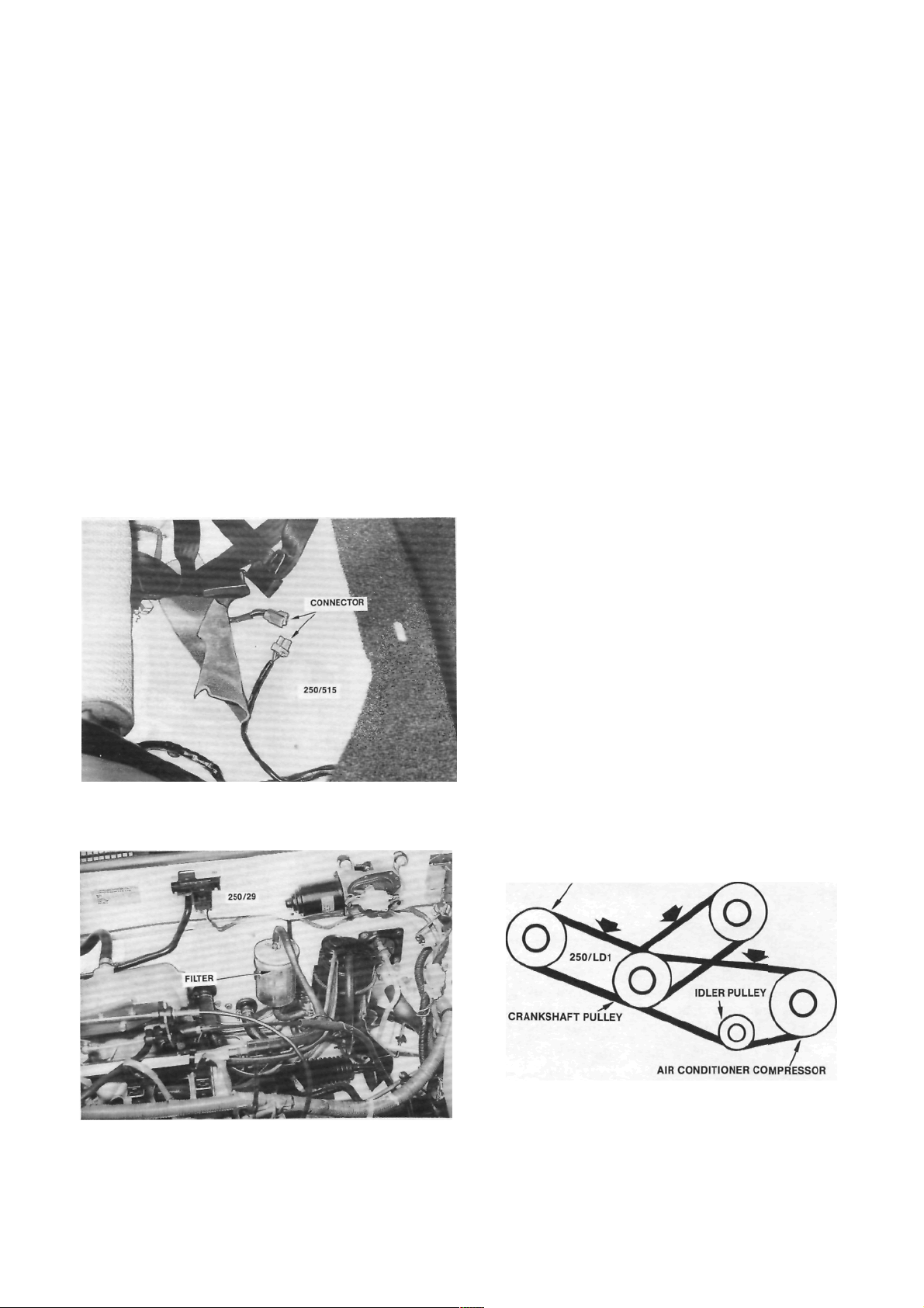
TO RENEW FUEL FILTER
filter should
The fuel
40 000 km.
be renewed every
(1) Depressurize the fuel system using the fol-
lowing procedure:
(a) Lift the front edge of the rear seat cushion
and remove the cushion from the vehicle.
When depressurizing the fuel system, remove the rear
seat cushion and disconnect the fuel pump wiring
connector.
(b) Disconnect the fuel pump wiring connector.
(c) Start and run the engine until it stalls.
Operate the starter motor for 10 seconds to ensure
that the fuel pressure has dissipated.
(2) Disconnect the negative battery terminal.
(3) Release the hose clamps and disconnect the
fuel hoses from the filter. Remove the filter from the
retaining clamp noting the direction of the arrow on
the filter body.
On some models it will be necessary to remove the
screw from the side of the clamp to allow the filler to
be removed.
Installation is a reversal of the removal procedure
with attention to the following points:
(1) Install the fuel filter with the arrow facing the
direction noted on removal, that is, in the direction of
fuel flow.
(2) Ensure that the hose clamps are tightened
securely.
(3) Connect the fuel pump wiring connector and
install the rear seat cushion.
(4) Start the engine and check for fuel leaks.
Rectify as necessary.
TO ADJUST DRIVE BELTS
It is essential that all drive belts are adjusted to
the correct tension to prevent slippage or premature
wear of the bearings in the alternator and, if equipped,
the power steering pump and air conditioner compressor.
(1) Push dow n on the d riv e bel t wit h a 10 kg
force midway between the pulleys of the drive belt
concerned.
On models with air conditioning, push down on
the upper section of the drive belt between the
compressor and crankshaft pulleys.
If the drive belt deflection is not within Specifications it will require adjustment as follows.
(2) Loosen the alternator and, if equipped, the
power steering pump pivot and adjusting bolts and
ALTERNATOR
POWER STEERING PUMP
Installed view of the fuel filter. Note the direction of the
arrow on the filter prior to removal.
Illustration of the alternator, power steering pump and
air conditioner compressor drive belts. The arrows
indicate the deflection measuring points.
Engine Tune-up
move the alternator or power steering pump as
required until the drive belt concerned has the
specified deflection.
On models with air conditioning, loosen the nut
in the centre of the idler pulley and turn the adjusting
bolt until the drive belt has the specified deflection.
(3) Tighten the alternator or power steering
pump bolts securely and check the belt tension.
On models with air conditioning, tighten the idler
pulley nut securely.
TO SERVICE SPARK PLUGS
The spark plugs should be renewed at intervals of
40 000 km.
Before removing the spark plugs ensure that the
area around each plug is clean to prevent foreign
matter entering the cylinder when the plugs are
removed.
Spark plugs removed from an engine in good
mechanical condition should have a light powdery
deposit ranging from light brown to grayish tan in
color. After considerable service the electrodes will
show signs of wear or normal burning. Spark plugs
showing a thick black oily deposit indicate an engine
in poor mechanical condition or possibly, that a plug
with too low a heat range has been installed.
Spark plugs showing a white or yellowish deposit
indicate sustained high speed driving or possibly that
plugs with too high a heat range have been installed,
particularly when these deposits are accompanied by
blistering of the porcelain and burning of the electrodes.
If the spark plugs are to be cleaned, use a
sandblasting machine and blow clean with compressed air. Ensure that all traces of abrasive grit are
removed from the spark plug threads and from the
well in the plug body. Carefully open the electrode gap
a little, by bending the side electrode, and lightly file
the electrodes flat with a points file.
27
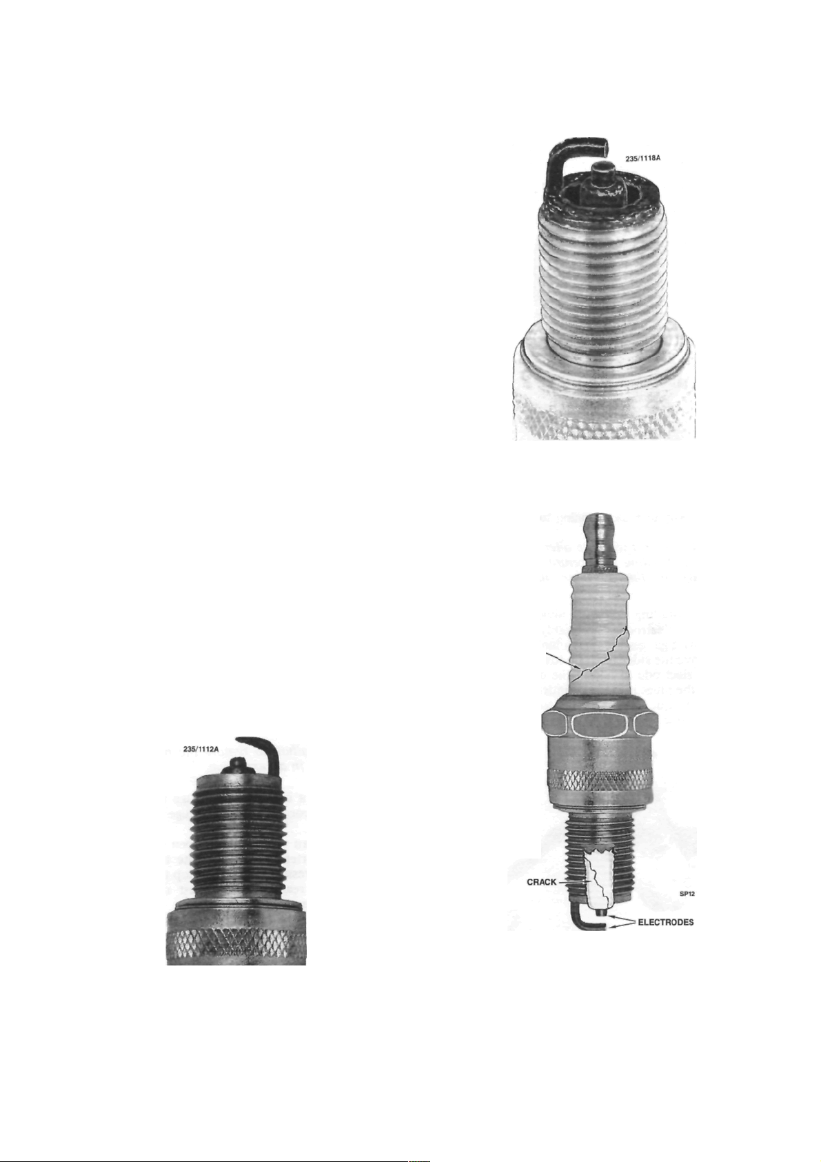
Black damp deposits can be caused by excessive oil
consumption or incorrect plug type. Spark plugs in this
condition are usually not firing.
CRACK
When plug electrodes are eroded to this degree the
spark can be considered worn out and should be
renewed using a plug of the recommended heat range
.
Cutaway view of spark plug showing a crack in the
insulator nose which can be caused by exerting pressure against the centre electrode when adjusting the
gap. The other crack shown on the insulator is caused
by tilting the plug spanner.
Engine Tune-up
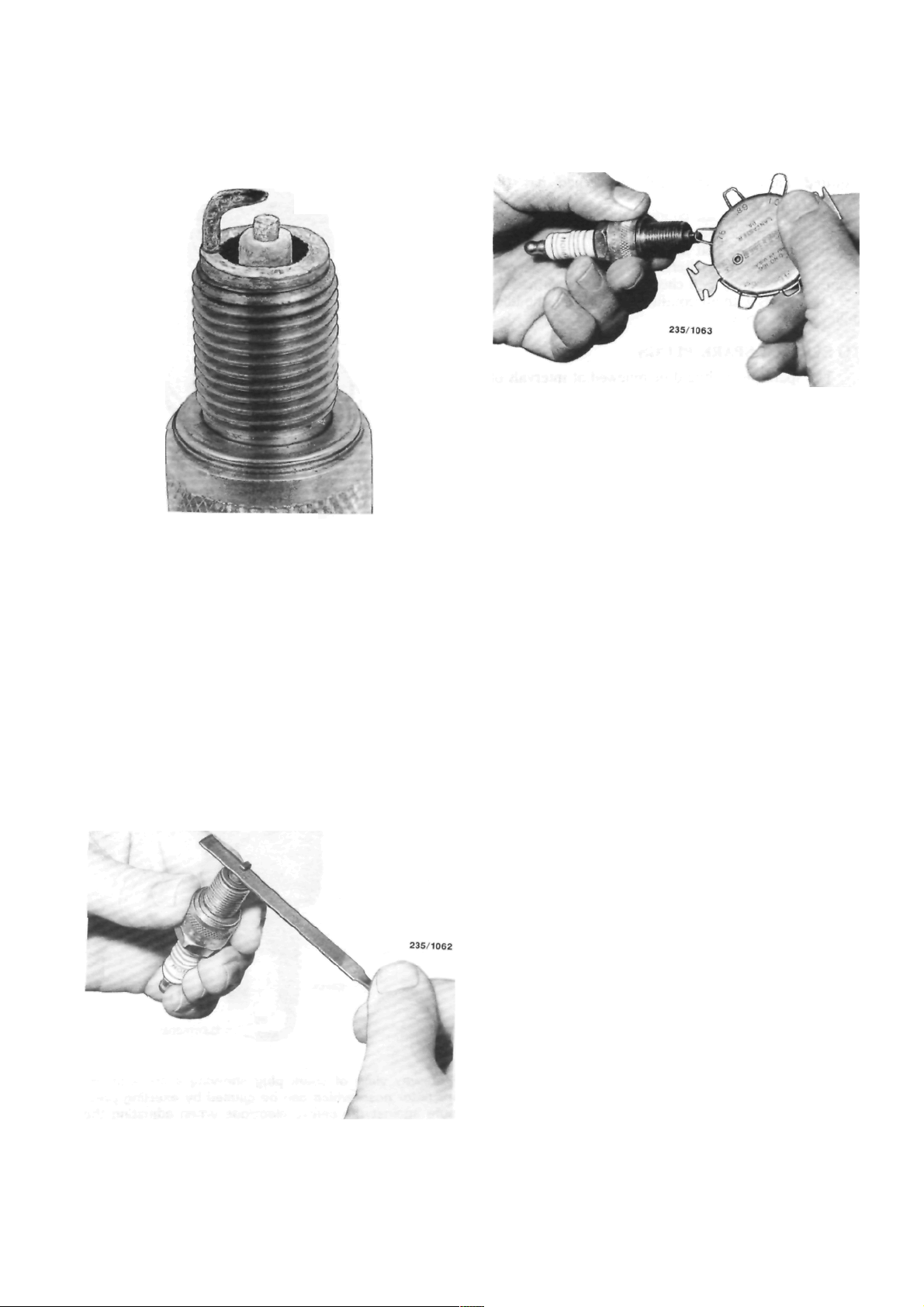
Spark plug with burnt electrodes and white blistered
appearance, possibly due to incorrect plug type, loose
plug or motor running too hot.
NOTE: Never attempt to alter the electrode
gap by bending the centre electrode as
damage to the porcelain insulator will
result.
Before installing any spark plugs measure the gap
between the electrodes, preferably with clean wire
gauges. If wire gauges are unavailable, use clean feeler
gauges. Move the side electrode towards or away from
the centre electrode to obtain the correct gap-
Screw the plugs into the cylinder head ringer tight,
then use a torque wrench to tighten the plugs lo the
specified torque.
Checking the spark plug electrode gap with a wire
gauge.
NOTE: If a torque wrench is unavailable,
extreme care must be taken when tightening
the spark plugs as over tightening may lead
to stripping of the thread from the cylinder
head. If the plugs are tightened with the
fingers and then taken up an additional 1/4
of a turn with a spark plug wrench, they will
be tight enough.
TO TEST COMPRESSION
(1) With the engine at operating temperature.
disconnect the high tension leads from the spark
plugs.
(2) Ensure that the area around each spark plug
is clean to prevent foreign matter entering the cylinders and remove the spark plugs.
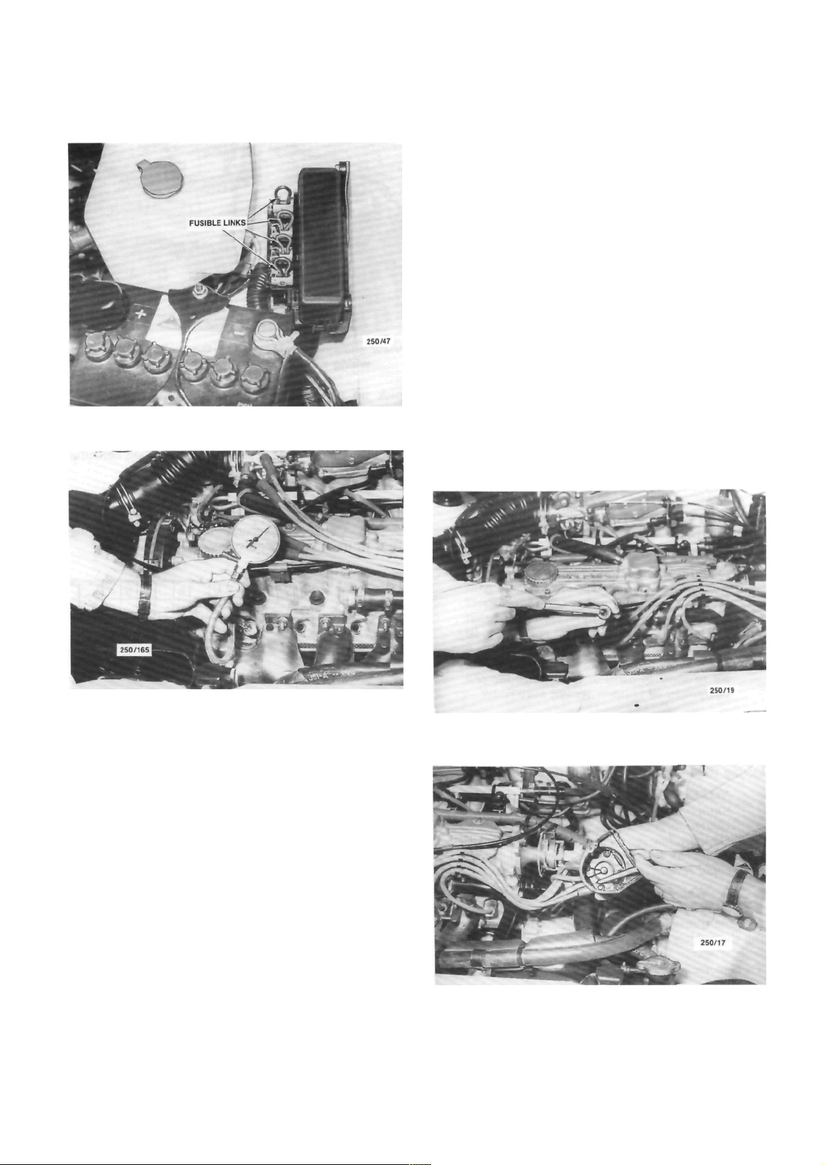
(3) Remove the fusible link that is positioned
third from the front of the fusible link connecting
block, located at the rear of the battery. Disconnect
the coil high tension lead from the coil.
NOTE: Failure to remove the fusible link
can result in an explosion.
Lightly file the plug electrodes flat with a points file
(4) Install a compression gauge to number one
spark hole according to the gauge manufacturers
instructions.
(5) Have an assistant fully open the throttle and
operate the starter switch to rotate the engine. Observe the compression gauge and stop the engine when
the gauge has reached the highest reading, usually
after 3 or 4 compression strokes.
(6) Record the reading and check the compres-
sion of the remaining cylinders in the same manner.
(7) Compare all the readings taken. Variation
between the highest and lowest reading cylinders
should not exceed 100 kPa.
(8) If a low reading is recorded on one or more
cylinders the trouble may be isolated as follows :
Engine Tune-up
29
View showing the location of the fusible links.
Refer to the Fuel and Engine Management section
for Specifications and Trouble Shooting.
NOTE: When working on or near electronic
ignition systems, care should be taken as
dangerous high voltages are present in both
the primary and secondary circuits.
The ignition switch should be turned off
before removing or installing any electrical
connections otherwise damage to the ignition system as well as severe electrical shock
could result.
TO SERVICE HIGH TENSION LEADS
Check the leads for perishing or cracking and
renew as required. Never attempt to repair defective
carbon impregnated core leads.
The lead may be carefully cleaned, using cloth
moistened with kerosene and then wiped completely
dry.
If an ohmmeter is available the electrical resis-
tance of the leads may be checked as follows:
Check the cylinder compressions using a compression
gauge.
(a) Inject a small amount of engine oil into the
spark plug hole of the cylinder concerned ensuring
that the oil is evenly distributed within the cylinder by
rotating the engine.
(b) Repeat the compression test on the cylinder
concerned.
A substantial increase of compression pressure
indicates faulty or worn piston rings, pistons or
cylinder.
No increase of compression pressure indicates
burnt, obstructed or sticking valves, or a leaking or
blown cylinder head gasket.
(9) Install the fusible link and connect the high
tension lead to the coil.
TO SERVICE THE DISTRIBUTOR
The electronic ignition system requires virtually
no maintenance except for checking of the distributor
cap. rotor and high tension leads as described below.
Check the spark plug high tension leads for cracks and
burnt or corroded terminals.
Check the distributor cap for cracks or tracking
between the terminals
.
30
Engine Tune-up
(1) With the distributor cap and leads removed
as an assembly, test one lead at a time, connecting the
meter probes at the spark plug end of the lead and at
the corresponding terminal inside the cap. Resistance
should be less than 15 000 ohms.
(2) If the resistance is more than 15 000 ohms
remove the lead from the distributor cap and check
(he resistance in the lead only. The lead should be
renewed if the resistance is still more than 15 000
ohms.
(3) High distributor cap resistance may be due
to corrosion deposits on the cap terminals. These
deposits should be removed with a small scraper or
emery cloth.
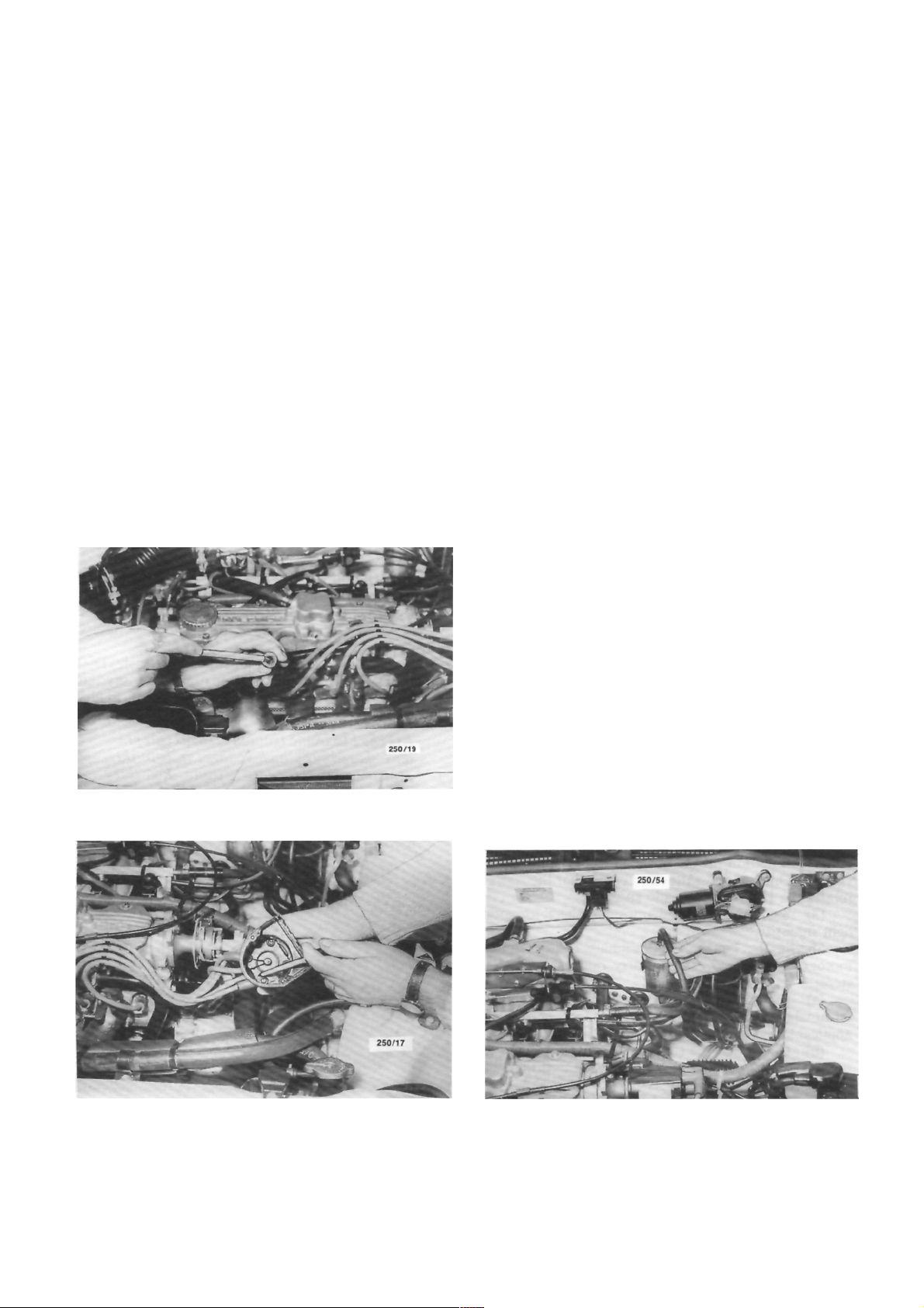
Check the distributor cap for cracks or tracking
between the high tension terminals on both the inside
and outside of the cap. Renew the cap if cracks or
tracking are evident.
Check the carbon brush in the centre of the
distributor cap for evidence of arcing and renew as
necessary.
Check the condition of the rotor and renew if
arced excessively or cracked.
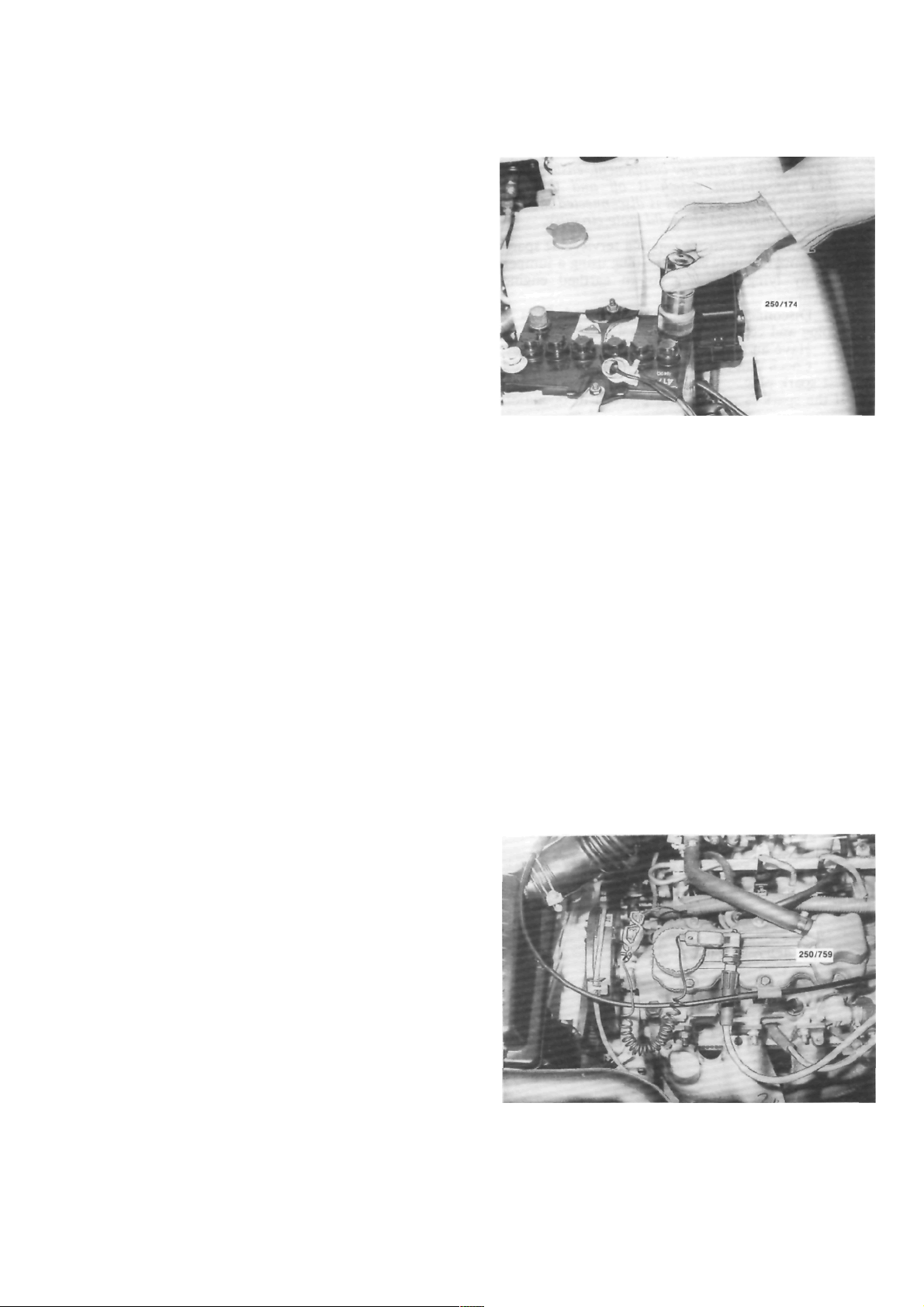
View showing the location of the tachometer pickup
wiring connector with the resistor installed
.
pick up wiring connector which is located on the
ignition coil wiring harness, and connect the positive
lead of an accurate tachometer to the brown wire
terminal in the wiring connector.
(3) Connect the negative lead to a good earthing
point.
HOW TO CONNECT ELECTRICAL TEST
EQUIPMENT
NOTE: Some types of tachometers, timing
lights and ignition system analysers are not
compatible with this type of electronic ignition system and may result in incorrect
readings. It is therefore recommended that
the manufacturer of the test equipment be
consulted before using the equipment.
Do not allow the tachometer lead connector to short to earth as damage to the test
equipment or ignition system may result.
Timing Light
(1) Connect the timing light to the engine fol-
lowing the instrument manufacturers instructions.
NOTE: Do not connect or disconnect the
timing light with the engine running as
voltage surges could damage the alternator.
Do not allow the high tension leads to open
circuit as damage to the ignition system
could result.
(2) Where necessary, connect the power leads of
the timing light to an external power source to prevent
possible transient voltages in the timing light damaging the vehicle alternator.
Tachometer
(1) Ensure that the tachometer is compatible
with the vehicle ignition system.
(2) Disconnect the resistor from the tachometer
TO CHECK AND ADJUST IGNITION TIMING
(1) Connect an accurate tachometer and timing
light to the engine as previously described.
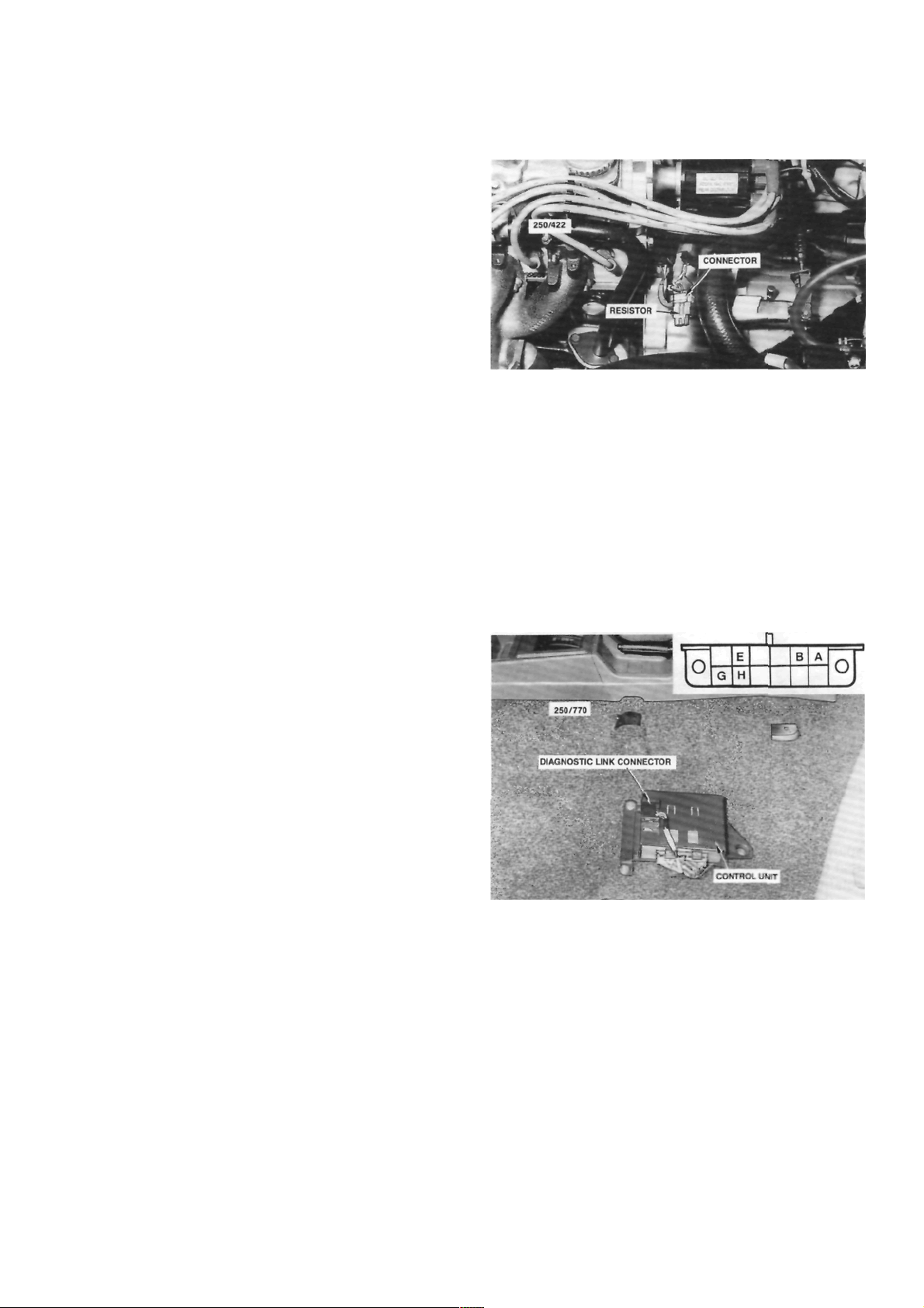
View showing the location of the diagnostic link
connector. Passengers seat removed for clarity.
Inset shows the diagnostic link connector terminal
identification.
(2) Start the engine and allow it to reach normal
operating temperature.
(3) Connect a jumper lead between terminals A
and B on the diagnostic link connector.
(4) With the engine idling at the specified speed,
check the ignition timing with the timing light.
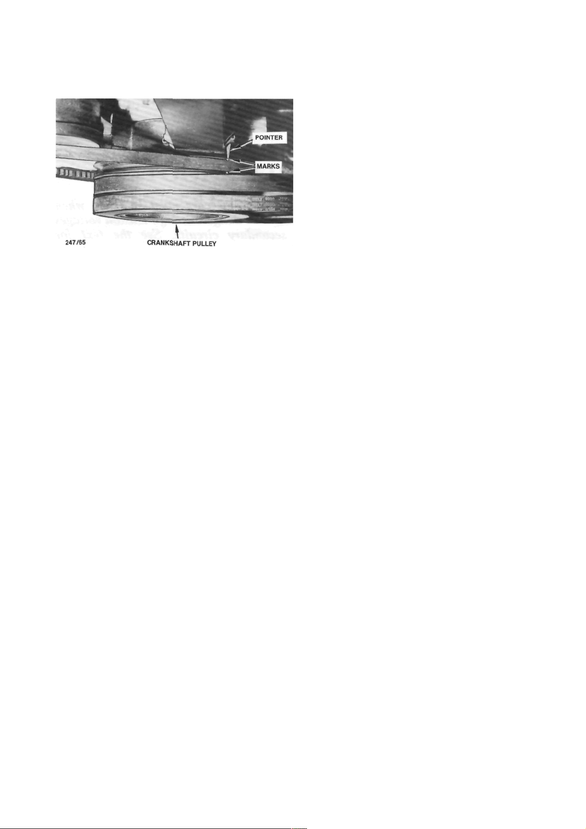
Correct timing exists when the marks on the
crankshaft pulley are aligned with the pointer on the
inner timing cover.
Engine Tune-up
(5) If adjustment is necessary, loosen the distrib-
utor body retaining nuts and turn the distributor body
until the correct setting is obtained.
(6) Tighten the distributor body retaining nuts
and ensure that the timing is sti ll correct.
(7) Remove the jumper lead from the diagnostic
link connector.
(8) Disconnect the timing light from the engine.
View of the engine timing marks showing the 10 deg
BTDC crankshaft notch aligned with the pointer on the
front of the engine.
TO ADJUST IDLE SPEED AND MIXTURE
The idle speed and mixture are not adjusted as
normal service procedure. However, should the performace of the vehicle indicate that the mixture is
incorrect, refer to the Fuel and Engine Management
section for the procedures to test for faulty components in the engine management system.

32
ROADSIDE TROUBLE SHOOTING
CAUTION: To prevent severe electrical shock extreme care must be taken when
working on or near the electronic ignition system as dangerous high tension voltages
are produced in both the primary and secondary circuits. See the text for
precautionary notes.
This section deals with the common causes of
engine failure to start, as inevitably there will come a
time when every driver will experience this problem
and will therefore need to call upon his own resources
to rectify the trouble. Roadside breakdowns other
than engine failure can be identified by reference to
the Trouble Shooting section on the particular component affected.
Trouble shooting is only a process of elimination
and provided the procedure is carried out correctly
and systematically an accurate diagnosis of the trouble
can be made in the minimum amount of time.
For an internal combustion engine to run there
are three basic requirements, these are ignition, fuel
and compression. There are other factors of course
but as a rule an engine's failure to start can be
attributed to a fault in one of these three systems.
Reports from field engineers of motoring organisations prove that the biggest percentage of engine
breakdowns are in the order of ignition or electrical
failure first, followed by fuel, with mechanical or
compression failure the least common.
Should the engine fail to start, first check that
there is adequate fuel in the tank and if so. carry out
the following checking procedures in the order described.
1. TROUBLE SHOOTING
jump starting, or being jump started by
another vehicle. If available use jumper
leads equipped with a surge protection device and follow the lead manufacturers instructions carefully, particularly regarding
the connection and disconnection of the
leads.
(1) Ensure that the booster battery is 12 volts
and the negative terminal is earthed.
(2) Ensure that the vehicles are not touching and
that the ignition and all accessories on both vehicles
are switched Off.
(3) Ensure that the transmissions on both vehi-
cles are in Park or Neutral and the handbrakes are
firmly applied.
(4) Remove the vent caps from the battery and
check the electrolyte level. Replenish with distilled
water as necessary.
TO JUMP START A VEHICLE
NOTE: Jump starting a vehicle can be
dangerous if the procedure described below
is not performed correctly. If any doubt
exists, it is recommended that the services of
a competent mechanic be obtained.
The vehicles covered by this manual are
equipped with complex electronic circuitry
which can be damaged by voltage surges.
These voltage surges can be generated when
View showing the correct jumper lead connections for
jump starting a vehicle. The leads shown are equipped
with a surge protection device.
Roadside Trouble Shooting
(5) Place the vent caps loosely over the cell
apertures.
(6) Con nect one end of the r ed ju mper lea d to
the positive ( + ) battery terminal of the booster
battery and the other end of the red lead to the
positive (+) battery terminal of the discharged battery.
NOTE: The battery emits hydrogen gas
which is explosive. Do not expose the battery
to naked /lames or sparks.
Do not lean over the battery when con-
necting the jumper leads.
Do not allow the ends of the jumper leads
to touch one another or any part of the
engine.
(7) Connect one end of the black juniper lead to
the negative (-) battery terminal of the booster
battery and the other end of the black lead to a good
earthing point on the engine of the vehicle with the
discharged battery.
NOTE: Do not connect the jumper lead
directly to the negative (-) battery terminal
of the discharged battery.
(8) Start the engine on the vehicle with the
booster battery and run the engine at a moderate
speed.
(9) Start the engine on the vehicle with the
discharged battery.
(10) If possible, leave the engines of both vehi-
cles running for 10 minutes.
(11) Disconnect the jumper leads in the reverse
order of the sequence in which they were connected.
2. TO CHECK IGNITION AND ELECTRICAL
SYSTEM
Ensure that the battery posts and terminals are clean.
(d) Where necessary carry out repairs to (b) and
(c).
Repeat the check procedure. Should the starter
motor still not operate, or the lamps not illuminate,
one or more of the following faults may be the cause:
No starter motor operation or lamps: Battery flat
or defective.
Lamps illuminate but no starter operation: Starter
motor drive jammed in mesh with flywheel ring gear.
Starter motor or solenoid defective. Ignition/starter
switch faulty. On automatic transaxle models, faulty
neutral safety switch.
Lamps dim and starter operation sluggish: Dis-
charged battery or fault in starter motor. Battery flat
due to broken fan belt or defective alternator. Faulty
battery due to cell breakdown.
NOTE: Electronic ignition systems can produce dangerously high voltages in both the
primary and secondary circuits. For this
reason, extreme care must be taken when
performing these checks. When disconnect-
(1) Switch on the ignition and check for warning
lamp illumination on the dashboard.
(2) Operate the starter and check that the starter
rotates the engine at a steady speed.
(3) Switch on the headlamps and check for good
light intensity.
Should the lamps not illuminate or the starter
motor not turn the engine, carry out the following
steps:
(a) Remove the battery terminals and clean both
terminals and posts. Connect the terminals and where
applicable tighten firmly but not excessively.
(b) Check that the earth lead from the battery to
the engine or body frame is not broken and that the
connections are clean and secure.
. (c) Check that the lead from the battery to the
starter motor or starter solenoid is intact and has a
clean and secure connection.
Securely earth the body of a test spark plug to check
for sparks at the spark plug leads.
Roadside Trouble Shooting
ing the wiring from any component, ensure
that the ignition switch is off and the
negative battery terminal is disconnected to
prevent damage to the solid state circuitry.
(4) Open the electrode gap of a serviceable spark
plug to 6 mm. Securely earth the plug using a jumper
lead or by tying the plug to an earthed engine
component.
(5) Disconnect the high tension lead from a
spark plug and connect it to the test spark plug.
(6) Have an assistant operate the starter motor.
(7) Check that a spark, if any, jumps the gap on
the test spark plug.
If the spark is satisfactory, proceed to operation
(8).
If there is no spark, proceed as follows:
(a) Check the high tension leads to ensure that
they are dry and that the insulation is not cracked or
perished. Check the ends of the leads for burning.
Using an ohmmeter, measure the resistance in
each high tension lead. The resistance should be no
more than 15 000 ohms per lead.
Check the spark plug high tension leads for cracks and
burnt or corroded terminals.
(b) Check the distributor cap to ensure that it is
dry and clean. Examine both the inside and outside of
the cap for cracks or tracking, particularly between the
high tension lead segments.
Check that the carbon brush in the centre of the
distributor cap interior face is clean and dry and
ensure that the brush moves freely in and out of its
locating hole.
(c) Check the rotor arm for cracks, deposits and
burning on the metal arm.
(d) Ensure that the high tension leads have dry.
clean and secure connections on the distributor cap.
(8) If the above checks result in a good spark at
the spark plug high tension leads but the engine is still
not operating satisfactorily, remove all the spark plugs
and check the condition and electrode gap as described in the Engine Tune-up section under the
appropriate heading.
3. TO CHECK FUEL SYSTEM
Due to the complex nature of the EFI system, it is
recommended that should the following checks prove
satisfactory but the engine fail to start, reference be
made to the Fuel and Engine Management section of
this manual or a Nissan workshop be consulted.
(1) Check that the fuel tank contains a reasonable amount of fuel.
(2) Have an assistant switch the ignition on and
off while squeezing the fuel supply hose with the
fingers. If the fuel pump is operating it should be
possible to feel the fuel pressure increase for approximately two seconds.
NOTE: When conducting the above test it
should be possible to hear the fuel pump and
ignition relays clicking when the ignition is
switched on and off
If the fuel pump relay fails, power will be
supplied to the fuel pump via the oil pressure
Check the distributor cap for cracks or tracking
between the terminals.
Squeeze the fuel supply hose while the ignition is
switched On. An increase in pressure should be felt
.
Roadside Trouble Shooting
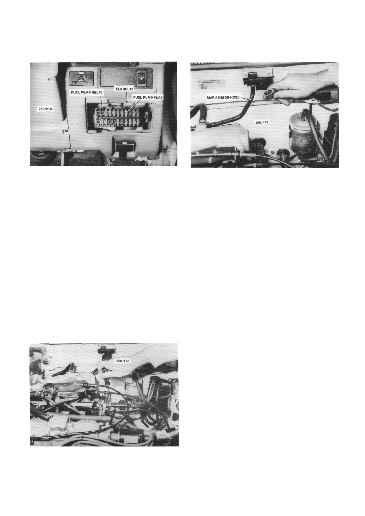
View showing the location of the fuel pump fuse and
the EGI and fuel pump relays.
switch. When starting the engine, the fuel
pump will not operate until the oil pressure
is sufficient to extinguish the oil pressure
warning lamp. Therefore it will be necessary
to operate the starter motor for a longer
period than usual to start the engine.
(3) If the fuel pump can not be fe lt operating,
check the fuel pump fuse located in the fuse panel
adjacent to the steering column.
If the fuel pump fuse is serviceable, refer to the
Fuel and Engine Management section for detailed
tests on the fuel pump.
(4) Check that all fuel hose connections are
secure.
(5) Remove the spark plugs and check for petrol
saturation of the electrodes which indicates flooding.
Thoroughly clean and dry the spark plugs before
replacement.
Fully depress the throttle pedal and turn the
ignition switch to the start position. If the engine does
not start, proceed as follows.
Ensure that all fuel connections are securely tightened.
35
Check that the MAP sensor hose is not blocked or split
and ensure that all electrical connections are clean and
secure.
If flooding persists, refer to the Fuel and Engine
Management section.
(6) Check that all EFI electrical wiring connec-
tors are clean and secure.
(7) Check that the MAP sensor vacuum hose is
securely connected at each end and is not split or
blocked.
4. TO CHECK MECHANICAL SYSTEM
The following check procedure assumes that the
starter motor will rotate the engine. If not, on manual
transaxle models, depress the clutch pedal to disengage the engine from the transaxle in case the fault lies
within the transaxle.
If the starter motor will not rotate the engine, it
will be necessary to remove the starter motor and
attempt to turn the engine over manually. This will
establish whether the fault lies with the starter motor,
which could be jammed or defective, or with the
engine, which could be seized or have broken internal
components such as connecting rods, pistons and
crankshafts etc.
If the starter motor is not at fault and the engine
will not rotate manually, refer to the Engine Mechanical Trouble Shooting heading in the Engine section.
It should be noted that the only way that cylinder
compression can be accurately tested is with a compression gauge. The method described in the following
procedure is only intended to give a rough indication
when checking for causes of engine breakdown,
(I) When the engine is cool, check for loss of
coolant from the cooling system.
If coolant loss is evident, check carefully for any
indication of external leakage. Remove the engine oil
dipstick and check for water contamination (emulsification) of the oil. When oil mixes with water it will
Loading...