


 Loading...
C TRANSMISSION/TRANSAXLE
SECTION
AUTOMATIC TRANSAXLE
CONTENTS
A
B
AT
D
E
INDEX FOR DTC ....................................................... |
5 |
Alphabetical Index ................................................... |
5 |
DTC No. Index ........................................................ |
6 |
PRECAUTIONS ......................................................... |
7 |
Precautions for Supplemental Restraint System |
|
(SRS) “AIR BAG” and “SEAT BELT PRE-TEN- |
|
SIONER” ................................................................. |
7 |
PrecautionsforOnBoardDiagnostic(OBD)System |
|
of A/T and Engine ................................................... |
7 |
PrecautionsforA/TAssemblyorTCMReplacement..... |
8 |
Precautions ............................................................. |
9 |
Service Notice or Precautions ................................ |
11 |
Wiring Diagrams and Trouble Diagnosis ................ |
11 |
PREPARATION ........................................................ |
12 |
Special Service Tools ............................................ |
12 |
Commercial Service Tools ..................................... |
14 |
A/T FLUID ................................................................ |
15 |
Changing A/T Fluid ............................................... |
15 |
Checking A/T Fluid ................................................ |
15 |
A/T CONTROL SYSTEM ......................................... |
16 |
Cross-Sectional View ............................................ |
16 |
Shift Mechanism .................................................... |
17 |
TCM Function ........................................................ |
34 |
Input/Output Signal of TCM ................................... |
35 |
CAN Communication ............................................. |
35 |
Line Pressure Control ........................................... |
36 |
Shift Control .......................................................... |
36 |
Lock-Up Control .................................................... |
38 |
ON BOARD DIAGNOSTIC (OBD) SYSTEM ........... |
40 |
Introduction ........................................................... |
40 |
OBD-II Function for A/T System ............................ |
40 |
One or Two Trip Detection Logic of OBD-II ........... |
40 |
OBD-II Diagnostic Trouble Code (DTC) ................ |
40 |
Malfunction Indicator Lamp (MIL) .......................... |
43 |
TROUBLE DIAGNOSIS ........................................... |
44 |
DTC Inspection Priority Chart ............................... |
44 |
Fail-Safe ................................................................ |
44 |
How To Perform Trouble Diagnosis For Quick and |
|
Accurate Repair .................................................... |
47 |
A/T Electrical Parts Location ................................. |
52 |
Circuit Diagram ...................................................... |
53 |
Inspections Before Trouble Diagnosis ................... |
54 |
Check Before Engine is Started ............................. |
58 |
Check at Idle ........................................................... |
58 |
Cruise Test - Part 1 ................................................ |
60 |
Cruise Test - Part 2 ................................................ |
61 |
Cruise Test - Part 3 ................................................ |
62 |
Shift Schedule ....................................................... |
63 |
Symptom Chart ....................................................... |
64 |
TCM Input/Output Signal Reference Values .......... |
71 |
CONSULT-II Function (TCM) ................................. |
74 |
Diagnostic Procedure Without CONSULT-II .......... |
80 |
DTC U1000 CAN COMMUNICATION LINE ............. |
83 |
Description ............................................................. |
83 |
On Board Diagnosis Logic ..................................... |
83 |
Possible Cause ...................................................... |
83 |
DTC Confirmation Procedure ................................ |
83 |
Wiring Diagram — AT — CAN ............................. |
... 84 |
Diagnostic Procedure ............................................ |
85 |
DTC P0500 VEHICLE SPEED SENSOR MTR ........ |
86 |
Description ............................................................. |
86 |
On Board Diagnosis Logic ..................................... |
86 |
Possible Cause ...................................................... |
86 |
DTC Confirmation Procedure ................................ |
86 |
Diagnostic Procedure ............................................ |
87 |
DTC P0613 TCM PROCESSOR .............................. |
88 |
Description ............................................................. |
88 |
On Board Diagnosis Logic ..................................... |
88 |
Possible Cause ...................................................... |
88 |
DTC Confirmation Procedure ................................ |
88 |
Diagnostic Procedure ............................................ |
89 |
DTC P0705 PARK/NEUTRAL POSITION SWITCH... 90 |
|
Description ............................................................. |
90 |
On Board Diagnosis Logic ..................................... |
90 |
Possible Cause ...................................................... |
90 |
DTC Confirmation Procedure ................................ |
90 |
Wiring Diagram — AT — PNP/SW ...................... |
... 91 |
Diagnostic Procedure ............................................ |
92 |
Component Inspection ........................................... |
94 |
DTC P0710 A/T FLUID TEMPERATURE SENSOR |
|
F
G
H
I
J
K
L
M
Revision: July 2005 |
AT-1 |
2005 Maxima |

CIRCUIT ................................................................... |
95 |
Description ............................................................. |
95 |
On Board Diagnosis Logic ..................................... |
95 |
Possible Cause ...................................................... |
95 |
DTC Confirmation Procedure ................................ |
95 |
Wiring Diagram — AT — FTS .............................. |
... 96 |
Diagnostic Procedure ............................................ |
97 |
Component Inspection ........................................... |
99 |
DTC P0711 FLUID TEMPERATURE SENSOR PER- |
|
FORMANCE ........................................................... |
100 |
Description ........................................................... |
100 |
On Board Diagnosis Logic ................................... |
100 |
Possible Cause .................................................... |
100 |
DTC Confirmation Procedure .............................. |
100 |
Wiring Diagram — AT — FTSP ........................... |
. 101 |
Diagnostic Procedure .......................................... |
102 |
Component Inspection ......................................... |
104 |
DTCP0717TURBINEREVOLUTIONSENSORCIR- |
|
CUIT ....................................................................... |
105 |
Description ........................................................... |
105 |
On Board Diagnosis Logic ................................... |
105 |
Possible Cause .................................................... |
105 |
DTC Confirmation Procedure .............................. |
105 |
Wiring Diagram — AT — TRSC ........................... |
. 106 |
Diagnostic Procedure .......................................... |
107 |
Component Inspection ......................................... |
108 |
DTC P0722 VEHICLE SPEED SENSOR A/T (REV- |
|
OLUTION SENSOR) CIRCUIT ............................... |
109 |
Description ........................................................... |
109 |
On Board Diagnosis Logic ................................... |
109 |
Possible Cause .................................................... |
109 |
DTC Confirmation Procedure .............................. |
109 |
Wiring Diagram — AT — VSSATC ...................... |
. 110 |
Diagnostic Procedure ........................................... |
111 |
Component Inspection ......................................... |
112 |
DTC P0726 ENGINE SPEED INPUT CIRCUIT PER- |
|
FORMANCE ........................................................... |
113 |
Description ........................................................... |
113 |
On Board Diagnosis Logic ................................... |
113 |
Possible Cause .................................................... |
113 |
DTC Confirmation Procedure .............................. |
113 |
Diagnostic Procedure .......................................... |
113 |
DTC P0731 A/T 1ST GEAR FUNCTION ................ |
115 |
Description ........................................................... |
115 |
On Board Diagnosis Logic ................................... |
115 |
Possible Cause .................................................... |
115 |
DTC Confirmation Procedure .............................. |
115 |
Wiring Diagram — AT — 1STSIG ........................ |
. 116 |
Diagnostic Procedure .......................................... |
117 |
DTC P0732 A/T 2ND GEAR FUNCTION ............... |
118 |
Description ........................................................... |
118 |
On Board Diagnosis Logic ................................... |
118 |
Possible Cause .................................................... |
118 |
DTC Confirmation Procedure .............................. |
118 |
Wiring Diagram — AT — 2NDSIG ....................... |
. 120 |
Diagnostic Procedure .......................................... |
122 |
DTC P0733 A/T 3RD GEAR FUNCTION ............... |
124 |
Description ........................................................... |
124 |
On Board Diagnosis Logic ................................... |
124 |
Possible Cause .................................................... |
124 |
DTC Confirmation Procedure ............................... |
124 |
Wiring Diagram — AT — 3RDSIG ....................... |
.126 |
Diagnostic Procedure ........................................... |
128 |
DTC P0734 A/T 4TH GEAR FUNCTION ................ |
130 |
Description ........................................................... |
130 |
On Board Diagnosis Logic ................................... |
130 |
Possible Cause .................................................... |
130 |
DTC Confirmation Procedure ............................... |
130 |
Wiring Diagram — AT — 4THSIG ........................ |
.132 |
Diagnostic Procedure ........................................... |
133 |
DTC P0735 A/T 5TH GEAR FUNCTION ................ |
135 |
Description ........................................................... |
135 |
On Board Diagnosis Logic ................................... |
135 |
Possible Cause .................................................... |
135 |
DTC Confirmation Procedure ............................... |
135 |
Wiring Diagram — AT — 5THSIG ........................ |
.137 |
Diagnostic Procedure ........................................... |
139 |
DTC P0744 A/T TCC S/V FUNCTION (LOCK-UP) .141 |
|
Description ........................................................... |
141 |
On Board Diagnosis Logic ................................... |
141 |
Possible Cause .................................................... |
141 |
DTC Confirmation Procedure ............................... |
141 |
Wiring Diagram — AT — TCCSIG ....................... |
.142 |
Diagnostic Procedure ........................................... |
143 |
DTC P0745 PRESSURE CONTROL SOLENOID |
|
VALVE A (LINE PRESSURE) ................................. |
144 |
Description ........................................................... |
144 |
On Board Diagnosis Logic ................................... |
144 |
Possible Cause .................................................... |
144 |
DTC Confirmation Procedure ............................... |
144 |
Wiring Diagram — AT — PC/A ............................ |
.145 |
Diagnostic Procedure ........................................... |
146 |
Component Inspection ......................................... |
148 |
DTC P0750 SHIFT SOLENOID VALVE A .............. |
149 |
Description ........................................................... |
149 |
On Board Diagnosis Logic ................................... |
149 |
Possible Cause .................................................... |
149 |
DTC Confirmation Procedure ............................... |
149 |
Wiring Diagram — AT — SSV/A .......................... |
.150 |
Diagnostic Procedure ........................................... |
151 |
Component Inspection ......................................... |
153 |
DTC P0755 SHIFT SOLENOID VALVE B .............. |
154 |
Description ........................................................... |
154 |
On Board Diagnosis Logic ................................... |
154 |
Possible Cause .................................................... |
154 |
DTC Confirmation Procedure ............................... |
154 |
Wiring Diagram — AT — SSV/B .......................... |
.155 |
Diagnostic Procedure ........................................... |
156 |
Component Inspection ......................................... |
158 |
DTC P0760 SHIFT SOLENOID VALVE C .............. |
159 |
Description ........................................................... |
159 |
On Board Diagnosis Logic ................................... |
159 |
Possible Cause .................................................... |
159 |
DTC Confirmation Procedure ............................... |
159 |
Wiring Diagram — AT — SSV/C .......................... |
.160 |
Diagnostic Procedure ........................................... |
161 |
Component Inspection ......................................... |
163 |
DTCP0762SHIFTSOLENOIDVALVECSTUCKON.164 |
|
Revision: July 2005 |
AT-2 |
2005 Maxima |

Description .......................................................... |
164 |
On Board Diagnosis Logic .................................. |
164 |
Possible Cause ................................................... |
164 |
DTC Confirmation Procedure .............................. |
164 |
Wiring Diagram — AT — SSV/CS ....................... |
. 165 |
Diagnostic Procedure .......................................... |
166 |
Component Inspection ........................................ |
168 |
DTC P0765 SHIFT SOLENOID VALVE D ............. |
169 |
Description .......................................................... |
169 |
On Board Diagnosis Logic .................................. |
169 |
Possible Cause ................................................... |
169 |
DTC Confirmation Procedure .............................. |
169 |
Wiring Diagram — AT — SSV/D ......................... |
. 170 |
Diagnostic Procedure .......................................... |
171 |
Component Inspection ........................................ |
173 |
DTC P0770 SHIFT SOLENOID VALVE E ............. |
174 |
Description .......................................................... |
174 |
On Board Diagnosis Logic .................................. |
174 |
Possible Cause ................................................... |
174 |
DTC Confirmation Procedure .............................. |
174 |
Wiring Diagram — AT — SSV/E ......................... |
. 175 |
Diagnostic Procedure .......................................... |
176 |
Component Inspection ........................................ |
178 |
DTC P0775 PRESSURE CONTROL SOLENOID |
|
VALVE B (SHIFT PRESSURE) .............................. |
179 |
Description .......................................................... |
179 |
On Board Diagnosis Logic .................................. |
179 |
Possible Cause ................................................... |
179 |
DTC Confirmation Procedure .............................. |
179 |
Wiring Diagram — AT — PC/B ............................ |
. 180 |
Diagnostic Procedure .......................................... |
181 |
Component Inspection ........................................ |
183 |
DTC P0780 SHIFT ................................................. |
184 |
Description .......................................................... |
184 |
On Board Diagnosis Logic .................................. |
184 |
Possible Cause ................................................... |
184 |
DTC Confirmation Procedure .............................. |
184 |
Wiring Diagram — AT — SFTFNC ...................... |
. 185 |
Diagnostic Procedure .......................................... |
187 |
DTC P0795 PRESSURE CONTROL SOLENOID |
|
VALVE C (TCC AND SHIFT PRESSURE) ............ |
188 |
Description .......................................................... |
188 |
On Board Diagnosis Logic .................................. |
188 |
Possible Cause ................................................... |
188 |
DTC Confirmation Procedure .............................. |
188 |
Wiring Diagram — AT — PC/C ........................... |
. 189 |
Diagnostic Procedure .......................................... |
190 |
Component Inspection ........................................ |
192 |
DTC P0797 PRESSURE CONTROL SOLENOID |
|
VALVE C STUCK ON ............................................ |
193 |
Description .......................................................... |
193 |
On Board Diagnosis Logic .................................. |
193 |
Possible Cause ................................................... |
193 |
DTC Confirmation Procedure .............................. |
193 |
Wiring Diagram — AT — PC/CS ......................... |
. 194 |
Diagnostic Procedure .......................................... |
195 |
Component Inspection ........................................ |
197 |
DTC P0826 MANUAL MODE SWITCH CIRCUIT . 198 |
|
Description .......................................................... |
198 |
CONSULT-IIReferenceValueinDataMonitorMode |
|||
|
|
|
. 198 |
On Board Diagnosis Logic ................................... |
|
198 |
|
Possible Cause .................................................... |
|
|
198 |
DTC Confirmation Procedure .............................. |
|
198 |
|
Wiring Diagram — AT — MMSW |
........................ |
. 199 |
|
Diagnostic Procedure .......................................... |
|
|
201 |
Component Inspection ......................................... |
|
|
203 |
Position Indicator ................................................. |
|
|
203 |
DTC P0882 TCM POWER INPUT SIGNAL ........... |
204 |
||
Description ........................................................... |
|
|
204 |
On Board Diagnosis Logic ................................... |
|
204 |
|
Possible Cause .................................................... |
|
|
204 |
DTC Confirmation Procedure .............................. |
|
204 |
|
Wiring Diagram — AT — PWR/IN |
....................... |
. 205 |
|
Diagnostic Procedure .......................................... |
|
|
207 |
Component Inspection ......................................... |
|
|
208 |
DTC P1726 ELECTRIC THROTTLE CONTROL |
|
||
SYSTEM ................................................................. |
|
|
209 |
Description ........................................................... |
|
|
209 |
TROUBLE DIAGNOSIS FOR SYMPTOMS ........... |
210 |
||
A/T CHECK Indicator Lamp does not come on ... |
210 |
||
Engine Cannot Be Started In “P” or “N” Position.212. |
|||
In “P” Position, Vehicle Moves When Pushed .. |
...212 |
||
In “N” Position, Vehicle Moves |
.......................... |
...213 |
|
Large Shock (“N” to “D” Position) ........................ |
214 |
||
Vehicle Does Not Creep Backward In “R” Position.215 |
|||
Vehicle Does Not Creep Forward In “D” Position . 216 |
|||
Vehicle Cannot Be Started From D1 .................... |
217 |
||
A/T Does Not Shift: D1 → |
D2 ............................... |
|
217 |
A/T Does Not Shift: D2 → |
D3 ............................... |
|
218 |
A/T Does Not Shift: D3 → |
D4 ............................... |
|
219 |
A/T Does Not Shift: D4 → |
D5 ............................... |
|
220 |
A/T Does Not Perform Lock-up |
........................... |
221 |
|
A/T Does Not Hold Lock-up Condition ................. |
222 |
||
Lock-up Is Not Released ..................................... |
|
|
223 |
Cannot Be Changed to Manual Mode ................. |
224 |
||
A/T Does Not Shift: 5th gear → |
4th gear ............. |
225 |
|
A/T Does Not Shift: 4th gear → |
3rd gear ............. |
226 |
|
A/T Does Not Shift: 3rd gear → |
2nd gear ............ |
226 |
|
A/T Does Not Shift: 2nd gear → |
1st gear ............ |
227 |
|
Vehicle Does Not Decelerate By Engine Brake ... |
228 |
||
TCM Self-diagnosis Does Not Activate ............... |
229 |
||
SHIFT CONTROL SYSTEM ................................... |
|
231 |
|
Control Device ..................................................... |
|
|
231 |
Control Cable ....................................................... |
|
|
232 |
A/T SHIFT LOCK SYSTEM |
................................... |
|
233 |
Description ........................................................... |
|
|
233 |
Shift Lock System Electrical Parts Location ........ |
233 |
||
Wiring Diagram — AT — SHIFT .......................... |
|
. 234 |
|
Shift Lock Control Unit Reference Values ........... |
235 |
||
Component Inspection ......................................... |
|
|
236 |
ON-VEHICLE SERVICE ......................................... |
|
|
238 |
Revolution Sensor Replacement ......................... |
238 |
||
Turbine Revolution Sensor Replacement ............ |
238 |
||
Park/Neutral Position (PNP) Switch Adjustment . 238 |
|||
ATF Cooler .......................................................... |
|
|
239 |
ATF Cooler Valve ................................................. |
|
|
239 |
Control Cable Adjustment |
.................................... |
|
240 |
A
B
AT
D
E
F
G
H
I
J
K
L
M
Revision: July 2005 |
AT-3 |
2005 Maxima |

Side cover ............................................................ |
241 |
Control Valve Assembly ....................................... |
241 |
Terminal cord assembly ....................................... |
241 |
TRANSAXLE ASSEMBLY ..................................... |
243 |
Removal and Installation ..................................... |
243 |
INSPECTION AFTER REMOVAL ........................ |
243 |
OVERHAUL ............................................................ |
245 |
Components ........................................................ |
245 |
Locations of Needle Bearings, Bearing Races and |
|
Thrust Washers ................................................... |
251 |
DISASSEMBLY ...................................................... |
252 |
Disassembly ........................................................ |
252 |
REPAIR FOR COMPONENT PARTS ..................... |
272 |
Oil Pump, 2nd Coast Brake & 2nd Brake ............ |
272 |
One-Way Clutch Outer Race Sub Assembly & 2nd |
|
Coast Brake Hub & One-Way Clutch No.1 .......... |
278 |
Transaxle Case Cover & B5 Brake ...................... |
280 |
Differential Gear Assembly .................................. |
285 |
ASSEMBLY ............................................................ |
288 |
Assembly (1) ........................................................ |
288 |
Adjustment ........................................................... |
295 |
Assembly (2) ........................................................ |
296 |
SERVICE DATA AND SPECIFICATIONS (SDS) ...312 |
|
General Specifications ......................................... |
312 |
Shift Schedule ...................................................... |
312 |
Stall Speed ........................................................... |
313 |
Line Pressure ....................................................... |
313 |
Time Lag .............................................................. |
313 |
Shift Solenoid Valves ........................................... |
313 |
Solenoid Valves ................................................... |
314 |
Clutch and Brakes ................................................ |
314 |
Final Drive ............................................................ |
315 |
A/T Fluid Temperature Sensor ............................. |
316 |
Turbine Revolution Sensor ................................... |
316 |
Revolution Sensor ................................................ |
316 |
Revision: July 2005 |
AT-4 |
2005 Maxima |

INDEX FOR DTC
INDEX FOR DTC |
PFP:00024 |
Alphabetical Index |
ECS00A0H |
NOTE:
If DTC U1000 is displayed with other DTCs, first perform the trouble diagnosis for DTC U1000. Refer to AT-83 .
|
|
DTC |
|
|
|
|
|
|
|
Items |
OBD-II |
|
Except OBD-II |
|
|
|
|
Reference page |
|
(CONSULT-II screen terms) |
CONSULT-II |
|
CONSULT-II |
|
|
|
|||
|
|
only “TRANSMIS- |
|
|
|
GST*1 |
|
|
|
|
|
SION” |
|
|
|
|
|
|
|
|
|
|
|
|
A/T 1ST GR FNCTN |
P0731 |
|
P0731 |
AT-115 |
|
|
|
|
|
A/T 2ND GR FNCTN |
P0732 |
|
P0732 |
AT-118 |
|
|
|
|
|
A/T 3RD GR FNCTN |
P0733 |
|
P0733 |
AT-124 |
|
|
|
|
|
A/T 4TH GR FNCTN |
P0734 |
|
P0734 |
AT-130 |
|
|
|
|
|
A/T 5TH GR FNCTN |
P0735 |
|
P0735 |
AT-135 |
|
|
|
|
|
A/T TCC S/V FNCTN |
P0744 |
|
P0744 |
AT-141 |
|
|
|
|
|
ATF TEMP SEN/CIRC |
P0710 |
|
P0710 |
AT-95 |
|
|
|
|
|
CAN COMM CIRCUIT |
U1000 |
|
U1000 |
AT-83 |
|
|
|
|
|
ELEC TH CONTROL |
— |
|
P1726 |
AT-209 |
|
|
|
|
|
ENG SPD INP PERFOR |
— |
|
P0726 |
AT-113 |
|
|
|
|
|
FLUID TEMP SEN |
P0711 |
|
P0711 |
AT-100 |
|
|
|
|
|
MANUAL MODE SWITCH |
— |
|
P0826 |
AT-198 |
|
|
|
|
|
PC SOL A(L/PRESS) |
P0745 |
|
P0745 |
AT-144 |
|
|
|
|
|
PC SOL B(SFT/PRS) |
P0775 |
|
P0775 |
AT-179 |
|
|
|
|
|
PC SOL C(TCC&SFT) |
P0795 |
|
P0795 |
AT-188 |
|
|
|
|
|
PC SOL C STC ON |
P0797 |
|
P0797 |
AT-193 |
|
|
|
|
|
PNP SW/CIRC |
P0705 |
|
P0705 |
AT-90 |
|
|
|
|
|
SHIFT |
P0780 |
|
P0780 |
AT-184 |
|
|
|
|
|
SHIFT SOL A |
P0750 |
|
P0750 |
AT-149 |
|
|
|
|
|
SHIFT SOL B |
P0755 |
|
P0755 |
AT-154 |
|
|
|
|
|
SHIFT SOL C |
P0760 |
|
P0760 |
AT-159 |
|
|
|
|
|
SHIFT SOL D |
P0765 |
|
P0765 |
AT-169 |
|
|
|
|
|
SHIFT SOL E |
P0770 |
|
P0770 |
AT-174 |
|
|
|
|
|
SFT SOL C STUCK ON |
P0762 |
|
P0762 |
AT-164 |
|
|
|
|
|
TCM POWER INPT SIG |
P0882 |
|
P0882 |
AT-204 |
|
|
|
|
|
TCM PROCESSOR |
— |
|
P0613 |
AT-88 |
|
|
|
|
|
TURBINE SENSOR |
P0717 |
|
P0717 |
AT-105 |
|
|
|
|
|
VEH SPD SE/CIR-MTR |
— |
|
P0500 |
AT-86 |
|
|
|
|
|
VHCL SPEED SEN-A/T |
P0722 |
|
P0722 |
AT-109 |
|
|
|
|
|
*1: These numbers are prescribed by SAE J2012.
A
B
AT
D
E
F
G
H
I
J
K
L
M
Revision: July 2005 |
AT-5 |
2005 Maxima |

INDEX FOR DTC
DTC No. Index |
ECS00A0I |
NOTE:
If DTC U1000 is displayed with other DTCs, first perform the trouble diagnosis for DTC U1000. Refer to AT-83 .
|
DTC |
|
|
|
|
|
|
|
|
OBD-II |
|
Except OBD-II |
Items |
|
|
|
|
Reference page |
|
CONSULT-II |
|
CONSULT-II |
(CONSULT-II screen terms) |
|
|
|
|||
|
only “TRANSMIS- |
|
|
|
GST*1 |
|
|
|
|
|
SION” |
|
|
|
|
|
|
|
|
|
|
|
|
|
— |
|
P0500 |
VEH SPD SE/CIR-MTR |
AT-86 |
|
|
|
|
|
— |
|
P0613 |
TCM PROCESSOR |
AT-88 |
|
|
|
|
|
P0705 |
|
P0705 |
PNP SW/CIRC |
AT-90 |
|
|
|
|
|
P0710 |
|
P0710 |
ATF TEMP SEN/CIRC |
AT-95 |
|
|
|
|
|
P0711 |
|
P0711 |
FLUID TEMP SEN |
AT-100 |
|
|
|
|
|
P0717 |
|
P0717 |
TURBINE SENSOR |
AT-105 |
|
|
|
|
|
P0722 |
|
P0722 |
VHCL SPEED SEN-A/T |
AT-109 |
|
|
|
|
|
— |
|
P0726 |
ENG SPD INP PERFOR |
AT-113 |
|
|
|
|
|
P0731 |
|
P0731 |
A/T 1ST GR FNCTN |
AT-115 |
|
|
|
|
|
P0732 |
|
P0732 |
A/T 2ND GR FNCTN |
AT-118 |
|
|
|
|
|
P0733 |
|
P0733 |
A/T 3RD GR FNCTN |
AT-124 |
|
|
|
|
|
P0734 |
|
P0734 |
A/T 4TH GR FNCTN |
AT-130 |
|
|
|
|
|
P0735 |
|
P0735 |
A/T 5TH GR FNCTN |
AT-135 |
|
|
|
|
|
P0744 |
|
P0744 |
A/T TCC S/V FNCTN |
AT-141 |
|
|
|
|
|
P0745 |
|
P0745 |
PC SOL A(L/PRESS) |
AT-144 |
|
|
|
|
|
P0750 |
|
P0750 |
SHIFT SOL A |
AT-149 |
|
|
|
|
|
P0755 |
|
P0755 |
SHIFT SOL B |
AT-154 |
|
|
|
|
|
P0760 |
|
P0760 |
SHIFT SOL C |
AT-159 |
|
|
|
|
|
P0762 |
|
P0762 |
SFT SOL C STUCK ON |
AT-164 |
|
|
|
|
|
P0765 |
|
P0765 |
SHIFT SOL D |
AT-169 |
|
|
|
|
|
P0770 |
|
P0770 |
SHIFT SOL E |
AT-174 |
|
|
|
|
|
P0775 |
|
P0775 |
PC SOL B(SFT/PRS) |
AT-179 |
|
|
|
|
|
P0780 |
|
P0780 |
SHIFT |
AT-184 |
|
|
|
|
|
P0795 |
|
P0795 |
PC SOL C(TCC&SFT) |
AT-188 |
|
|
|
|
|
P0797 |
|
P0797 |
PC SOL C STC ON |
AT-193 |
|
|
|
|
|
— |
|
P0826 |
MANUAL MODE SWITCH |
AT-198 |
|
|
|
|
|
P0882 |
|
P0882 |
TCM POWER INPT SIG |
AT-204 |
|
|
|
|
|
— |
|
P1726 |
ELEC TH CONTROL |
AT-209 |
|
|
|
|
|
U1000 |
|
U1000 |
CAN COMM CIRCUIT |
AT-83 |
|
|
|
|
|
*1: These numbers are prescribed by SAE J2012.
Revision: July 2005 |
AT-6 |
2005 Maxima |

|
PRECAUTIONS |
|
|
|
|
|
|
PRECAUTIONS |
PFP:00001 |
A |
|
Precautions for Supplemental Restraint System (SRS) “AIR BAG” and “SEAT |
|||
|
|||
BELT PRE-TENSIONER” |
ECS00A0J |
|
|
The Supplemental Restraint System such as “AIR BAG” and “SEAT BELT PRE-TENSIONER”, used along B with a front seat belt, helps to reduce the risk or severity of injury to the driver and front passenger for certain types of collision. This system includes seat belt switch inputs and dual stage front air bag modules. The SRS system uses the seat belt switches to determine the front air bag deployment, and may only deploy one front AT air bag, depending on the severity of a collision and whether the front occupants are belted or unbelted. Information necessary to service the system safely is included in the SRS and SB section of this Service Manual.
WARNING: |
D |
|
●To avoid rendering the SRS inoperative, which could increase the risk of personal injury or death in the event of a collision which would result in air bag inflation, all maintenance must be per-
formed by an authorized NISSAN/INFINITI dealer.
●Improper maintenance, including incorrect removal and installation of the SRS, can lead to personal injury caused by unintentional activation of the system. For removal of Spiral Cable and Air
Bag Module, see the SRS section.
●Do not use electrical test equipment on any circuit related to the SRS unless instructed to in this Service Manual. SRS wiring harnesses can be identified by yellow and/or orange harnesses or harness connectors.
E
F
G
Precautions for On Board Diagnostic (OBD) System of A/T and Engine |
ECS00A0K |
The ECM has an on board diagnostic system. It will light up the malfunction indicator lamp (MIL) to warn the driver of a malfunction causing emission deterioration.
CAUTION:
●Be sure to turn the ignition switch “OFF” and disconnect the negative battery cable before any
repair or inspection work. The open/short circuit of related switches, sensors, solenoid valves, etc. will cause the MIL to light up.
●Be sure to connect and lock the connectors securely after work. A loose (unlocked) connector will
cause the MIL to light up due to an open circuit. (Be sure the connector is free from water, grease, dirt, bent terminals, etc.)
●Be sure to route and secure the harnesses properly after work. Interference of the harness with a
bracket, etc. may cause the MIL to light up due to a short circuit.
●Be sure to connect rubber tubes properly after work. A misconnected or disconnected rubber tube may cause the MIL to light up due to a malfunction of the EGR system or fuel injection system, etc.
●Be sure to erase the unnecessary malfunction information (repairs completed) from the TCM and ECM before returning the vehicle to the customer.
H
I
J
K
L
M
Revision: July 2005 |
AT-7 |
2005 Maxima |

PRECAUTIONS
Precautions for A/T Assembly or TCM Replacement |
ECS00A0L |
●When replacing A/T assembly or TCM, refer to the pattern table below and initialize TCM if necessary.
TCM INITIALIZATION PATTERNS
TCM |
A/T assembly |
Erasing EEPROM in TCM |
Remarks |
|
|
|
|
|
|
Replaced with |
Not replaced |
|
Not required because the EEPROM in TCM is in the default |
|
|
Not required |
|||
Replaced with |
||||
new one |
state. |
|||
|
||||
new or old one |
|
|||
|
|
|
||
|
|
|
|
|
Not replaced |
Replaced with |
|
|
|
new or old one |
|
|
||
|
|
|
||
|
|
|
Required because data cannot be conformed to previous |
|
|
Not replaced |
Required |
||
Replaced with |
data written in the EEPROM in TCM. |
|||
|
|
|||
Replaced with |
|
|
||
old one |
|
|
||
new or old one |
|
|
||
|
|
|
||
|
|
|
|
|
NOTE: |
|
|
|
“Old one” is the TCM or A/T assembly that has been used on other vehicles.
METHOD FOR TCM INITIALIZATION
1.Perform “CONSULT-II SETTING PROCEDURE”. Refer toAT-75, "CONSULT-II SETTING PROCEDURE"
.
2.Set the vehicle following the items listed below.
●Ignition switch “ON”.
●Selector lever “P” or “N” position.
●Engine not running.
●Vehicle speed is 0 km/h (0 MPH).
●Ignition voltage is more than 10.5V.
●Malfunction was not detected.
3.Touch “WORK SUPPORT”.
4.Touch “INITIALIZATION”.
5.Initialize TCM following the direction in display.
Revision: July 2005 |
AT-8 |
2005 Maxima |

PRECAUTIONS
Precautions
●Before connecting or disconnecting the TCM harness connector, turn ignition switch “OFF” and disconnect negative battery cable. Because battery voltage is applied to TCM even if ignition switch is turned “OFF”.
●When connecting or disconnecting pin connectors into or from TCM, take care not to damage pin terminals (bend or break).
Make sure that there are not any bends or breaks on TCM pin terminal, when connecting pin connectors.
●Before replacing TCM, perform TCM input/output signal inspection and make sure whether TCM functions properly or not. AT-72, "TCM INSPECTION TABLE".
●After performing each TROUBLE DIAGNOSIS, perform “DTC (Diagnostic Trouble Code) CONFIRMATION PROCEDURE”.
The DTC should not be displayed in the “DTC CONFIRMATION PROCEDURE” if the repair is completed.
ECS00A0M
SEF289H
SEF291H
MEF040DA
SEF217U
A
B
AT
D
E
F
G
H
I
J
K
L
M
●Always use the specified brand of A/T fluid. Refer to MA-9, "Fluids and Lubricants" .
●Use paper rags not cloth rags during work.
●After replacing the A/T fluid, dispose of the waste oil using the methods prescribed by law, ordinance, etc.
●Before proceeding with disassembly, thoroughly clean the outside of the transaxle. It is important to prevent the internal parts from becoming contaminated by dirt or other foreign matter.
●Disassembly should be done in a clean work area.
Revision: July 2005 |
AT-9 |
2005 Maxima |

PRECAUTIONS
●Use lint-free cloth or towels for wiping parts clean. Common shop rags can leave fibers that could interfere with the operation of the transaxle.
●Place disassembled parts in order for easier and proper assembly.
●All parts should be carefully cleaned with a general purpose, non-flammable solvent before inspection or reassembly.
●Gaskets, seals and O-rings should be replaced any time the transaxle is disassembled.
●It is very important to perform functional tests whenever they are indicated.
●The valve body contains precision parts and requires extreme care when parts are removed and serviced. Place disassembled valve body parts in order for easier and proper assembly. Care will also prevent springs and small parts from becoming scattered or lost.
●Properly installed valves, sleeves, plugs, etc. will slide along bores in valve body under their own weight.
●Before assembly, apply a coat of recommended ATF to all parts. Apply petroleum jelly to protect O-rings and seals, or hold bearings and washers in place during assembly. Do not use grease.
●Extreme care should be taken to avoid damage to O-rings, seals and gaskets when assembling.
●After overhaul, refill the transaxle with new ATF.
●When the A/T drain plug is removed, only some of the fluid is drained. Old A/T fluid will remain in torque converter and ATF cooling system.
Always follow the procedures under “Changing A/T Fluid” in the AT section when changing A/T fluid. Refer to AT-15, "Changing A/T Fluid" , AT-15, "Checking A/T Fluid" .
Revision: July 2005 |
AT-10 |
2005 Maxima |
PRECAUTIONS
Service Notice or Precautions |
ECS00A0N |
ATF COOLER SERVICE
If A/T fluid contains frictional material (clutches, bands, etc.), or if an A/T is repaired, overhauled, or replaced, inspect and clean the A/T oil cooler mounted in the radiator or replace the radiator. Flush cooler lines using cleaning solvent and compressed air after repair. Check Service Bulletins for latest A/T oil cooler cleaning procedure. For radiator replacement, refer to CO-12, "RADIATOR" .
OBD-II SELF-DIAGNOSIS
●A/T self-diagnosis is performed by the TCM in combination with the ECM. The results can be read through the blinking pattern of the A/T CHECK indicator or the malfunction indicator lamp (MIL). Refer to the table on AT-75, "SELF-DIAG RESULT MODE" for the indicator used to display each self-diagnostic result.
●The self-diagnostic results indicated by the MIL are automatically stored in both the ECM and TCM memories.
Always perform the procedure on AT-41, "HOW TO ERASE DTC" to complete the repair and avoid unnecessary blinking of the MIL.
●For details of OBD-II, refer to EC-49, "ON BOARD DIAGNOSTIC (OBD) SYSTEM" .
●Certain systems and components, especially those related to OBD, may use the new style slide-
locking type harness connector. For description and how to disconnect, refer to PG-62, "HARNESS CONNECTOR" .
Wiring Diagrams and Trouble Diagnosis |
ECS00A0O |
When you read wiring diagrams, refer to the following:
●GI-13, "How to Read Wiring Diagrams".
●PG-4, "POWER SUPPLY ROUTING CIRCUIT" for power distribution circuit. When you perform trouble diagnosis, refer to the following:
●GI-9, "How to Follow Trouble Diagnoses".
●GI-25, "How to Perform Efficient Diagnosis for an Electrical Incident".
A
B
AT
D
E
F
G
H
I
J
K
L
M
Revision: July 2005 |
AT-11 |
2005 Maxima |

|
|
|
PREPARATION |
|
|
|
|
|
|
PREPARATION |
PFP:00002 |
|||
Special Service Tools |
ECS00A0P |
|||
The actual shapes of Kent-Moore tools may differ from those of special service tools illustrated here. |
||||
|
Tool number |
|
|
|
|
(Kent-Moore No.) |
Description |
||
|
Tool name |
|
|
|
|
|
|
|
|
|
— |
|
Measuring line pressure |
|
|
(J-34301-C) |
|
|
|
|
Oil pressure gauge set |
|
|
|
1 |
— |
|
|
|
|
(J-34301-1) |
|
|
|
|
Oil pressure gauge |
|
|
|
2 |
— |
|
|
|
|
(J-34301-2) |
|
|
|
|
Hoses |
|
|
|
3—
(J-34298) Adapter
4—
(J-34282-2)
AAT896
Adapter 5 —
(790-301-1230-A)
60° Adapter
6 — (J-34301-15) Square socket
KV311J0010 |
Measuring line pressure |
(J-45542) |
|
Adapter |
|
|
SCIA3019E |
|
|
KV991J0060 |
Adjusting park/neutral position (PNP) switch |
(J-45404) |
|
Alignment tool |
|
|
SCIA3018E |
|
|
|
|
ST33290001 |
● Removing oil pump assembly |
|
(J-34286) |
● Removing thrust roller bearing |
|
Puller |
||
a: 250 mm (9.84 in) |
||
|
||
|
b: 160 mm (6.30 in) |
|
|
NT414 |
|
|
|
|
ST33400001 |
Installing differential side oil seals |
|
(J-26082) |
a: 60 mm (2.36 in) dia. |
|
Drift |
b: 74 mm (1.85 in) dia. |
NT086
Revision: July 2005 |
AT-12 |
2005 Maxima |

|
|
PREPARATION |
|
|
|
|
|
|
|
|
|
|
Tool number |
|
|
|
(Kent-Moore No.) |
Description |
|
|
Tool name |
|
|
|
|
|
|
|
KV31102400 |
Removing and installing return springs |
|
|
(J-34285 and J-34285-87) |
a: 320 mm (12.60 in) |
|
|
Clutch spring compressor |
b: 174 mm (6.85 in) |
|
|
NT423 |
|
|
|
|
ST30720000 |
● Installing oil seal |
|
(J-25405) |
● Installing tapered roller bearing |
|
Drift |
||
a: 77 mm (3.03 in) dia. |
||
|
||
|
b: 55.5 mm (2.185 in) dia. |
|
|
NT115 |
|
|
|
|
ST30612000 |
Removing outer race and adjust shim |
|
(J-25742-2) |
a: 62 mm (2.44 in) dia. |
|
Drift |
b: 40 mm (1.57 in) dia. |
|
NT073 |
|
|
ST3127S000 |
Checking differential side bearing preload |
(J-25765-A) |
|
Preload gauge |
|
1GG91030000 (J-25765-A) Torque wrench
2HT62940000 ( — ) Socket adapter
3 HT62900000 NT124 ( — )
Socket adapter
KV40102500 (J-28815) Drift
|
ZZC0999D |
|
|
|
|
ST33061000 |
● Removing tapered roller bearing |
|
(J-8107-2) |
● Removing manual valve oil seal |
|
Drift |
||
|
|
ZZC0628D |
|
|
KV38100500 |
Installing tapered roller bearing |
( — ) |
|
Drift |
|
ZZC0809D
A
B
AT
D
E
F
G
H
I
J
K
L
M
Revision: July 2005 |
AT-13 |
2005 Maxima |
|
|
PREPARATION |
|
|
|
|
|
|
|
|
|
|
Tool number |
|
|
|
(Kent-Moore No.) |
Description |
|
|
Tool name |
|
|
|
|
|
|
|
KV40100621 |
Installing outer race and adjust shim |
|
|
(J-25273) |
|
|
|
Drift |
|
|
ZZC1026D
ST30022000 ( — )
Drift
|
ZZC0255D |
|
|
Commercial Service Tools |
ECS00A0Q |
|
|
Tool name |
Description |
|
|
Power tool |
Loosening bolts and nuts |
|
PBIC0190E |
|
|
Puller |
Removing tapered roller bearing |
|
a: 60 mm (2.36 in) dia. |
|
b: 35 mm (1.38 in) dia. |
NT077
Puller
NT411
Revision: July 2005 |
AT-14 |
2005 Maxima |

A/T FLUID
A/T FLUID
Changing A/T Fluid
Refer to MA-22, "Changing A/T Fluid" .
Checking A/T Fluid
Refer to MA-21, "Checking A/T Fluid" .
PFP:KLE40
A
ECS00A0R
B
ECS00A0S
AT
D
E
F
G
H
I
J
K
L
M
Revision: July 2005 |
AT-15 |
2005 Maxima |
A/T CONTROL SYSTEM
A/T CONTROL SYSTEM
Cross-Sectional View
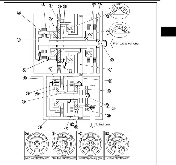
PFP:31036
ECS00A0T
SCIA2575E
1. |
Converter housing |
2. |
2nd brake |
3. |
One-way clutch No. 2 |
4. |
Control valve assembly |
5. |
Side cover |
6. |
1st and reverse brake |
7. |
Forward clutch |
8. |
Direct clutch |
9. |
Transaxle case cover |
10. |
B5 brake |
11. |
Transaxle case |
12. |
U/D clutch |
13. |
U/D brake |
14. |
Final gear |
15. |
Differential case |
16. |
Output shaft |
17. |
Counter driven gear |
18. |
Counter drive gear |
19. |
Input shaft |
20. |
Oil pump |
21. |
One-way clutch No. 1 |
22. |
2nd coast brake |
23. |
Torque converter |
24. |
Main rear planetary gear |
25. |
Main front planetary gear |
26. |
U/D rear planetary gear |
27. |
U/D front planetary gear |
Revision: July 2005 |
AT-16 |
2005 Maxima |
|
|
|
A/T CONTROL SYSTEM |
|
|
|
|
|
|
|
|
|
|
|
|
|
|
|
|
|
|
Shift Mechanism |
|
|
|
|
ECS00A0U |
|||||
CONSTRUCTION |
|
|
|
|
|
|
|
A |
||
|
|
|
|
|
|
|
|
|
|
B |
|
|
|
|
|
|
|
|
|
|
|
|
|
|
|
|
|
|
|
|
|
|
|
|
|
|
|
|
|
|
|
|
AT |
|
|
|
|
|
|
|
|
|
|
|
|
|
|
|
|
|
|
|
|
|
D |
|
|
|
|
|
|
|
|
|
|
E |
|
|
|
|
|
|
|
|
|
|
F |
|
|
|
|
|
|
|
|
|
|
G |
|
|
|
|
|
|
|
|
|
|
H |
|
|
|
|
|
|
|
|
|
|
I |
|
|
|
|
|
|
|
|
|
|
J |
|
|
|
|
|
|
|
SCIA2576E |
|
||
1. |
Forward clutch |
2. |
Direct clutch |
3. |
U/D clutch |
|
|
|
K |
|
4. |
2nd coast brake |
5. |
2nd brake |
6. 1st and reverse brake |
|
|
|
|
||
7. |
U/D brake |
8. |
B5 brake |
9. One-way clutch No. 1 |
|
|
|
|
||
10. |
One-way clutch No. 2 |
11. |
Main sun gear |
12. |
Main planetary carrier |
|
|
|
L |
|
13. |
Main front internal gear |
14. |
Main rear internal gear |
15. |
U/D sun gear |
|
|
|
|
|
16. |
U/D front planetary carrier |
17. |
U/D front internal gear |
18. |
U/D rear planetary carrier |
|
|
|
|
|
19. |
U/D rear internal gear |
20. |
Input shaft |
21. |
Counter drive gear |
|
|
|
M |
|
22. |
Counter driven gear |
23. |
Output shaft |
24. |
Parking gear |
|
|
|
|
|
25. |
Parking pawl |
|
|
|
|
|
|
|
|
|
Revision: July 2005 |
AT-17 |
2005 Maxima |

A/T CONTROL SYSTEM
FUNCTION OF CLUTCH AND BRAKE
Clutch and brake components |
Abbr. |
Function |
|
|
|
Forward clutch 1 |
F/C |
Connect input shaft 20 to main rear internal gear 10 . |
|
|
|
Direct clutch 2 |
D/C |
Connect input shaft 20 to main sun gear 11 . |
|
|
|
U/D clutch 3 |
U/D.C |
Connect U/D sun gear 15 to U/D front planetary carrier 16 . |
|
|
|
2nd coast brake 4 |
2nd C/B |
Lock main sun gear 11 . |
|
|
|
2nd brake 5 |
2nd/B |
Lock counterclockwise rotation of main sun gear 11 . |
|
|
|
1st and reverse brake 6 |
1st & R/B |
Lock main front internal gear 13 . |
|
|
|
U/D brake 7 |
U/D.B |
Lock U/D sun gear 15 . |
|
|
|
B5 brake 8 |
B5/B |
Lock U/D rear planetary carrier 18 . |
|
|
|
One-way clutch No. 1 9 |
O.C1 |
Lock counterclockwise rotation of main sun gear 11 , when 2nd brake 5 oper- |
|
|
ations. |
|
|
|
One-way clutch No. 2 10 |
O.C2 |
Lock counterclockwise rotation of main front internal gear 13 . |
|
|
|
CLUTCH AND BAND CHART
|
|
|
|
Clutch |
|
|
|
Brake |
|
|
One-way clutch |
|
|
||
|
|
|
|
|
|
|
|
|
|
|
|
|
|
|
|
Shift position |
F/C |
D/C |
U/D.C |
2nd C/ |
2nd/B |
1st & |
U/D.B |
B5/B |
O.C1 |
O.C2 |
Remarks |
||||
B |
R/B |
||||||||||||||
|
|
|
|
|
|||||||||||
|
|
|
1 |
2 |
3 |
5 |
7 |
8 |
9 |
10 |
|
|
|||
|
|
|
4 |
6 |
|
|
|||||||||
|
|
|
|
|
|
|
|
|
|
|
|
|
|||
|
|
|
|
|
|
|
|
|
|
|
|
|
|
||
|
P |
|
|
|
|
|
|
|
|
|
|
|
PARK |
||
|
|
|
|
|
|
|
|
|
|
|
|
POSITION |
|||
|
|
|
|
|
|
|
|
|
|
|
|
|
|||
|
|
|
|
|
|
|
|
|
|
|
|
|
|
||
|
R |
|
|
|
|
|
|
|
|
|
|
|
REVERSE |
||
|
|
|
|
|
|
|
|
|
|
|
|
POSITION |
|||
|
|
|
|
|
|
|
|
|
|
|
|
|
|||
|
|
|
|
|
|
|
|
|
|
|
|
|
|
||
|
N |
|
|
|
|
|
|
|
|
|
|
|
NEUTRAL |
||
|
|
|
|
|
|
|
|
|
|
|
|
POSITION |
|||
|
|
|
|
|
|
|
|
|
|
|
|
|
|||
|
|
|
|
|
|
|
|
|
|
|
|
|
|
|
|
|
1st |
|
|
|
|
|
|
|
|
|
|
|
|
|
|
|
|
|
|
|
|
|
|
|
|
|
|
|
|
|
|
|
1 |
2 |
|
|
|
|
|
|
|
|
|
|
|
|
|
|
|
|
|
|
|
|
|
|
|
|
|
|
|
||
|
2nd |
|
|
|
|
|
|
|
|
|
|
|
|
||
|
|
|
|
|
|
|
|
|
|
|
|
|
|
|
|
|
2 |
3 |
|
|
|
|
|
|
|
|
|
|
Automatic shift |
||
|
|
|
|
|
|
|
|
|
|
|
|
|
|||
|
|
|
|
|
|
|
|
|
|
|
|
|
|||
D |
3rd |
|
|
|
|
|
|
|
|
|
|
|
1 2 |
3 |
|
|
|
|
|
|
|
|
|
|
|
|
|
|
4 |
5 |
|
|
3 |
4 |
|
|
|
|
|
|
|
|
|
|
|||
|
|
|
|
|
|
|
|
|
|
|
|
|
|||
|
|
|
|
|
|
|
|
|
|
|
|
|
|
|
|
|
4th |
|
|
|
|
|
|
|
|
|
|
|
|
|
|
|
|
|
|
|
|
|
|
|
|
|
|
|
|
|
|
|
4 |
5 |
|
|
|
|
|
|
|
|
|
|
|
|
|
|
|
|
|
|
|
|
|
|
|
|
|
|
|
|
|
|
5th |
|
|
|
|
|
|
|
|
|
|
|
|
|
|
|
|
|
|
|
|
|
|
|
|
|
|
|
|
||
M5 |
5th |
|
|
|
|
|
|
|
|
|
|
|
Locks in 5th |
||
|
|
|
|
|
|
|
|
|
|
|
gear* |
||||
|
|
|
|
|
|
|
|
|
|
|
|
|
|||
|
|
|
|
|
|
|
|
|
|
|
|
|
|
||
M4 |
4th |
|
|
|
|
|
|
|
|
|
|
|
Locks in 4th |
||
|
|
|
|
|
|
|
|
|
|
|
gear* |
||||
|
|
|
|
|
|
|
|
|
|
|
|
|
|||
|
|
|
|
|
|
|
|
|
|
|
|
|
|
||
M3 |
3rd |
|
|
|
|
|
|
|
|
|
|
|
Locks in 3rd |
||
|
|
|
|
|
|
|
|
|
|
|
gear* |
||||
|
|
|
|
|
|
|
|
|
|
|
|
|
|||
|
|
|
|
|
|
|
|
|
|
|
|
|
|
||
M2 |
2nd |
|
|
|
|
|
|
|
|
|
|
Locks in 2nd |
|||
|
|
|
|
|
|
|
|
|
|
gear* |
|||||
|
|
|
|
|
|
|
|
|
|
|
|
|
|||
|
|
|
|
|
|
|
|
|
|
|
|
|
|
||
M1 |
1st |
|
|
|
|
|
|
|
|
|
|
|
Locks in 1st |
||
|
|
|
|
|
|
|
|
|
|
|
gear* |
||||
|
|
|
|
|
|
|
|
|
|
|
|
|
|||
|
|
|
|
|
|
|
|
|
|
|
|
|
|
|
|
 : Operates
 : In transition between applied and released.
*: Except when automated up/down shift control and up/down shift permission control are activated. Refer to AT-37, "MANUAL MODE" .
Revision: July 2005 |
AT-18 |
2005 Maxima |
A/T CONTROL SYSTEM
POWER TRANSMISSION |
|
“N” position |
A |
Since both the forward clutch and the direct clutch are released, torque from the input shaft drive is not transmitted to the output shaft.
B
“P” position
● The same as for the “N” position, both the forward clutch and the direct clutch are released, so torque
from the input shaft drive is not transmitted to the output shaft.
AT
●The parking pole linked with the selector lever meshes with the parking gear and fastens the output shaft mechanically.
D
E
F
G
H
I
J
K
L
M
SCIA2577E
1. |
Forward clutch |
2. |
Direct clutch |
3. |
U/D clutch |
4. |
2nd coast brake |
5. |
2nd brake |
6. |
1st and reverse brake |
7. |
U/D brake |
8. |
B5 brake |
9. |
One-way clutch No. 1 |
10. |
One-way clutch No. 2 |
11. |
Main sun gear |
12. |
Main planetary carrier |
13. |
Main front internal gear |
14. |
Main rear internal gear |
15. |
U/D sun gear |
16. |
U/D front planetary carrier |
17. |
U/D front internal gear |
18. |
U/D rear planetary carrier |
19. |
U/D rear internal gear |
20. |
Input shaft |
21. |
Counter drive gear |
22. |
Counter driven gear |
23. |
Output shaft |
24. |
Parking gear |
25. |
Parking pawl |
|
|
|
|
Revision: July 2005 |
AT-19 |
2005 Maxima |

A/T CONTROL SYSTEM
“D” position 1st gear
1.Input shaft rotates clockwise.
2.Forward clutch operates. (Connect input shaft to main rear internal gear.)
3.Main rear internal gear rotates clockwise.
4.Main rear planetary pinion gear rotates itself clockwise.
5.Main front large planetary pinion gear rotates itself clockwise for rear planetary pinion and one.
6.Main front small planetary pinion gear rotates itself counterclockwise.
7.Main front internal gear is going to rotates counterclockwise.
8.One-way clutch No. 2 operates. (Lock counterclockwise rotation of main front internal gear.)
9.Main planetary carrier revolves clockwise due to reaction force of front small planetary pinion gear.
10.Counter drive gear rotates clockwise for main planetary carrier and one.
11.Counter driven gear rotates counterclockwise.
12.U/D front internal gear rotates counterclockwise for counter driven gear and one.
13.U/D front planetary pinion gear rotates itself counterclockwise.
14.U/D sun gear rotates clockwise.
15.U/D rear planetary pinion gear rotates itself counterclockwise.
16.B5 brake operate. (Lock rotation of U/D rear planetary carrier.)
17.U/D rear internal gear rotates counterclockwise.
18.U/D front planetary carrier and output shaft rotates counterclockwise for U/D rear internal gear and one.
19.Final gear clockwise.
●During deceleration, main front internal gear clockwise due to rotation itself clockwise of main front small planetary pinion gear, but driving force loses due to free of one-way clutch No. 2. Therefore, engine brake does not operate.
Revision: July 2005 |
AT-20 |
2005 Maxima |
A/T CONTROL SYSTEM
A
B
AT
D
E
F
G
H
I
J
K
L
M
SCIA2585E
1. |
Forward clutch |
2. |
Direct clutch |
3. |
U/D clutch |
4. |
2nd coast brake |
5. |
2nd brake |
6. |
1st and reverse brake |
7. |
U/D brake |
8. |
B5 brake |
9. |
One-way clutch No. 1 |
10. |
One-way clutch No. 2 |
11. |
Main sun gear |
12. |
Main planetary carrier |
13. |
Main front internal gear |
14. |
Main rear internal gear |
15. |
U/D sun gear |
16. |
U/D front planetary carrier |
17. |
U/D front internal gear |
18. |
U/D rear planetary carrier |
19. |
U/D rear internal gear |
20. |
Input shaft |
21. |
Counter drive gear |
22. |
Counter driven gear |
23. |
Output shaft |
24. |
Parking gear |
25. |
Parking pawl |
|
|
|
|
Revision: July 2005 |
AT-21 |
2005 Maxima |

A/T CONTROL SYSTEM
“M1” position 1st gear
1.Input shaft rotates clockwise.
2.Forward clutch operates. (Connect input shaft to main rear internal gear.)
3.Main rear internal gear rotates clockwise.
4.Main rear planetary pinion gear rotates itself clockwise.
5.Main front large planetary pinion gear rotates itself clockwise for rear planetary pinion gear and one.
6.Main front small planetary pinion gear rotates itself counterclockwise.
7.Main front internal gear is going to rotates counterclockwise.
8.1st and reverse brake operates. (Lock rotation of main front internal gear.)
9.Main planetary carrier revolves clockwise due to reaction force of front small planetary pinion gear.
10.Counter drive gear rotates clockwise for main planetary carrier and one.
11.Counter driven gear rotates counterclockwise.
12.U/D front internal gear rotates counterclockwise for counter driven gear and one.
13.U/D front planetary pinion gear rotates itself counterclockwise.
14.U/D sun gear rotates clockwise.
15.U/D rear planetary pinion gear rotates itself counterclockwise.
16.B5 brake operate. (Lock rotation of U/D rear planetary carrier.)
17.U/D rear internal gear rotates counterclockwise.
18.U/D front planetary carrier and output shaft rotates counterclockwise for U/D rear internal gear and one.
19.Final gear clockwise.
●During deceleration, driving force is connected to input shaft directly without one-way clutch. Therefore, engine brake operates.
Revision: July 2005 |
AT-22 |
2005 Maxima |

A/T CONTROL SYSTEM
A
B
AT
D
E
F
G
H
I
J
K
L
M
SCIA2586E
1. |
Forward clutch |
2. |
Direct clutch |
3. |
U/D clutch |
4. |
2nd coast brake |
5. |
2nd brake |
6. |
1st and reverse brake |
7. |
U/D brake |
8. |
B5 brake |
9. |
One-way clutch No. 1 |
10. |
One-way clutch No. 2 |
11. |
Main sun gear |
12. |
Main planetary carrier |
13. |
Main front internal gear |
14. |
Main rear internal gear |
15. |
U/D sun gear |
16. |
U/D front planetary carrier |
17. |
U/D front internal gear |
18. |
U/D rear planetary carrier |
19. |
U/D rear internal gear |
20. |
Input shaft |
21. |
Counter drive gear |
22. |
Counter driven gear |
23. |
Output shaft |
24. |
Parking gear |
25. |
Parking pawl |
|
|
|
|
Revision: July 2005 |
AT-23 |
2005 Maxima |

A/T CONTROL SYSTEM
“D”, “M2” positions 2nd gear
1.Input shaft rotates clockwise.
2.Forward clutch operates. (Connect input shaft to main rear internal gear.)
3.Main rear internal gear rotates clockwise.
4.Main rear planetary pinion gear rotates itself clockwise.
5.Main front large planetary pinion gear rotates itself clockwise for rear planetary pinion and one.
6.2nd brake and 2nd coast brake operates.
7.One-way clutch No. 1 operates. (Lock rotation of main sun gear.)
8.Main planetary carrier revolves clockwise due to reaction force of front large planetary pinion gear.
9.Counter drive gear rotates clockwise for main planetary carrier and one.
10.Counter driven gear rotates counterclockwise.
11.U/D front internal gear rotates counterclockwise for counter driven gear and one.
12.U/D front planetary pinion gear rotates itself counterclockwise.
13.U/D sun gear rotates clockwise.
14.U/D rear planetary pinion gear rotates itself counterclockwise.
15.B5 brake operate. (Lock rotation of U/D rear planetary carrier.)
16.U/D rear internal gear rotates counterclockwise.
17.U/D front planetary carrier and output shaft rotates counterclockwise for U/D rear internal gear and one.
18.Final gear clockwise.
●During deceleration, driving force is connected to input shaft directly without one-way clutch. Therefore, engine brake operates.
Revision: July 2005 |
AT-24 |
2005 Maxima |
A/T CONTROL SYSTEM
A
B
AT
D
E
F
G
H
I
J
K
L
M
SCIA2587E
1. |
Forward clutch |
2. |
Direct clutch |
3. |
U/D clutch |
4. |
2nd coast brake |
5. |
2nd brake |
6. |
1st and reverse brake |
7. |
U/D brake |
8. |
B5 brake |
9. |
One-way clutch No. 1 |
10. |
One-way clutch No. 2 |
11. |
Main sun gear |
12. |
Main planetary carrier |
13. |
Main front internal gear |
14. |
Main rear internal gear |
15. |
U/D sun gear |
16. |
U/D front planetary carrier |
17. |
U/D front internal gear |
18. |
U/D rear planetary carrier |
19. |
U/D rear internal gear |
20. |
Input shaft |
21. |
Counter drive gear |
22. |
Counter driven gear |
23. |
Output shaft |
24. |
Parking gear |
25. |
Parking pawl |
|
|
|
|
Revision: July 2005 |
AT-25 |
2005 Maxima |

A/T CONTROL SYSTEM
“D”, “M3” positions 3rd gear
1.Input shaft rotates clockwise.
2.Forward clutch operates. (Connect input shaft to main rear internal gear.)
3.Main rear internal gear rotates clockwise.
4.Main rear planetary pinion gear rotates itself clockwise.
5.Main front large planetary pinion gear rotates itself clockwise for rear planetary pinion and one.
6.2nd brake and 2nd coast brake operates.
7.One-way clutch No. 1 operates. (Lock rotation of main sun gear.)
8.Main planetary carrier revolves clockwise due to reaction force of front large planetary pinion gear.
9.Counter drive gear rotates clockwise for main planetary carrier and one.
10.Counter driven gear rotates counterclockwise.
11.U/D front internal gear rotates counterclockwise for counter driven gear and one.
12.U/D front planetary pinion gear rotates itself counterclockwise.
13.U/D brake operate. (Lock rotation of U/D sun gear.)
14.U/D front planetary carrier revolves counterclockwise due to reaction force of U/D front planetary pinion gear.
15.U/D rear internal gear and output shaft rotates counterclockwise for U/D front planetary carrier and one.
16.Final gear clockwise.
●During deceleration, driving force is connected to input shaft directly without one-way clutch. Therefore, engine brake operates.
Revision: July 2005 |
AT-26 |
2005 Maxima |

A/T CONTROL SYSTEM
A
B
AT
D
E
F
G
H
I
J
K
L
M
SCIA2588E
1. |
Forward clutch |
2. |
Direct clutch |
3. |
U/D clutch |
4. |
2nd coast brake |
5. |
2nd brake |
6. |
1st and reverse brake |
7. |
U/D brake |
8. |
B5 brake |
9. |
One-way clutch No. 1 |
10. |
One-way clutch No. 2 |
11. |
Main sun gear |
12. |
Main planetary carrier |
13. |
Main front internal gear |
14. |
Main rear internal gear |
15. |
U/D sun gear |
16. |
U/D front planetary carrier |
17. |
U/D front internal gear |
18. |
U/D rear planetary carrier |
19. |
U/D rear internal gear |
20. |
Input shaft |
21. |
Counter drive gear |
22. |
Counter driven gear |
23. |
Output shaft |
24. |
Parking gear |
25. |
Parking pawl |
|
|
|
|
Revision: July 2005 |
AT-27 |
2005 Maxima |

A/T CONTROL SYSTEM
“D”, “M4” positions 4th gear
1.Input shaft rotates clockwise.
2.Forward clutch operates. (Connect input shaft to main rear internal gear.)
3.Main rear internal gear rotates clockwise.
4.Main rear planetary pinion gear rotates itself clockwise.
5.Main front large planetary pinion gear rotates itself clockwise for rear planetary pinion and one.
6.2nd brake and 2nd coast brake operates.
7.One-way clutch No. 1 operates. (Lock rotation of main sun gear.)
8.Main planetary carrier revolves clockwise due to reaction force of front large planetary pinion gear.
9.Counter drive gear rotates clockwise for main planetary carrier and one.
10.Counter driven gear rotates counterclockwise.
11.U/D front internal gear rotates counterclockwise for counter driven gear and one.
12.U/D clutch operate. (Connect U/D sun gear to U/D front planetary carrier.)
13.U/D front planetary pinion gear cannot rotate itself, and U/D unit rotates counterclockwise as one.
14.Output shaft rotates counterclockwise for U/D unit and one.
15.Final gear clockwise.
●During deceleration, driving force is connected to input shaft directly without one-way clutch. Therefore, engine brake operates.
Revision: July 2005 |
AT-28 |
2005 Maxima |

A/T CONTROL SYSTEM
A
B
AT
D
E
F
G
H
I
J
K
L
M
SCIA2592E
1. |
Forward clutch |
2. |
Direct clutch |
3. |
U/D clutch |
4. |
2nd coast brake |
5. |
2nd brake |
6. |
1st and reverse brake |
7. |
U/D brake |
8. |
B5 brake |
9. |
One-way clutch No. 1 |
10. |
One-way clutch No. 2 |
11. |
Main sun gear |
12. |
Main planetary carrier |
13. |
Main front internal gear |
14. |
Main rear internal gear |
15. |
U/D sun gear |
16. |
U/D front planetary carrier |
17. |
U/D front internal gear |
18. |
U/D rear planetary carrier |
19. |
U/D rear internal gear |
20. |
Input shaft |
21. |
Counter drive gear |
22. |
Counter driven gear |
23. |
Output shaft |
24. |
Parking gear |
25. |
Parking pawl |
|
|
|
|
Revision: July 2005 |
AT-29 |
2005 Maxima |

A/T CONTROL SYSTEM
“D”, “M5” positions 5th gear
1.Input shaft rotates clockwise.
2.Forward clutch operates. (Connect input shaft to main rear internal gear.)
3.Direct clutch operates. (Connect input shaft to main sun gear.)
4.Main rear planetary pinion gear cannot rotate itself, and main rear planetary unit rotates clockwise as one.
5.Main front large planetary pinion gear cannot rotate itself for main rear planetary pinion gear and one, and main front planetary unit rotates clockwise as one.
6.Counter drive gear rotates clockwise for main front planetary unit and one.
7.Counter driven gear rotates counterclockwise.
8.U/D front internal gear rotates counterclockwise for counter driven gear and one.
9.U/D clutch operate. (Connect U/D sun gear to U/D front planetary carrier.)
10.U/D front planetary pinion gear cannot rotate itself, and U/D unit rotates counterclockwise as one.
11.Output shaft rotates counterclockwise for U/D unit and one.
12.Final gear clockwise.
●During deceleration, driving force is connected to input shaft directly without one-way clutch. Therefore, engine brake operates.
Revision: July 2005 |
AT-30 |
2005 Maxima |
Loading...