


 Loading...
RESTRAINT SYSTEM
SECTION RS
CONTENTS
PRECAUTION............................................................ |
2 |
Removal Ð Front Passenger's Air Bag .............. |
16 |
|
Supplemental Restraint System (SRS) ``AIR |
|
Installation Ð Front Passenger's Air Bag |
|
|
BAG'' and ``SEAT BELT PRE-TENSIONER'' ........ |
2 |
Module ................................................................. |
17 |
|
SEAT BELT ............................................................... |
3 |
Removal Ð Side Air Bag Module........................ |
17 |
|
Front Seat Belt....................................................... |
3 |
Installation Ð Side Air Bag Module..................... |
18 |
|
Rear Seat Belt (4-door models)............................. |
4 |
Disposal of Air Bag Module and Seat Belt Pre- |
|
|
SEAT BELT ............................................................... |
6 |
tensioner .............................................................. |
20 |
|
Rear Seat Belt (Wagon and 5-door models)......... |
6 |
TROUBLE DIAGNOSES Ð Supplemental |
|
|
SUPPLEMENTAL RESTRAINT SYSTEM (SRS) ..... |
8 |
Restraint System (SRS) ......................................... |
25 |
|
Precautions for SRS ``AIR BAG'' and ``SEAT |
|
Trouble Diagnoses Introduction........................... |
25 |
|
BELT PRE-TENSIONER'' Service......................... |
8 |
How to Perform Trouble Diagnoses for Quick |
|
|
Special Service Tools ............................................ |
8 |
and Accurate Repair ............................................ |
27 |
|
Description ............................................................. |
9 |
Schematic ............................................................ |
29 |
|
SRS Component Parts Location.......................... |
10 |
Wiring Diagram Ð SRS Ð .................................. |
30 |
|
Maintenance Items............................................... |
11 |
SRS-Operation Check ......................................... |
35 |
|
Removal and Installation Ð Diagnosis Sensor |
|
............Trouble Diagnoses with CONSULT-II |
36 |
RS |
Unit, Seat Belt Pre-tensioner and Satellite |
|
Trouble Diagnoses without CONSULT-II ....... |
45 |
|
..................................................................Sensor |
12 |
...Trouble Diagnoses for Air Bag Warning Lamp |
52 |
|
Removal Ð Air Bag Module and Spiral Cable.... |
13 |
COLLISION DIAGNOSIS......................................... |
54 |
|
Installation Ð Air Bag Module and Spiral |
|
|
|
|
Cable.................................................................... |
15 |
|
|
|
When you read wiring diagrams:
●Read GI section, ``HOW TO READ WIRING DIAGRAMS''.
●See EL section, ``POWER SUPPLY ROUTING'' for power distribution circuit.
●See EL section for NATS information and wiring diagram.
When you perform trouble diagnoses, read GI section, ``HOW TO FOLLOW FLOW CHART IN TROUBLE DIAGNOSES'' and ``HOW TO PERFORM EFFICIENT DIAGNOSIS FOR AN ELECTRICAL INCIDENT''.

PRECAUTION
Supplemental Restraint System (SRS) ``AIR
BAG'' and ``SEAT BELT PRE-TENSIONER''
The Supplemental Restraint System such as ``AIR BAG'' and ``SEAT BELT PRE-TENSIONER'' used along with a seat belt, help to reduce the risk or severity of injury to the driver and front passenger in certain types of collision. The SRS system composition which is available to NISSAN MODEL P11 is as follows (The composition varies according to the destination and optional equipment):
●For a frontal collision
The Supplemental Restraint System consists of driver's air bag module (located in the center of the steering wheel), front passenger's air bag module (located on the instrument panel on passenger's side), seat belt pre-tensioners, a diagnosis sensor unit, warning lamp, wiring harness and spiral cable.
●For a side collision
The Supplemental Restraint System consists of air bag modules (located in the outer side of front seats), satellite sensor, diagnosis sensor unit (one of components of supplemental air bags for a frontal collision), wiring harness, warning lamp (one of components of supplemental air bags for a frontal collision).
WARNING:
●To avoid rendering the SRS inoperative, which could increase the risk of personal injury or death in the event of a collision which would result in air bag inflation, all maintenance must be performed by an authorized NISSAN dealer.
●Improper maintenance, including incorrect removal and installation of the SRS, can lead to personal injury caused by unintentional activation of the system.
●Do not use electrical test equipment on any circuit related to the SRS unless instructed to in this Service Manual. Spiral cable and SRS wiring harnesses except ``SEAT BELT PRE-TENSIONER'' connectors can be identified by yellow harness connector (and with yellow harness protector or yellow insulation tape before the harness connectors).
CAUTION:
●Before removing the seat belt pre-tensioner assembly, turn the ignition switch off, disconnect both battery cables and wait at least 3 minutes.
●Do not use electrical test equipment for seat belt pre-tensioner connector.
●After replacing or installing seat belt pre-tensioner assembly, or reconnecting seat belt pre-ten- sioner connector, check the system function. Refer to ``SRS Operation Check'' (RS-35) for details.
●Do not disassemble buckle or seat belt assembly.
●Replace anchor bolts if they are deformed or worn out.
●Never oil tongue and buckle.
●If any component of seat belt assembly is questionable, do not repair. Replace the whole seat belt assembly.
●If webbing is cut, frayed, or damaged, replace seat belt assembly.
●When replacing seat belt assembly, use a genuine seat belt assembly.
●After any collision, inspect all seat belt assemblies, including retractors and other attached hardwares (i.e., guide rail set).
RS-2
SEAT BELT
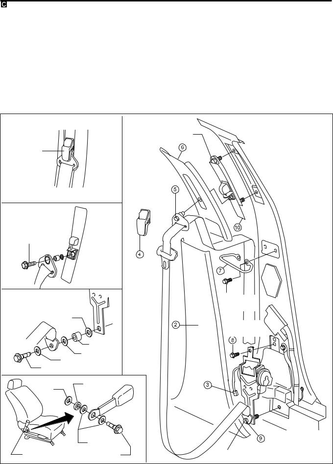
Front Seat Belt
V1 Slide the seat all the way forward.
V2 Remove center pillar lower garnish. Refer to ``INTERIOR TRIM'' in BT section for details. V3 Disconnect seat belt pre-tensioner subharness connector from the main harness.
V4 Remove the cover of the shoulder adjustment.
V5 Remove the seat belt from the shoulder adjuster.
V6 Remove center pillar upper garnish. Refer to ``INTERIOR TRIM'' in BT section for details. V7 Remove bolts securing sash guide, then remove sash guide.
V8 Remove the seat belt pre-tensioner retractor anchor bolt.
V9 Remove the bolt securing seat belt pre-tensioner retractor, then remove seat belt and seat belt pre-ten- sioner retractor.
V10 Remove shoulder adjustment, taking care not to damage plastic garnish.
Adjuster cover
43 - 55
(4.4 - 5.6,
32 - 41)
Washer
Bush
Washer
Washer
Anchor bolt 
Bush
Toothed
Washer
|
Washer |
|
43 - 55 |
Anchor bolt |
|
(4.4 - 5.6, 32 - 41) |
||
|
43 - 55
(4.4 - 5.6, 32 - 41)
.
5.1 - 6.3
(0.52 - 0.64,
45 - 56)
.
5.1 - 6.3
(0.52 - 0.64,
45 - 56)
.
.
43 - 55
(4.4 - 5.6, 32 - 41)
:N´m (kg-m, ft-lb)
:N´m (kg-m, in-lb)
:Do not re-use NRS054
RS-3
SEAT BELT
Rear Seat Belt (4-door models)
MODELS WITH 2-POINT CENTER SEAT BELT
V1 Remove rear seat cushion. Refer to ``SEAT'' in BT-section for details.
V2 Remove each anchor bolt.
V3 Remove both sides of the back of the seat.
V4 Fold down rear seat.
V5 Remove high mounted stop lamp from parcel shelf (where fitted).
V6 Remove rear pillar garnish.
V7 Remove the parcel shelf.
V8 Remove the bolt and screw which secure the rear seat belt retractors.
. |
|
Child seat anchorage |
|
43 - 55 |
|
(4.4 - 5.6, |
|
32 - 41) |
|
2.0 - 3.0 |
|
(0.2 - 0.31, 1 - 2) |
|
43 - 55 |
|
(4.4 - 5.6, |
|
32 - 41) |
|
. |
: N´m (kg-m, ft-lb) |
|
|
|
: N´m (kg-m, in-lb) |
|
NRS055 |
RS-4 |
|

SEAT BELT
Rear Seat Belt (4-door models) (Cont'd)
MODELS WITH 3-POINT CENTER SEAT BELT:
For outboard seat belts refer to ``models with 2 point center seat belt''.
V1 Remove rear seat cushion. Refer to ``SEAT'' in BT-section for details.
V2 Remove anchor bolts.
V3 Fold down LH-side backrest.
V4 Remove finisher located behind the armrest (where fitted).
V5 Remove trim on the rearside of the backrest.
V6 Remove finisher.
V7 Remove anchor bolt.
V8 Pull the retractor out of the backrest.
|
. |
|
|
43 - 55 |
|
. |
(4.4 - 5.6, |
|
32 - 41) |
|
|
Child seat anchorage |
|
|
43 - 55 |
|
|
(4.4 - 5.6, 32 - 41) |
|
|
|
B |
Tightening sequence |
|
43 - 55 |
A: finger tight |
|
B: 43 - 55 (4.4 - 5.6, |
|
|
(4.4 - 5.6, |
|
|
32 - 41) |
|
|
32 - 41) |
|
|
C: 43 - 55 (4.4 - 5.6, |
|
|
|
|
|
|
32 - 41) |
|
A, C |
|
|
N´m (kg-m, ft-lb) |
|
|
|
NRS056 |
|
RS-5 |
|

SEAT BELT
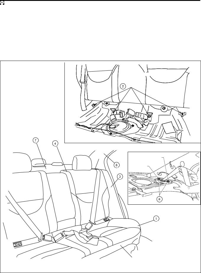
Rear Seat Belt (Wagon and 5-door models)
MODELS WITH 2-POINT CENTER SEAT BELT
V1 Remove rear seat cushion. Refer to ``SEAT'' in BT-section for details.
V2 Remove each anchor bolt.
V3 Fold down rear seat back.
V4 Remove rear seat back carpet and clips.
V5 Remove seat belt retractor escutcheon.
V6 Unclip rear seat back lock release button then remove the lock release escutcheon. V7 Remove fabric covering portion of the seat belt retractor.
V8 Remove the seat belt retractor cover.
V9 Loosen the seat belt retractor anchor bolt, then remove the seat belt retractor. V10 Remove interlock cable end from the seat belt retractor. (If necessary)
MODELS WITH 3-POINT CENTER SEAT BELT
The procedure is same as 2-point center seat belt models.
When removing 3-point center seatbelt, the procedure V6 should be skipped.
RS-6

SEAT BELT
Rear Seat Belt (Wagon and 5-door models) (Cont'd)
|
|
. |
|
|
|
Child seat anchorage |
|
|
|
43 - 55 |
|
|
|
(4.4 - 5.6, 32 - 41) |
|
|
6 |
|
|
|
5 |
|
|
|
|
|
Clip |
|
|
4 |
|
|
|
. |
|
|
|
Rear seat back |
|
|
|
Suitable |
|
|
|
tool |
|
|
|
|
PUSH |
|
|
6 |
|
|
|
9 |
|
|
1 |
43 - 55 |
|
|
(4.4 - 5.6, |
|
|
|
|
32 - 41) |
|
|
B |
10 |
Clip |
|
10 |
||
5 |
Seat belt |
|
|
|
|
||
|
|
|
|
|
retractor |
|
|
|
Pawl |
Seat belt |
|
|
retractor |
|
|
|
8 |
Pawl |
NRS057 |
|
RS-7 |
|
|
SUPPLEMENTAL RESTRAINT SYSTEM (SRS)
Precautions for SRS ``AIR BAG'' and ``SEAT
BELT PRE-TENSIONER'' Service
●Do not use electrical test equipment to check the SRS unless instructed to do in this Service Manual.
●Before servicing the SRS, turn ignition switch ``OFF'', disconnect both battery cables and wait at least 3 minutes.
For approximately 3 minutes after the cables are removed, it is still possible for the air bag and seat belt pre-tensioner to deploy. Therefore, do not work on any SRS connectors or wires until at least 3 minutes have passed.
●Diagnosis sensor unit must always be installed with their arrow marks ``S'' pointing towards the front of the vehicle for proper operation. Also check diagnosis sensor unit for cracks, deformities or rust before installation and replace as required.
●The spiral cable must be aligned with the neutral position since its rotations are limited. Do not attempt to turn steering wheel or column after removal of steering gear.
●Handle air bag module carefully. Always place driver's and passenger's air bag modules with the pad side facing upward and place side air bag module (built-in type) standing with stud bolt side setting bottom.
●Conduct self-diagnosis to check entire SRS for proper function after replacing any components.
●After air bag inflates, the front instrument panel assembly should be replaced if damaged.
|
Special Service Tools |
|
|
|
|
Tool number |
Description |
|
Tool name |
||
|
||
|
|
|
KV99106400 |
Disposing of air bag module |
|
Deployment tool |
|
|
NT357 |
KV999R0040 |
For seatbelt |
Deployment tool adapt- |
pretensioner |
|
|
ers for seat belt pre- |
|
tensioner |
|
|
NRS032 |
KV99105300 |
Anchoring air bag module |
Air bag module bracket |
|
|
NRS016 |
|
|
|
|
|
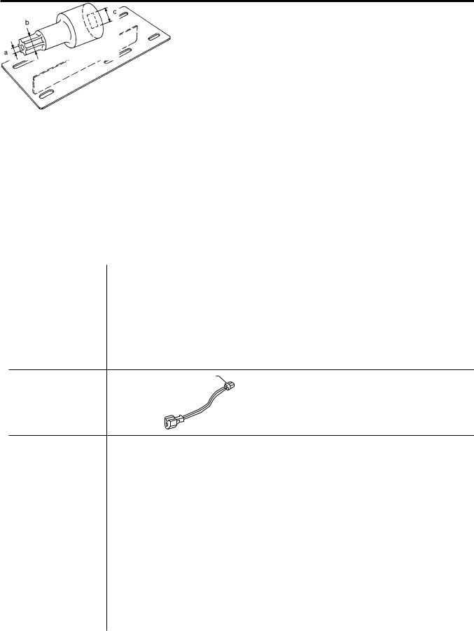
HT61961000 and |
Use for special bolts |
|
HT62152000 combined |
[TAMPER RESISTANT TORX (Size T50)] |
|
*Special torx bit |
a: 3.5 (0.138) dia. |
|
|
|
|
|
b: 8.5 - 8.6 (0.335 - 0.339) dia. |
|
|
c: approx. 10 (0.39) sq. |
|
NT361 |
Unit: mm (in) |
|
|
|
*: Special tool or commercial equivalent |
|
|
RS-8
SUPPLEMENTAL RESTRAINT SYSTEM (SRS)
Special Service Tools (Cont'd)
Tool number
Description
Tool name
KV99108300 Deployment tool adapters for Passenger and built-in type side air bag modules
NT770
*: Special tool or commercial equivalent
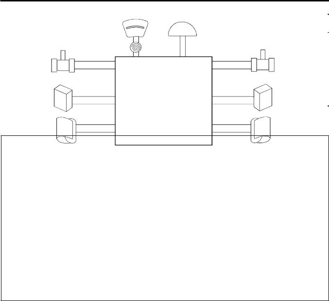
Description
|
Driver's air bag |
Passenger's air bag |
|
|
|
module |
module |
|
|
Seat belt pre-tensioner |
Diagnosis sensor unit |
|
Seat belt pre-tensioner |
|
|
(passenger's side) |
|||
(Driver's side) |
|
|||
|
|
|
||
|
|
|
|
|
|
· |
Auxiliary power source (condenser) |
|
|
|
· |
Drive circuit |
|
|
Satellite sensor (LH) |
· |
CPU |
|
Satellite sensor (RH) |
· |
G sensor |
|
(G sensor for side air bag |
|
(G sensor for side |
|
|||
|
(for driver's and passenger's air bags, |
RH) |
||
air bag LH) |
|
|||
|
seat belt pre-tensioner) |
|
||
|
|
|
||
|
· |
Safing sensor |
|
|
Side air bag module (LH) |
|
(for driver's and passenger's air bags, |
Side air bag module |
|
|
seat belt pre-tensioner) |
|||
(Built-in type) |
· |
Safing sensor |
|
(RH) (Built-in type) |
|
|
|
||
(for side air bag)
SRS585
The air bag deploys if the diagnosis sensor unit activates while the ignition switch is in ``ON'' or ``START'' position.
The collision modes for which supplemental restraint systems are activated are different among the SRS systems. For example, the driver's air bag module and passenger's air bag module are activated in a frontal collision but not in a side collision.
SRS configurations which are activated for some collision modes are as follows;
SRS configuration |
Frontal collision |
Left side collision |
Right side collision |
|
|
|
|
Driver's air bag module |
j |
Ð |
Ð |
|
|
|
|
Passenger's air bag module |
j |
Ð |
Ð |
|
|
|
|
Seat belt pre-tensioner (Driver's side) |
j |
Ð |
Ð |
|
|
|
|
Seat belt pre-tensioner (Passenger's side) |
j |
Ð |
Ð |
|
|
|
|
Side air bag module (LH) |
Ð |
j |
Ð |
|
|
|
|
Side air bag module (RH) |
Ð |
Ð |
j |
|
|
|
|
RS-9
SUPPLEMENTAL RESTRAINT SYSTEM (SRS)
.
Front seat back with front side air bag (Built-in type)
Built-in Type Side Air Bag
Front side air bag is built-in type.
The front seat back with built-in type side air bag has the labels as shown on the left figure.
NRS059
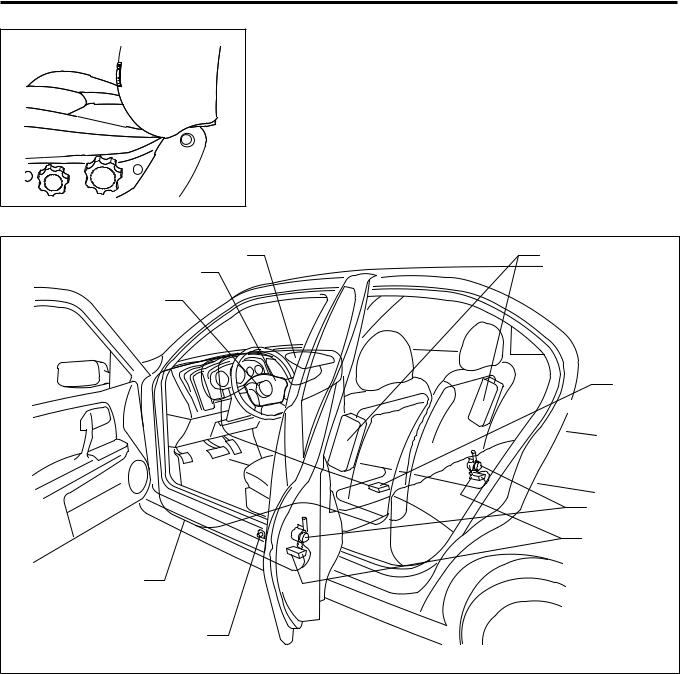
SRS Component Parts Location
Passenger's air bag module |
. |
Side air bag modules |
|
Driver's air bag module |
(Built-in type) |
|
|
Spiral cable |
|
|
Diagnosis |
|
sensor unit |
|
Seat belt preten- |
|
sioner retractors |
|
Satellite sensors |
Wiring harness |
|
Driver's side door switch |
|
|
NRS060 |
RS-10
SUPPLEMENTAL RESTRAINT SYSTEM (SRS)
|
Maintenance Items |
||
|
CAUTION: |
||
|
Do not use electrical test equipment to check SRS circuit. |
||
|
1. |
Check operation of ``AIR BAG'' warning lamp. |
|
|
|
After turning ignition key to ``ON'' position, the ``AIR BAG'' |
|
|
|
warning lamp illuminates. The ``AIR BAG'' warning lamp will |
|
|
|
go off after about 7 seconds if no malfunction is detected. |
|
|
|
If any of the following warning lamp conditions occur, imme- |
|
|
|
diately check the air bag system. Refer to ``SRS-Operation |
|
SBF806E |
|
Check'' for details. (RS-35) |
|
● |
The ``AIR BAG'' warning lamp does not come on when the |
||
|
|||
|
|
ignition switch is turned ``ON''. |
|
|
● |
The ``AIR BAG'' warning lamp does not go off about 7 sec- |
|
|
|
onds after the ignition switch is turned ``ON''. |
|
|
● |
The ``AIR BAG'' warning lamp goes off about 7 seconds after |
|
|
|
the ignition switch is turned ``ON'', but comes on again or |
|
|
|
flashes. |
|
2. Visually check SRS components.
(1) Diagnosis sensor unit
●Check diagnosis sensor unit and bracket for dents, cracks or deformities.
●Check connectors for damage, and terminals for deformities.
(2) Air bag module and steering wheel
●Remove air bag module from steering wheel, instrument panel or seat back. Check harness cover and connectors for damage, terminals for deformities, and harness for binding.
●Install driver's air bag module to steering wheel to check fit or alignment with the wheel.
●Check steering wheel for excessive free play.
●Install passenger's air bag module to instrument panel to check fit or alignment with the instrument panel.
●Install side air bag module to seatback to check fit and alignment with the seat.
(3) Spiral cable
●Check spiral cable for dents, cracks, or deformities.
●Check connectors and protective tape for damage.
●Check steering wheel for noise, binding or heavy operation.
(4) Main harness, body harness and air bag harness
●Check connectors for poor connections, damage, and terminals for deformities.
●Check harnesses for binding, chafing or cuts.
(5) Seat belt pre-tensioner
●Check harness cover and connectors for damage, terminals for deformities, and harness for binding.
●Check belts for damage and anchors for loose mounting.
●Check retractor for smooth operation.
●Perform self-diagnosis for seat belt pre-tensioner using CONSULT-II. Refer to ``Self-diagnosis'' for details. (RS-36)
(6) Satellite sensor
●Check satellite sensor (including bracket portion) for dents, cracks or deformities.
●Check connectors for damage, and terminals for deformities.
RS-11
SUPPLEMENTAL RESTRAINT SYSTEM (SRS)
CAUTION:
Replace previously used special bolts, ground bolt and nuts coated with bonding agent and also the anchor bolt with new ones.
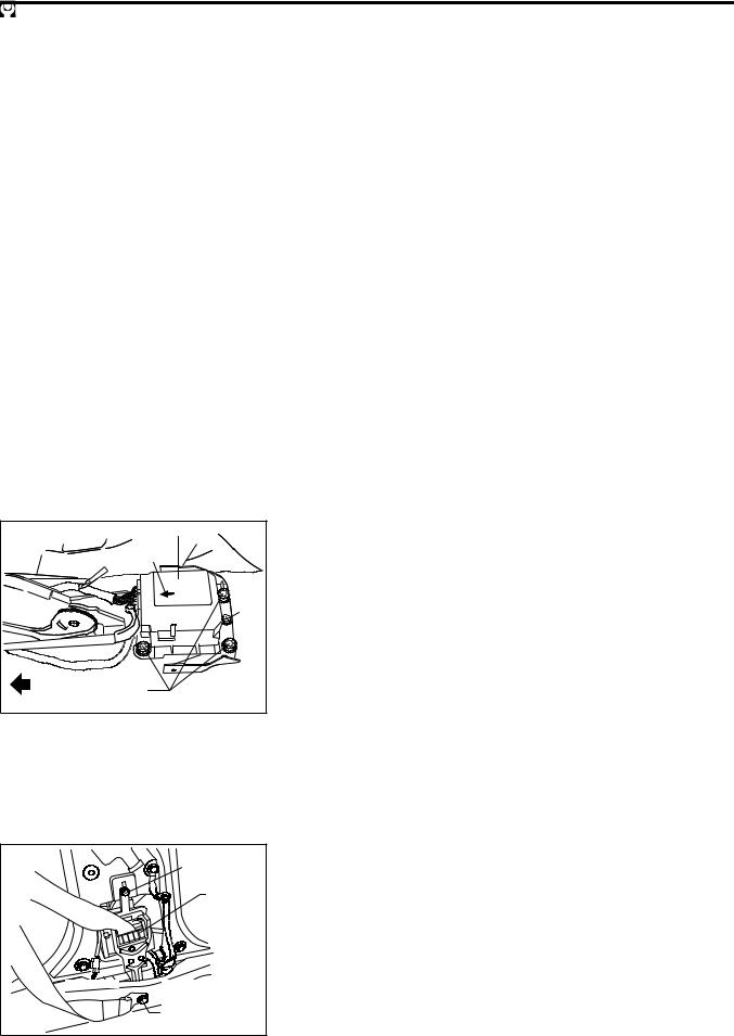
Removal and Installation Ð Diagnosis
Sensor Unit, Seat Belt Pre-tensioner and
Satellite Sensor
CAUTION:
●Before servicing SRS, turn the ignition switch ``OFF'', disconnect both battery cables and wait at least 3 minutes.
●The special bolts are coated with bonding agent while the other bolt is for ground. Do not use old bolts after removal; replace with new ones.
●Check diagnosis sensor unit, seat belt pre-tensioner and satellite sensor for proper installation.
●Check diagnosis sensor unit and satellite sensor to ensure they are free of deformities, dents, cracks or rust. If it shows any visible signs of damage, replace them with new ones.
●Check diagnosis sensor unit brackets to ensure they are free of deformities and rust.
●After replacement of diagnosis sensor unit, seat belt pre-tensioner and satellite sensor check SRS function and perform self-diagnosis for SRS. Refer to ``SRS Operation Check'' for details. (RS-35)
●Do not attempt to disassemble diagosis sensor unit,seat belt pre-tensioner and satellite sensor
●Replace diagnosis sensor unit, seat belt pre-tensioner and satellite sensor if it has been dropped or sustained an impact.
●Do not expose seat belt pre-tensioner to temperatures exceeding 80°C (176°F).
|
Diagnosis sensor unit |
|
|
. |
|
|
Forward mark |
|
|
|
Ground |
|
|
bolt |
|
Special bolt |
|
|
15 - 25 N´m |
|
FRONT |
(1.5 - 2.5 kg-m, 11 - 18 ft-lb) |
NRS061 |
REMOVAL OF DIAGNOSIS SENSOR UNIT
1.Disconnect driver's, passenger's- and side air bag module connectors. Also, disconnect seat belt pre-tensioner connector.
2.Remove lower instrument center panel. Refer to ``INSTRUMENT PANEL'' in BT section.
3.Disconnect diagnosis sensor unit connector.
4.Remove ground bolt and the special bolts by using the TAMPER RESISTANT TORX (Size T50), from diagnosis sensor unit.
Then remove the diagnosis sensor unit.
NOTE:
●To install, reverse the removal procedure sequence.
●Diagnosis sensor unit must always be installed with their arrow marks ``S'' pointing towards the front of the vehicle for proper installation.
.
5.1 - 6.3 N´m
(0.52 - 0.64 kg-m,
45 - 56 in-lb)
.
Seat belt pre-tensioner
. |
connector |
. |
|
Anchor bolt |
43 - 55 N´m
(4.4 - 5.6 kg-m,
32 - 41 ft-lb) NRS062
REMOVAL OF SEAT BELT PRE-TENSIONER
For removal of seat belt pre-tensioner, refer to ``Front Seat Belt'' for details. (RS-3)
NOTE:
●To install, reverse the removal procedure sequence.
RS-12
|
SUPPLEMENTAL RESTRAINT SYSTEM (SRS) |
|
|
|
Removal and Installation Ð Diagnosis |
|
|
Sensor Unit, Seat Belt Pre-tensioner and |
|
|
Satellite Sensor (Cont'd) |
|
|
REMOVAL SATELLITE SENSOR |
|
. |
1. Remove seat belt pre-tensioner. Refer to ``Front Seat Belt'' |
|
Ground bolt |
|
|
2.94 - 4.9 |
for details. (RS-3) |
|
(0.30 - 0.50, |
|
|
2. Disconnect satellite sensor connector. |
|
|
2 - 4) |
|
|
|
3. Remove bolt and nuts from satellite sensor unit. Then |
|
|
remove the satellite sensor. |
|
|
NOTE: |
|
|
● To install, reverse the removal procedure sequence. |
14.5 - 24.5 |
|
|
(1.5 - 2.5, 11 - 12) |
Connector |
|
: N´m (kg-m, ft-lb) |
|
|
|
|
|
: N´m (kg-m, in-lb) |
NRS063 |
|
|
|
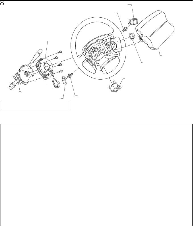
Removal Ð Air Bag Module and Spiral Cable |
SEC. 253c484 |
|
Side lid RH |
|
|
|
|
|
Special bolt |
|
|
15 - 25 (1.5 - 2.5, 11 - 18) |
Spiral cable |
|
|
Air bag module |
|
29 - 39 (3.0 - 4.0, 22 - 29) |
|
Lower lid |
|
: Do not re-use |
Combination switch |
N´m (kg-m, ft-lb) |
Special bolt |
|
Side lid LH |
15 - 25 (1.5 - 2.5, 11 - 18) |
NRS008 |
RS-13
SUPPLEMENTAL RESTRAINT SYSTEM (SRS)
Removal Ð Air Bag Module and Spiral Cable (Cont'd)
CAUTION:
●Before servicing SRS, turn the ignition switch ``OFF'', disconnect both battery cables and wait for at least 3 minutes.
●Always work from the side of air bag module.
1.Remove lower lid from steering wheel, and disconnect air bag module connector.
SBF811E
2.Remove side lids. Using the TAMPER RESISTANT TORX (Size T50), remove left and right special bolts.
Air bag module can then be removed.
Special bolt
SBF812E
CAUTION:
●Always place air bag module with pad side facing upward.
●Do not attempt to disassemble air bag module.
●The special bolts are coated with bonding agent. Do not use old bolts after removal; replace with new ones.
●Do not insert any foreign objects (screwdriver, etc.) into air bag module connector.
SBF813E
Air bag module
●Replace air bag module if it has been dropped or sustained an impact.
●Do not expose the air bag module to temperatures exceeding 90°C (194°F).
●Do not allow oil, grease or water to come in contact with the air bag module.
SBF814E
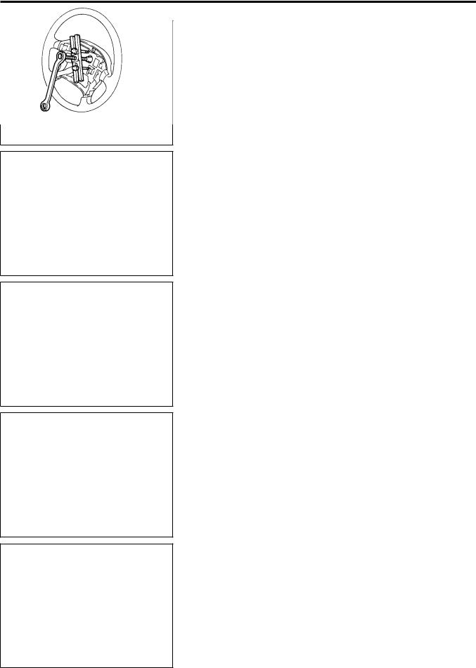
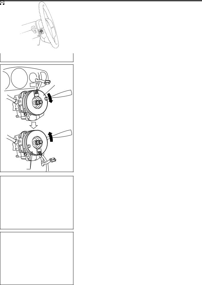
3.Set steering wheel in the neutral position, with the front wheels straight ahead.
4.Disconnect horn connector and remove nut.
5.Using steering wheel puller, remove steering wheel. Be careful not to over-tighten puller bolt on steering wheel.
CAUTION:
●Do not tap or bump the steering wheel.
6. Remove steering column cover.
SBF239F
RS-14
SUPPLEMENTAL RESTRAINT SYSTEM (SRS)
|
Removal Ð Air Bag Module and Spiral Cable |
|
|
(Cont'd) |
|
Connector |
7. |
Disconnect connector and remove the four screws. The spi- |
|
ral cable can then be removed. |
|
Unlock |
|
|
Lock |
|
|
|
CAUTION: |
|
|
● |
Do not attempt to disassemble spiral cable. |
|
● |
Do not apply lubricant to the spiral cable. |
SRS384 |
|
|
|
Installation Ð Air Bag Module and Spiral |
|
|
Cable |
|
|
1. |
Set the front wheels in the straight-ahead position. |
Alignment mark |
2. |
Make sure that the spiral cable is in the neutral position. |
|
|
The neutral position is detected by turning left about 2.5 |
|
|
revolutions from the right end position. Align the two marks |
|
|
( ). |
CAUTION:
● The spiral cable may snap during steering operation if the cable is installed incorrectly.
●Also, with the steering linkage disconnected, the cable
may snap by turning the steering wheel beyond the limited number of turns.
(The spiral cable can be turned up to 2.5 turns from the neutral position to both the right and left.)
3. Connect spiral cable connector and tighten with screws. Install steering column cover.
Alignment mark |
NRS070 |
SRS076
Special bolt
15 - 25 N´m
(1.5 - 2.5 kg-m,
11 - 18 ft-lb)
SBF812EA
4.Install steering wheel setting spiral cable pin guides, and pull spiral cable through.
5.Connect horn connector and engage spiral cable with pawls in steering wheel. Move other connectors away from steering wheel lower lid opener.
6.Tighten nut.
 : 29 - 39 N´m (3.0 - 4.0 kg-m, 22 - 29 ft-lb)
7.Position air bag module and tighten with new special bolts.
● Always service the air bag module from the side.
8.Connect other connectors.
9.Install all lids.
10.Connect both battery cables.
11.Conduct self-diagnosis to ensure entire SRS operates properly. (Use CONSULT-II or warning lamp check.)
12.Turn steering wheel to the left end and then to the right end fully to make sure that spiral cable is set in the neutral position.
If air bag warning lamp blinks or stays ON (at the user mode),
RS-15
SUPPLEMENTAL RESTRAINT SYSTEM (SRS)
Installation Ð Air Bag Module and Spiral
Cable (Cont'd)
.
Connector
.
NRS009
.
Remove special bolts
it shows the spiral cable may be snapped due to its improper position. Perform self-diagnosis again (use CONSULT-II or warning lamp). If a malfunction is detected, replace the spiral cable with a new one.
13.Perform self-diagnosis again to check that no malfunction is detected.
Removal Ð Front Passenger's Air Bag
Module
CAUTION:
●Before servicing SRS, turn the ignition switch ``OFF'', disconnect both battery cables and wait at least 3 minutes.
●Always work from the side of or under air bag module.
1.Open the glove box lid.
2.Disconnect inflator connector from body harness air bag connector.
3.Remove glove box assembly. Refer to ``INSTRUMENT PANEL'' in BT section for details.
4.Remove the bolts and special bolts using the TAMPER RESISTANT TORX (Size T50) from front passenger's air bag module.
Take out the air bag module from the instrument panel.
●The air bag module is heavy and should be supported using both hands during removal.
NRS010
Nuts
Nuts
Passenger's air bag module
NRS011
CAUTION:
●Always place air bag module with pad side facing upward.
●Do not attempt to disassemble air bag module.
●The special bolts are coated with bonding agent. Do not use old bolts after removal; replace with new coated bolts.
●Do not insert any foreign objects (screwdriver, etc.) into air bag module connector.
Air bag module
●Replace air bag module if it has been dropped or sustained an impact.
●Do not expose the air bag module to temperatures exceeding 90°C (194°F).
●Do not allow oil, grease or water to come in contact with the air bag module.
●After air bag inflates, the front instrument panel assembly should be replaced if damaged.
SBF814E
RS-16
SUPPLEMENTAL RESTRAINT SYSTEM (SRS)
. |
15 - 25 N´m |
(1.5 - 2.5 kg-m,11 - 18 ft-lb) |
. |
NRS014 |
. |
Connector |
. |
NRS009 |
Connector |
Connector |
NRS064 |
NRS068 |
Installation Ð Front Passenger's Air Bag
Module
●Always work from the side of or under air bag module.
1.Install front passenger's air bag module on steering member.
● Ensure harness is not caught between rear of air bag module and steering member.
2.Install lower instrument panel.
3.Connect air bag module connector to air bag harness connector.
4.Install glove box.
5.Connect both battery cables.
6.Conduct self-diagnosis to ensure entire SRS operates correctly. (Use CONSULT-II or warning lamp check).
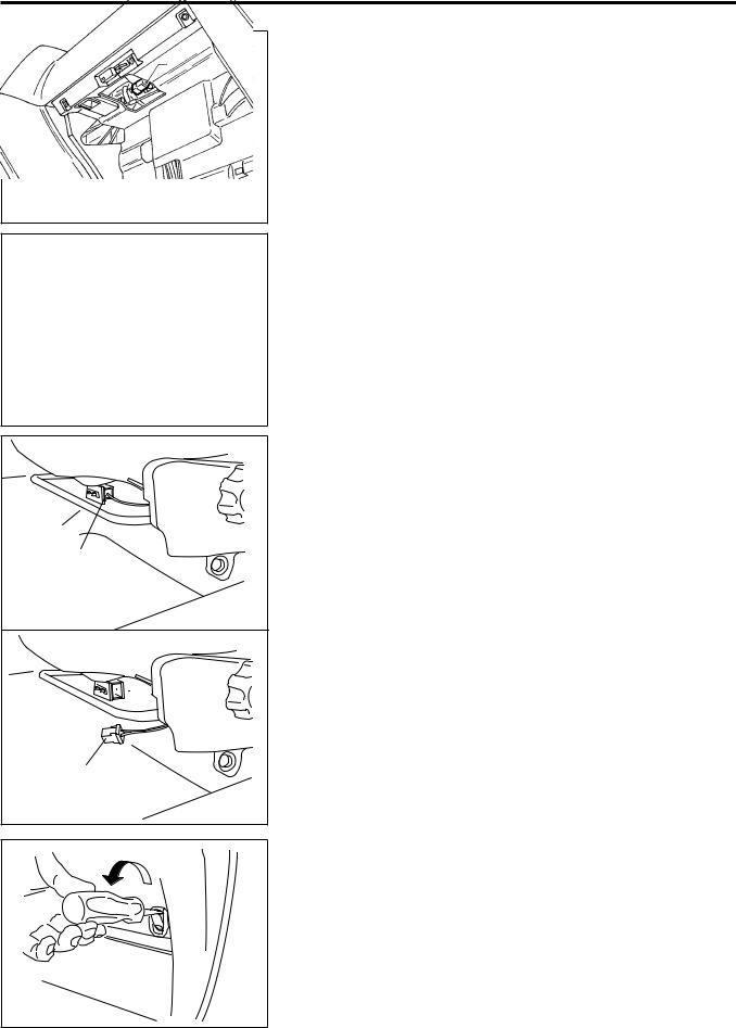
Removal Ð Side Air Bag Module
CAUTION:
●Before servicing SRS, turn the ignition switch ``OFF'', disconnect both battery cables and wait at least 3 min-
utes.
1.Slide the front seat all the way forward.
2.Disconnect side air bag module connector under the seat.
3.Remove screw securing the front seat convenience hook.
● When using a clip removal tool to remove the seat back finisher, take care not to damage the air bag harness.
4.Remove the seat back board.
RS-17
SUPPLEMENTAL RESTRAINT SYSTEM (SRS)
Inner cloth
6.1 - 7.7 N´m
.
(0.62 - 0.79 kg-m,
54 - 68 in-lb)
NRS065
Removal Ð Side Air Bag Module (Cont'd)
5.Pull up the seat back trim.
6.Remove the bolts securing the inner cloth with seat back frame.
Then pull up the inner cloth.
7.Remove the seat back trim. Refer to ``Front Seat'' in BT section for details.
.
6.1 - 7.7 N´m
(0.62 - 0.79 kg-m,
54 - 68 in-lb)
Side air bag module
NRS066
UP
SRS483
Air bag module
SBF814E
.
6.1 - 7.7 N´m
(0.62 - 0.79 kg-m,
54 - 68 in-lb)
Side air bag module
8.Remove the torx nuts coated with bonding agent from the side air bag module.
9.Remove side air bag connector. Side air bag module can then be removed.
CAUTION:
●Always place the air bag module with the stud bolts side facing down.
●Do not attempt to disassemble air bag module.
●The torx nuts are coated with bonding agent. Do not use old nuts after removal; replace with new coated nuts.
●Do not insert any foreign objects (screwdriver, etc.) into air bag module connector.
●Replace air bag module if it has been dropped or sustained an impact.
●Do not expose the air bag module to temperatures exceeding 90°C (194°F).
●Do not allow oil, grease or water to come in contact with the air bag module.
●After air bag inflates, all parts of front seat back (including front seat back frame) should be replaced.
Installation Ð Side Air Bag Module
1.Install side air bag module on seat back frame with new torx nuts coated with bonding agent.
NRS066
RS-18
Loading...