


NAVARA D40
Table of contents
 Loading...
GENERAL INFORMATION
SECTION
GI
CONTENTS
PRECAUTIONS .........................................................1
Precautions for Supplemental Restraint
System (SRS) ‘‘AIR BAG’’ (4WD models).............1
Precautions for Supplemental Restraint
System (SRS) ‘‘AIR BAG’’ (2WD models).............1
Precautions for NATS............................................2
General Precautions..............................................2
Precautions for Multiport Fuel Injection System
or ECCS Engine ....................................................4
Precautions for Three Way Catalyst
(If so equipped)......................................................4
Precautions for Engine Oils...................................4
Precautions for Fuel...............................................5
Precautions for Air Conditioning............................6
HOW TO USE THIS MANUAL..................................7
HOW TO READ WIRING DIAGRAMS......................9
Sample/Wiring Diagram - EXAMPL - ....................9
Description...........................................................11
HOW TO CHECK TERMINAL.................................18
How to Probe Connectors ...................................18
How to Check Enlarged Contact Spring of
Terminal...............................................................19
Waterproof Connector Inspection........................20
Terminal Lock Inspection.....................................20
HOW TO PERFORM EFFICIENT DIAGNOSIS
FOR AN ELECTRICAL INCIDENT .........................21
Work Flow............................................................21
HOW TO PERFORM EFFICIENT DIAGNOSIS......22
Incident Simulation Tests.....................................22
Circuit Inspection .................................................25
HOW TO FOLLOW FLOW CHART IN
TROUBLE DIAGNOSES .........................................31
How to Follow This Flow Chart ...........................32
CONSULT CHECKING SYSTEM............................34
Function and System Application........................34
Lithium Battery Replacement...............................34
Checking Equipment............................................35
Loading Procedure...............................................36
CONSULT Data Link Connector (DLC) Circuit ...36
IDENTIFICATION INFORMATION..........................37
Model Variation....................................................37
Identification Number...........................................40
Dimensions ..........................................................44
Wheels and Tires.................................................46
LIFTING POINTS AND TOW TRUCK TOWING.....47
Pantograph Jack..................................................47
Screw Jack...........................................................48
Garage Jack and Safety Stand ...........................49
2-pole Lift.............................................................50
Tow Truck Towing ...............................................51
Towing Point........................................................53
TIGHTENING TORQUE OF STANDARD BOLTS..54
SAE J1930 TERMINOLOGY LIST..........................55
SAE J1930 Terminology List...............................55
GI
Observe the following precautions to ensure safe and
proper servicing. These precautions are not described in
each individual section.
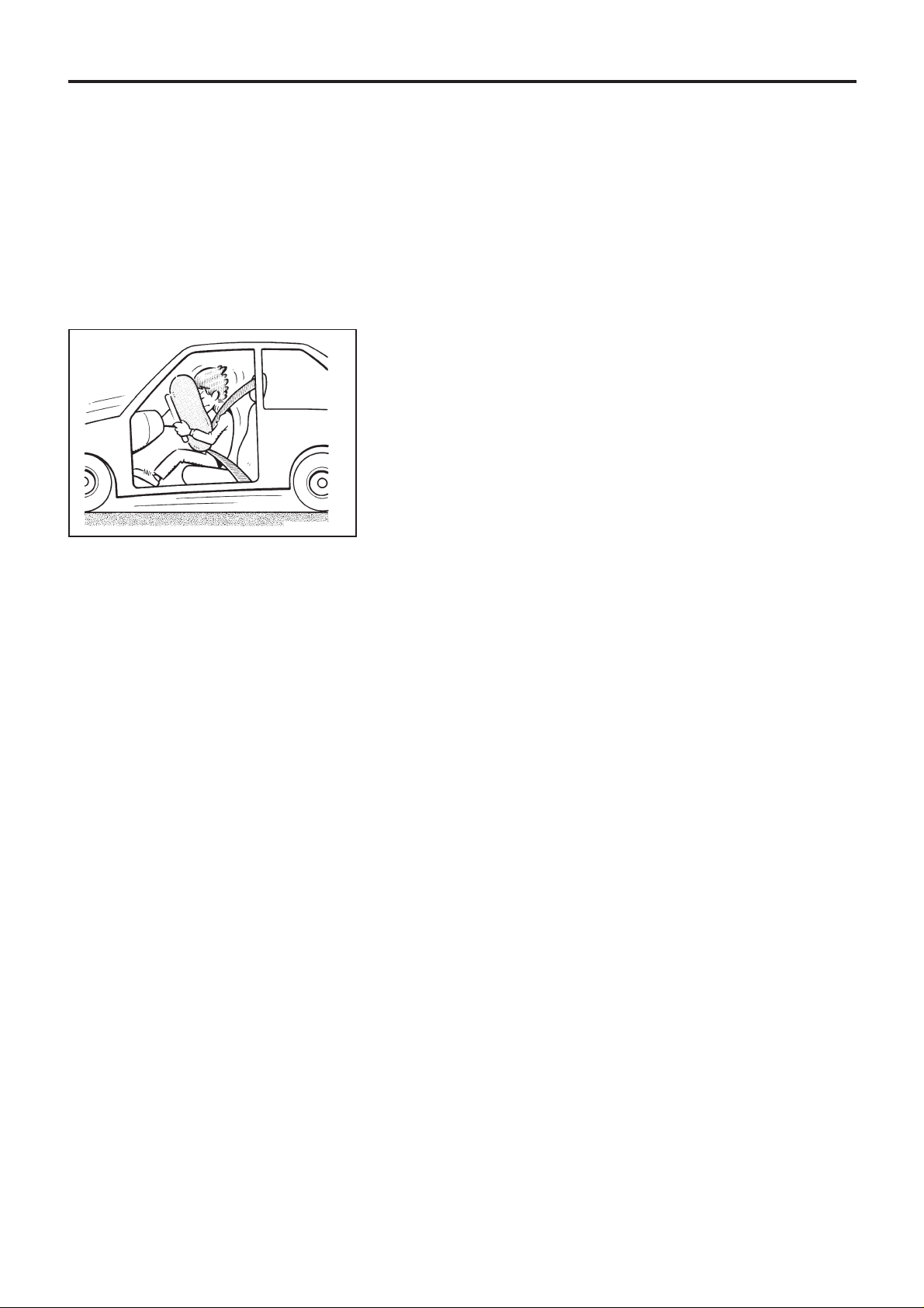
Precautions for Supplemental Restraint
System (SRS) ‘‘AIR BAG’’ (4WD models)
The Supplemental RestraintSystem ‘‘AIR BAG’’, used along with
a seat belt, helps to reduce the risk or severity of injury to the
driver in a frontal collision. The Supplemental Restraint System
consists of an air bag module (located in the center of the steer-
ing wheel), a diagnosissensor unit, warning lamp,wiring harness
and spiral cable. Information necessary to service the system
safely is included in the RS section of this Service Manual.
WARNING:
● To avoid rendering the SRS inoperative, which could
increase the risk of personal injury or death in the event
of a collision which would result in air bag inflation, all
maintenance must be performed by an authorized
NISSAN dealer.
● Improper maintenance, including incorrect removal and
installation of the SRS, can lead to personal injury
caused by unintentional activation of the system.
● Do not use electrical test equipment on any circuit
related to the SRS unless instructed to in this Service
Manual. SRS wiring harnesses are covered with yellow
insulation either just before the harness connectors or
for the complete harness, for easy identification.
Precautions for Supplemental Restraint
System (SRS) ‘‘AIR BAG’’ (2WD models)
The Supplemental RestraintSystem ‘‘AIR BAG’’, used along with
a seat belt, helps to reduce the risk or severity of injury to the
driver in a frontal collision. The Supplemental Restraint System
consists of an air bag module (located in the center of the steer-
ing wheel), a diagnosis sensor unit, warning lamp and spiral
cable. Information necessary to service the system safely is
included in the RS section of this Service Manual.
WARNING:
● To avoid rendering the SRS inoperative, which could
increase the risk of personal injury or death in the event
of a collision which would result in air bag inflation, all
maintenance must be performed by an authorized
NISSAN dealer.
● Improper maintenance, including incorrect removal and
installation of the SRS, can lead to personal injury
caused by unintentional activation of the system.
● Do not use electrical test equipment on any circuit
related to the SRS.
SGI646
PRECAUTIONS
GI-1
Precautions for NATS
NATS (Nissan Anti-Theft System)
NATS will immobilize the engine if someone tries to start it with-
out the registered key of NATS.
All of the originally supplied ignition key IDs have been NATS
registered.
The NATS security indicator is located on the instrument panel.
The indicator blinks when the ignition switch is in ‘‘OFF’’ or
‘‘ACC’’ position. Therefore, NATS warns outsiders that the
vehicle is equipped with the anti-theft system.
● Gasoline engine:
When NATS detects trouble, the malfunction indicator lamp
(MIL) blinks.
This blinking indicates that the anti-theft is not functioning, so
prompt service is required.
● Diesel engine:
When NATS detects trouble while engine is running or igni-
tion switch in ‘‘ON’’ position, the NATS security indicator
comes on.
This indicates that the anti-theft is not functioning, so prompt
service is required.
● When servicing NATS (trouble diagnoses, system initialisa-
tion and additional registration of other NATS ignition key
IDs), CONSULT hardware and CONSULT NATS software is
necessary.
Regarding the procedures of NATS initialisation and NATS
ignition key ID registration, refer to CONSULT operation
manual, NATS.
Therefore, CONSULT NATS software (program card and
operation manual) must be kept strictly confidential to main-
tain the integrity of the anti-theft function.
● When servicing NATS (trouble diagnoses, system initialisa-
tion and additional registration of other NATS ignition key
IDs), it may be necessary to re-register original key identifi-
cation. Therefore, be sure to receive all keys from vehicle
owner.
A maximum of four key IDs can be registered into NATS.
General Precautions
● Do not operate the engine for an extended period of time
without proper exhaust ventilation.
Keep the work area well ventilated and free of any inflam-
mable materials. Special care should be taken when han-
dling any inflammable or poisonous materials, such as
gasoline, refrigerant gas, etc. When working in a pit or other
enclosed area, be sure to properly ventilate the area before
working with hazardous materials.
Do not smoke while working on the vehicle.
SGI916
SGI285
PRECAUTIONS
GI-2
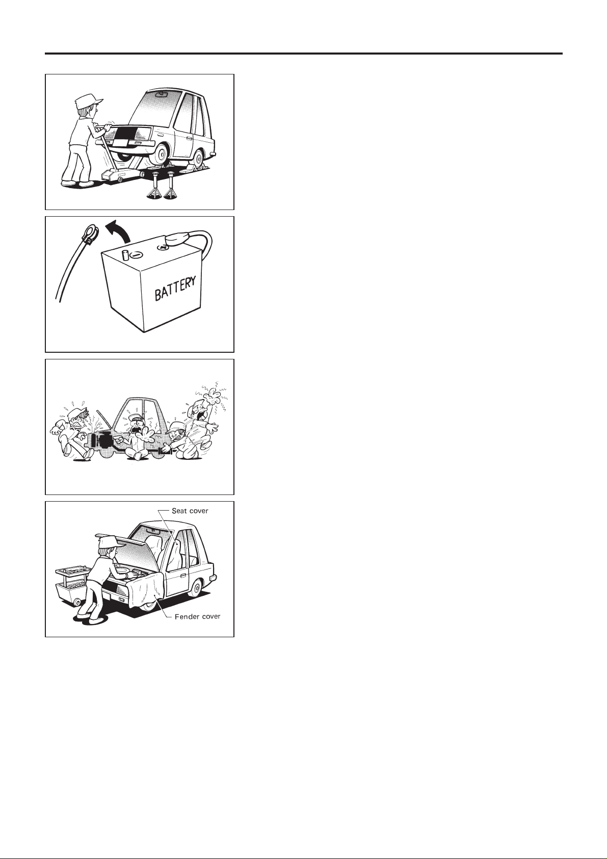
● Before jacking up the vehicle, apply wheel chocks or other
tire blocks to the wheels to prevent the vehicle from moving.
After jacking up the vehicle, support the vehicle weight with
safety stands at the points designated for proper lifting before
working on the vehicle.
These operations should be done on a level surface.
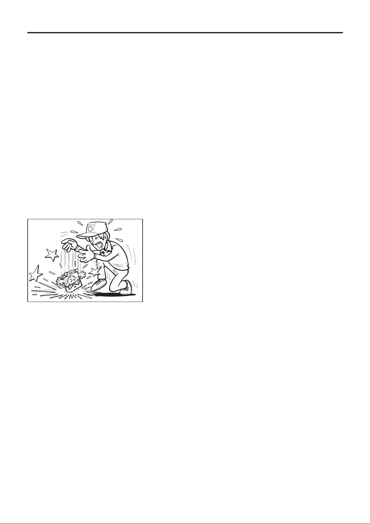
● When removing a heavy component such as the engine or
transaxle/transmission, be careful not to lose your balance
and drop them. Also, do not allow them to strike adjacent
parts, especially the brake tubes and master cylinder.
● Before starting repairs which do not require battery power:
Turn off ignition switch.
Disconnect the negative battery terminal.
● To prevent serious burns:
Avoid contact with hot metal parts.
Do not remove the radiator cap when the engine is hot.
● Before servicing the vehicle:
Protect fenders, upholstery and carpeting with appropriate
covers.
Take caution that keys, buckles or buttons do not scratch
paint.
● Clean all disassembled parts in the designated liquid or sol-
vent prior to inspection or assembly.
● Replace oil seals, gaskets, packings, O-rings, locking
washers, cotter pins, self-locking nuts, etc. with new ones.
● Replace inner and outer races of tapered roller bearings and
needle bearings as a set.
● Arrange the disassembled parts in accordance with their
assembled locations and sequence.
● Do not touch the terminals of electrical components which
use microcomputers (such as ECMs).
Static electricity may damage internal electronic compo-
nents.
SGI231
SEF289H
SGI233
SGI234
PRECAUTIONS
General Precautions (Cont’d)
GI-3
● After disconnecting vacuum or air hoses, attach a tag to
indicate the proper connection.
● Use only the fluids and lubricants specified in this manual.
● Use approved bonding agent, sealants or their equivalents
when required.
● Use tools and recommended special tools where specified
for safe and efficient service repairs.
● When repairing the fuel, oil, water, vacuum or exhaust
systems, check all affected lines for leaks.
● Dispose of drained oil or the solvent used for cleaning parts
in an appropriate manner.
WARNING:
To prevent ECM from storing the diagnostic trouble codes,
do not carelessly disconnect the harness connectors which
are related to the ECCS system and TCM (Transmission
Control Module) system. The connectors should be discon-
nected only when working according to the WORK FLOW of
TROUBLE DIAGNOSES in EC section.
Precautions for Multiport Fuel Injection
System or ECCS Engine
● Before connecting or disconnecting any harness connector
for the multiport fuel injection system or ECM (Engine Con-
trol Module):
Turn ignition switch to ‘‘OFF’’ position.
Disconnect negative battery terminal.
Otherwise, there may be damage to ECM.
●
Before disconnecting pressurized fuel line from fuel pump to
injectors, be sure to release fuel pressure.
● Be careful not to jar components such as ECM and mass air
flow sensor.
Precautions for Three Way Catalyst
(If so equipped)
If a large amount of unburned fuel flows into the catalyst, the
catalyst temperature will be excessively high. To prevent this,
follow the instructions below:
● Use unleaded gasoline only. Leaded gasoline will seriously
damage the three way catalyst.
● When checking for ignition spark or measuring engine
compression, make tests quickly and only when necessary.
● Do not run engine when the fuel tank level is low, otherwise
the engine may misfire causing damage to the catalyst.
Do not place the vehicle on flammable material. Keep flammable
material off the exhaust pipe and the three way catalyst.
Precautions for Engine Oils
Prolonged and repeated contact with used engine oil may cause
skin cancer. Try to avoid direct skin contact with used oil.
SGI787
PRECAUTIONS
General Precautions (Cont’d)
GI-4

If skin contact is made, wash thoroughly with soap or hand
cleaner as soon as possible.
HEALTH PROTECTION PRECAUTIONS
● Avoid prolonged and repeated contact with oils, particularly
used engine oils.
● Wear protective clothing, including impervious gloves where
practicable.
● Do not put oily rags in pockets.
● Avoid contaminating clothes, particularly underpants, with oil.
● Heavily soiled clothing and oil-impregnated footwear should
not be worn. Overalls must be cleaned regularly.
● First Aid treatment should be obtained immediately for open
cuts and wounds.
● Use barrier creams, applying them before each work period,
to help the removal of oil from the skin.
● Wash with soap and water to ensure all oil is removed (skin
cleansers and nail brushes will help). Preparations contain-
ing lanolin replace the natural skin oils which have been
removed.
● Do not use gasoline, kerosine, diesel fuel, gas oil, thinners
or solvents for cleaning skin.
● If skin disorders develop, obtain medical advice without
delay.
● Where practicable, degrease components prior to handling.
● Where there is a risk of eye contact, eye protection should
be worn, for example, chemical goggles or face shields; in
addition an eye wash facility should be provided.
ENVIRONMENTAL PROTECTION PRECAUTIONS
Burning used engine oil in small space heaters or boilers can be
recommended only for units of approved design. The heating
system must meet the requirements of HM Inspectorate of Pol-
lution for small burners of less than 0.4 MW. If in doubt check
with the appropriate local authority and/or manufacturer of the
approved appliance.
Dispose of used oil and used oil filters through authorized waste
disposal contractors to licensed waste disposal sites, or to the
waste oil reclamation trade. If in doubt, contact the local author-
ity for advice on disposal facilities.
It is illegal to pour used oil on to the ground, down sewers or
drains, or into water courses.
The regulations concerning the pollution of the environment
will vary from country to country.
Precautions for Fuel
GASOLINE ENGINE:
Three way catalyst equipped models ... unleaded gasoline of at
least 91 octane (RON)
CAUTION:
Do not use leaded gasoline. Using leaded gasoline will dam-
age the three way catalyst.
Except for the above models ... unleaded or leaded gasoline of
above 88 octane (RON)
Use unleaded fuel if instructed on the fuel filler lid.
PRECAUTIONS
Precautions for Engine Oils (Cont’d)
GI-5

DIESEL ENGINE*:
For Europe: diesel fuel of above 50 cetane
* If two types of diesel fuel are available, use summer or win-
ter fuel properly according to the following temperature con-
ditions.
● Above −7°C (20°F) ... Summer type diesel fuel.
● Below −7°C (20°F) ... Winter type diesel fuel.
CAUTION:
● Do not use home heating oil, gasoline, or other alternate
fuels in your diesel engine. The use of those can cause
engine damage.
● Do not use summer fuel at temperature below −7°C
(20°F). The cold temperature will cause wax to form in
the fuel. As a result, it may prevent the engine from run-
ning smoothly.
● Do not add gasoline or other alternate fuels to diesel
fuel.
Precautions for Air Conditioning
Use an approved refrigerant recovery unit any time the air con-
ditioning system must be discharged. Refer to HA section
(‘‘HFC-134a (R-134a) Service Procedure’’, ‘‘SERVICE PRO-
CEDURES’’) for specific instructions.
PRECAUTIONS
Precautions for Fuel (Cont’d)
GI-6
● ALPHABETICAL INDEX is provided at the end of this manual so that you can rapidly find the item and
page you are searching for.
● A QUICK REFERENCE INDEX, a black tab (e.g. ) is provided on the first page. You can quickly
find the first page of each section by mating it to the section’s black tab.
● THE CONTENTS are listed on the first page of each section.
● THE TITLE is indicated on the upper portion of each page and shows the part or system.
● THE PAGE NUMBER of each section consists of two letters which designate the particular section and
a number (e.g. ‘‘BR-5’’).
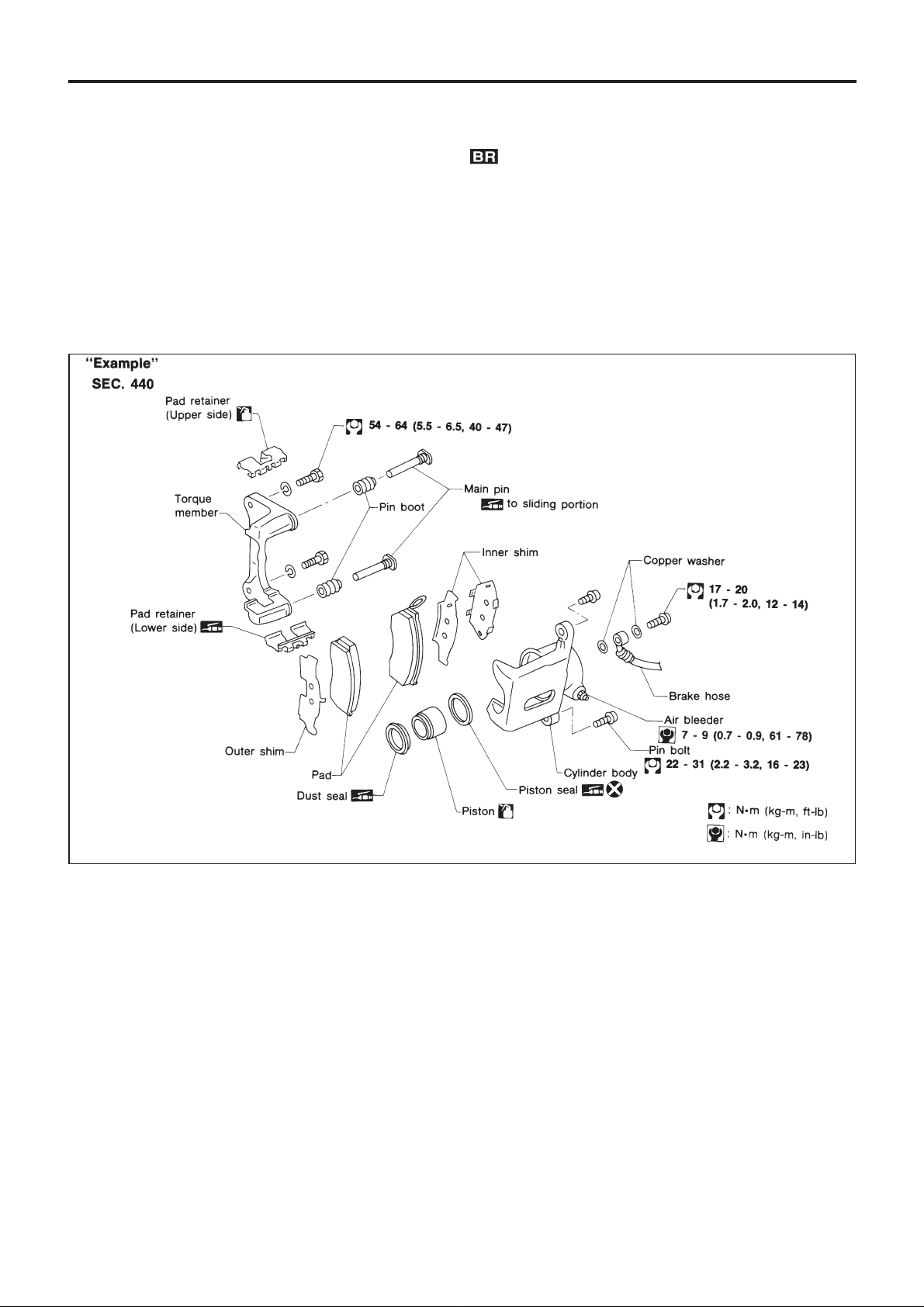
● THE LARGE ILLUSTRATIONS are exploded views (See below) and contain tightening torques, lubri-
cation points, section number of the PARTS CATALOG (e.g. SEC. 440) and other information neces-
sary to perform repairs.
The illustrations should be used in reference to service matters only. When ordering parts, refer to the
appropriate PARTS CATALOG.
● THE SMALL ILLUSTRATIONS show the important steps such as inspection, use of special tools,
knacks of work and hidden or tricky steps which are not shown in the previous large illustrations.
Assembly, inspection and adjustment procedures for the complicated units such as the automatic tran-
saxle or transmission, etc. are presented in a step-by-step format where necessary.
SBR364AC
HOW TO USE THIS MANUAL
GI-7

● The following SYMBOLS AND ABBREVIATIONS are used:
, : Tightening torque
: Should be lubricated with grease.
Unless otherwise indicated, use
recommended multi-purpose
grease.
: Should be lubricated with oil.
: Sealing point
: Checking point
: Always replace after every disas-
sembly.
V
P
: Apply petroleum jelly.
: Apply ATF.
. : Select with proper thickness.
> : Adjustment is required.
SDS : Service Data and Specifications
LH, RH : Left-Hand, Right-Hand
FR, RR : Front, Rear
M/T : Manual Transaxle/Transmission
A/T : Automatic Transaxle/Transmission
,
4WD : 4-Wheel Drive
2WD : 2-Wheel Drive
A/C : Air Conditioner
P/S : Power Steering
SST : Special Service Tools
SAE : Society of Automotive Engineers,
Inc.
ATF : Automatic Transmission Fluid
D
1
: Drive range 1st gear
D
2
: Drive range 2nd gear
D
3
: Drive range 3rd gear
D
4
: Drive range 4th gear
OD : Overdrive
2
2
: 2nd range 2nd gear
2
1
: 2nd range 1st gear
1
2
: 1st range 2nd gear
1
1
: 1st range 1st gear
● The UNITS given in this manual are primarily expressed as the SI UNIT (International System of Unit),
and alternatively expressed in the metric system and in the yard/pound system.
‘‘Example’’
Tightening torque:
59 - 78 N·m (6.0 - 8.0 kg-m, 43 - 58 ft-lb)
● TROUBLE DIAGNOSES are included in sections dealing with complicated components.
● SERVICE DATA AND SPECIFICATIONS are contained at the end of each section for quick reference
of data.
● The captions WARNING and CAUTION warn you of steps that must be followed to prevent personal
injury and/or damage to some part of the vehicle.
WARNING indicates the possibility of personal injury if instructions are not followed.
CAUTION indicates the possibility of component damage if instructions are not followed.
BOLD TYPED STATEMENTS except WARNING and CAUTION give you helpful information.
HOW TO USE THIS MANUAL
GI-8
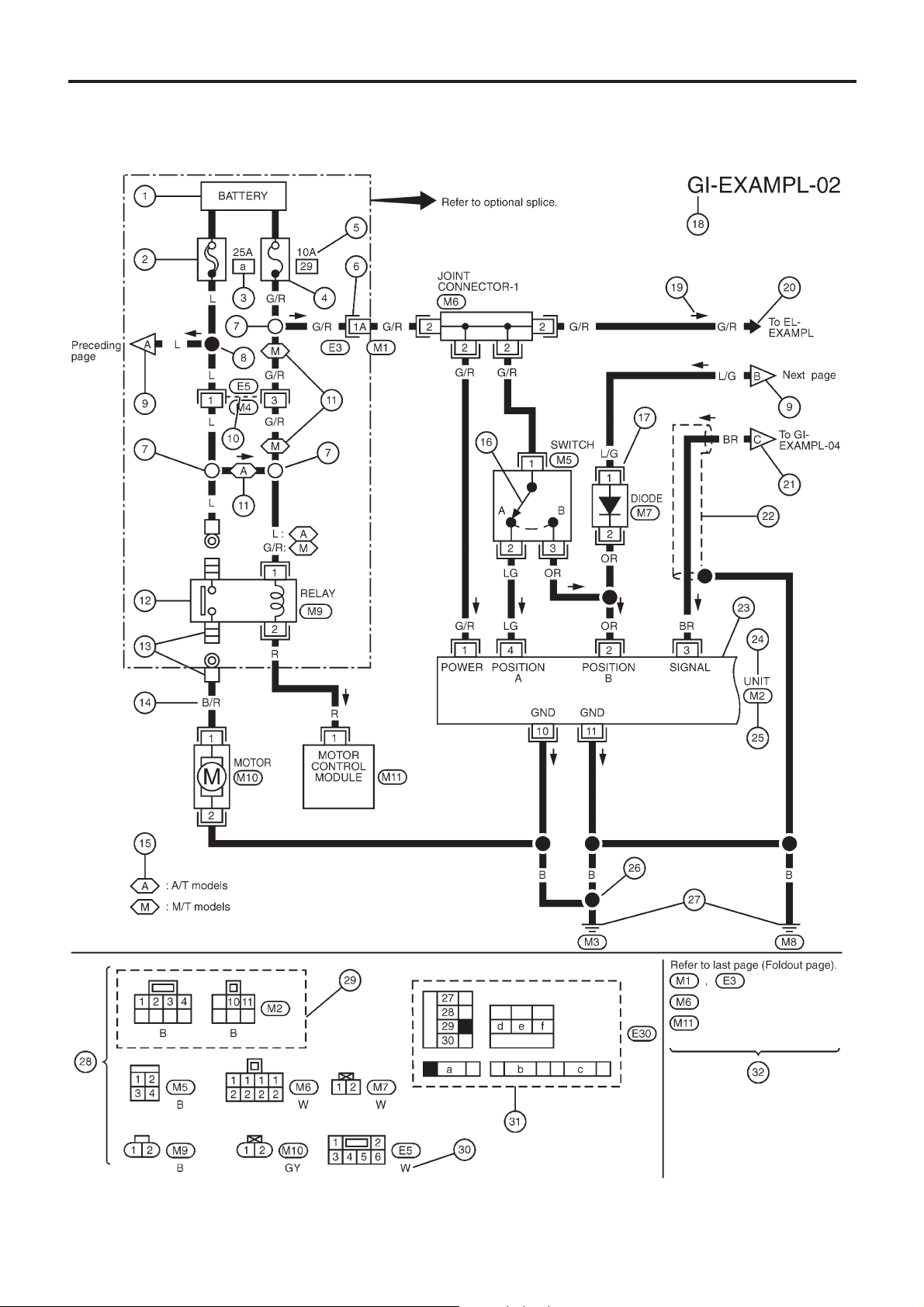
Sample/Wiring Diagram — EXAMPL —
● For Description, refer to GI-11.
YGI001
HOW TO READ WIRING DIAGRAMS
GI-9
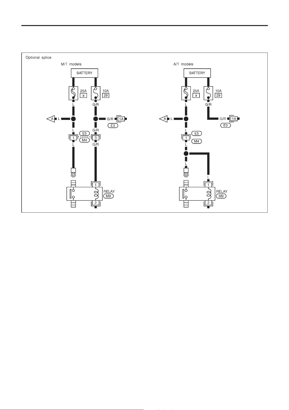
OPTIONAL SPLICE
SGI942
HOW TO READ WIRING DIAGRAMS
Sample/Wiring Diagram — EXAMPL —
(Cont’d)
GI-10
Description
Number Item Description
V
1
Power condition
● This shows the condition when the system receives battery positive voltage (can
be operated).
V
2
Fusible link
● The double line shows that this is a fusible link.
● The open circle shows current flow in, and the shaded circle shows current flow
out.
V
3
Fusible link/fuse location
● This shows the location of the fusible link or fuse in the fusible link or fuse box.
For arrangement, refer to EL section (‘‘POWER SUPPLY ROUTING’’).
V
4
Fuse
● The single line shows that this is a fuse.
● The open circle shows current flow in, and the shaded circle shows current flow
out.
V
5
Current rating ● This shows the current rating of the fusible link or fuse.
V
6
Connectors
● This shows that connector
E3
is female and connector
M1
is male.
● The G/R wire is located in the 1A terminal of both connectors.
● Terminal number with an alphabet (1A, 5B, etc.) indicates that the connector is
SMJ connector. Refer to GI-17.
V
7
Optional splice ● The open circle shows that the splice is optional depending on vehicle application.
V
8
Splice ● The shaded circle shows that the splice is always on the vehicle.
V
9
Page crossing
● This arrow shows that the circuit continues to an adjacent page.
● The A will match with the A on the preceding or next page.
V
10
Common connector
● The dotted lines between terminals show that these terminals are part of the same
connector.
V
11
Option abbreviation ● This shows that the circuit is optional depending on vehicle application.
V
12
Relay
● This shows an internal representation of the relay. For details, refer to EL section
(‘‘STANDARDIZED RELAY’’).
V
13
Connectors
● This shows that the connector is connected to the body or a terminal with bolt or
nut.
V
14
Wire color
● This shows a code for the color of the wire.
B = Black BR = Brown
W = White OR = Orange
R = Red P = Pink
G = Green PU = Purple
L = Blue GY = Gray
Y = Yellow SB = Sky Blue
LG = Light Green CH = Dark Brown
DG = Dark Green
When the wire color is striped, the base color is given first, followed by the stripe
color as shown below:
Example: L/W = Blue with White Stripe
V
15
Option description ● This shows a description of the option abbreviation used on the page.
V
16
Switch
● This shows that continuity exists between terminals 1 and 2 when the switch is in
the A position. Continuity exists between terminals 1 and 3 when the switch is in
the B position.
V
17
Assembly parts
● Connector terminal in component shows that it is a harness incorporated assem-
bly.
V
18
Cell code
● This identifies each page of the wiring diagram by section, system and wiring dia-
gram page number.
HOW TO READ WIRING DIAGRAMS
GI-11

Number Item Description
V
19
Current flow arrow
● Arrow indicates electric current flow, especially where the direction of standard
flow (vertically downward or horizontally from left to right) is difficult to follow.
● A double arrow ‘‘b
—
c’’ shows that current can flow in either direction depending
on circuit operation.
V
20
System branch
● This shows that the system branches to another system identified by cell code
(section and system).
V
21
Page crossing
● This arrow shows that the circuit continues to another page identified by cell code.
● The C will match with the C on another page within the system other than the next
or preceding pages.
V
22
Shielded line ● The line enclosed by broken line circle shows shield wire.
V
23
Component box in wave
line
● This shows that another part of the component is also shown on another page
(indicated by wave line) within the system.
V
24
Component name ● This shows the name of a component.
V
25
Connector number
● This shows the connector number.
● The letter shows which harness the connector is located in.
Example: M: main harness. For detail and to locate the connector, refer to EL sec-
tion (‘‘Main Harness’’, ‘‘HARNESS LAYOUT’’). A coordinate grid is included for
complex harnesses to aid in locating connectors.
V
26
Ground (GND)
● The line spliced and grounded under wire color shows that ground line is spliced
at the grounded connector.
V
27
Ground (GND) ● This shows the ground connection.
V
28
Connector views
● This area shows the connector faces of the components in the wiring diagram on
the page.
V
29
Common component
● Connectors enclosed in broken line show that these connectors belong to the
same component.
V
30
Connector color
● This shows a code for the color of the connector. For code meaning, refer to wire
color codes, Number
V
14
of this chart.
V
31
Fusible link and fuse box
● This shows the arrangement of fusible link(s) and fuse(s), used for connector
views of ‘‘POWER SUPPLY ROUTING’’ in EL section.
The open square shows current flow in, and the shaded square shows current
flow out.
V
32
Reference area
● This shows that more information on the Super Multiple Junction (SMJ) and Joint
Connectors (J/C) exists on the foldout page. Refer to GI-17 for details.
HOW TO READ WIRING DIAGRAMS
Description (Cont’d)
GI-12
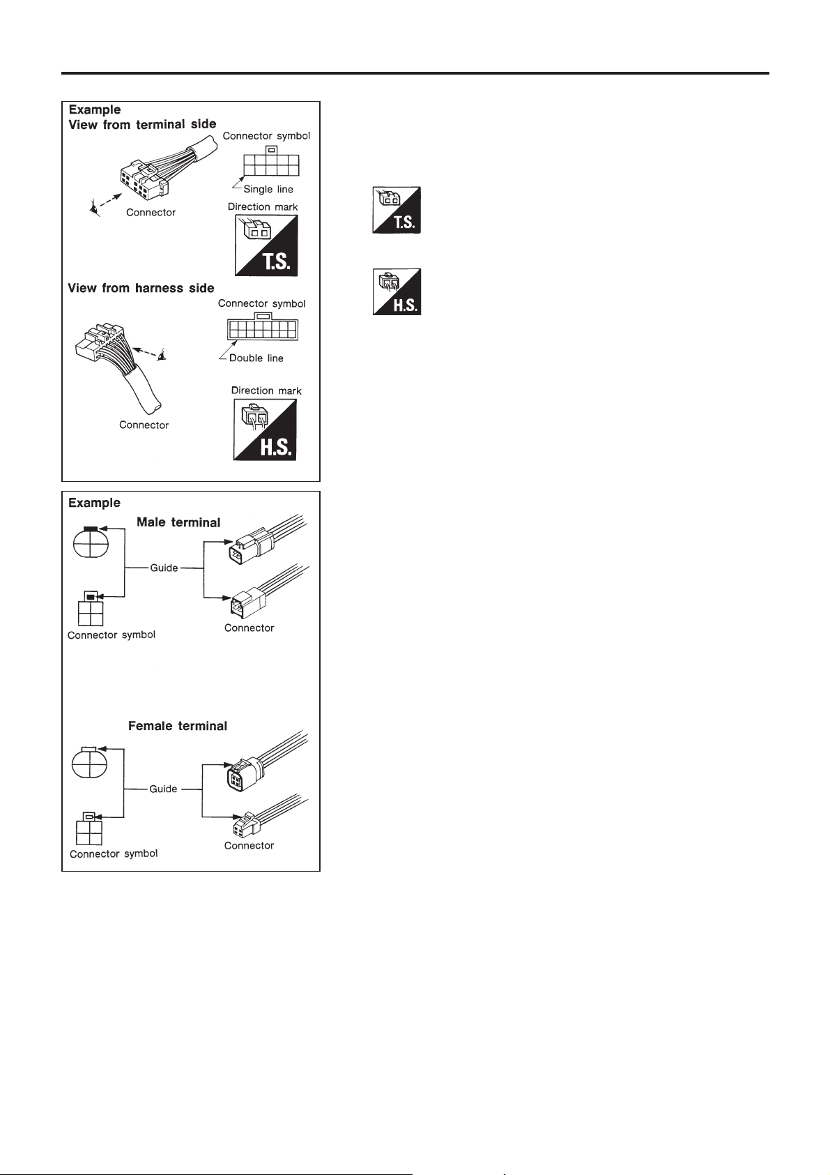
CONNECTOR SYMBOLS
Most of connector symbols in wiring diagrams are shown from
the terminal side.
● Connector symbols shown from the terminal side are
enclosed by a single line and followed by the direction mark
.
● Connector symbols shown from the harness side are
enclosed by a double line and followed by the direction mark
.
● Male and female terminals
Connector guides for male terminals are shown in black and
female terminals in white in wiring diagrams.
SGI364
SGI363
HOW TO READ WIRING DIAGRAMS
Description (Cont’d)
GI-13
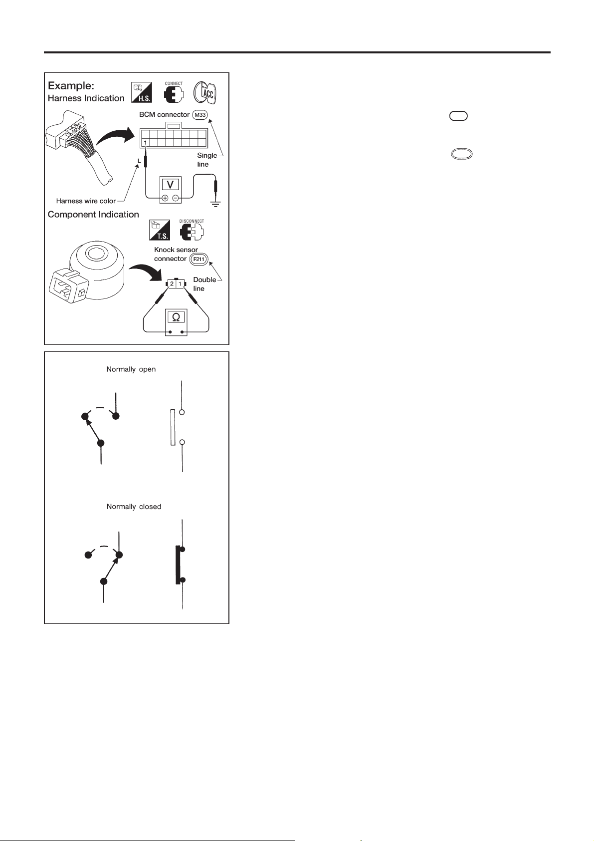
Harness indication
● Letter designations next to test meter probe indicate harness
(connector) wire color.
● Connector numbers in a single circle
M33
indicate harness
connectors.
Component indication
● Connector numbers in a double circle F211 indicate compo-
nent connectors.
SWITCH POSITIONS
Switches are shown in wiring diagrams as if the vehicle is in the
‘‘normal’’ condition.
A vehicle is in the ‘‘normal’’ condition when:
● ignition switch is ‘‘OFF’’,
● doors, hood and trunk lid/back door are closed,
● pedals are not depressed, and
● parking brake is released.
AGI070
SGI860
HOW TO READ WIRING DIAGRAMS
Description (Cont’d)
GI-14
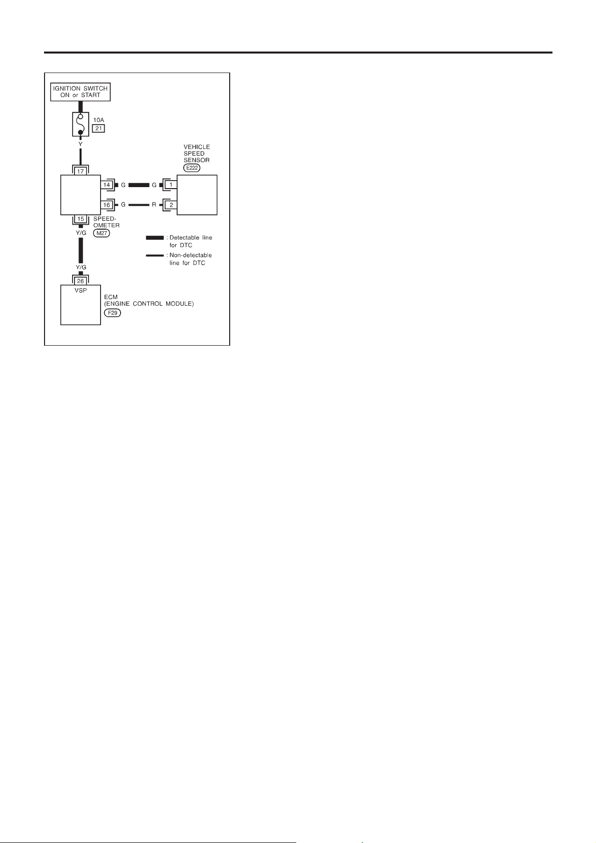
DETECTABLE LINES AND NON-DETECTABLE LINES
In some wiring diagrams, two kinds of lines, representing wires,
with different weight are used.
● A line with regular weight (wider line) represents a ‘‘detect-
able line for DTC (Diagnostic Trouble Code)’’. A ‘‘detectable
line for DTC’’ is a circuit in which ECM (Engine Control Mod-
ule) can detect its malfunctions with the on board diagnostic
system.
● A line with less weight (thinner line) represents a ‘‘non-de-
tectable line for DTC’’. A ‘‘non-detectable line for DTC’’ is a
circuit in which ECM cannot detect its malfunctions with the
on-board diagnostic system.
SGI862-A
HOW TO READ WIRING DIAGRAMS
Description (Cont’d)
GI-15
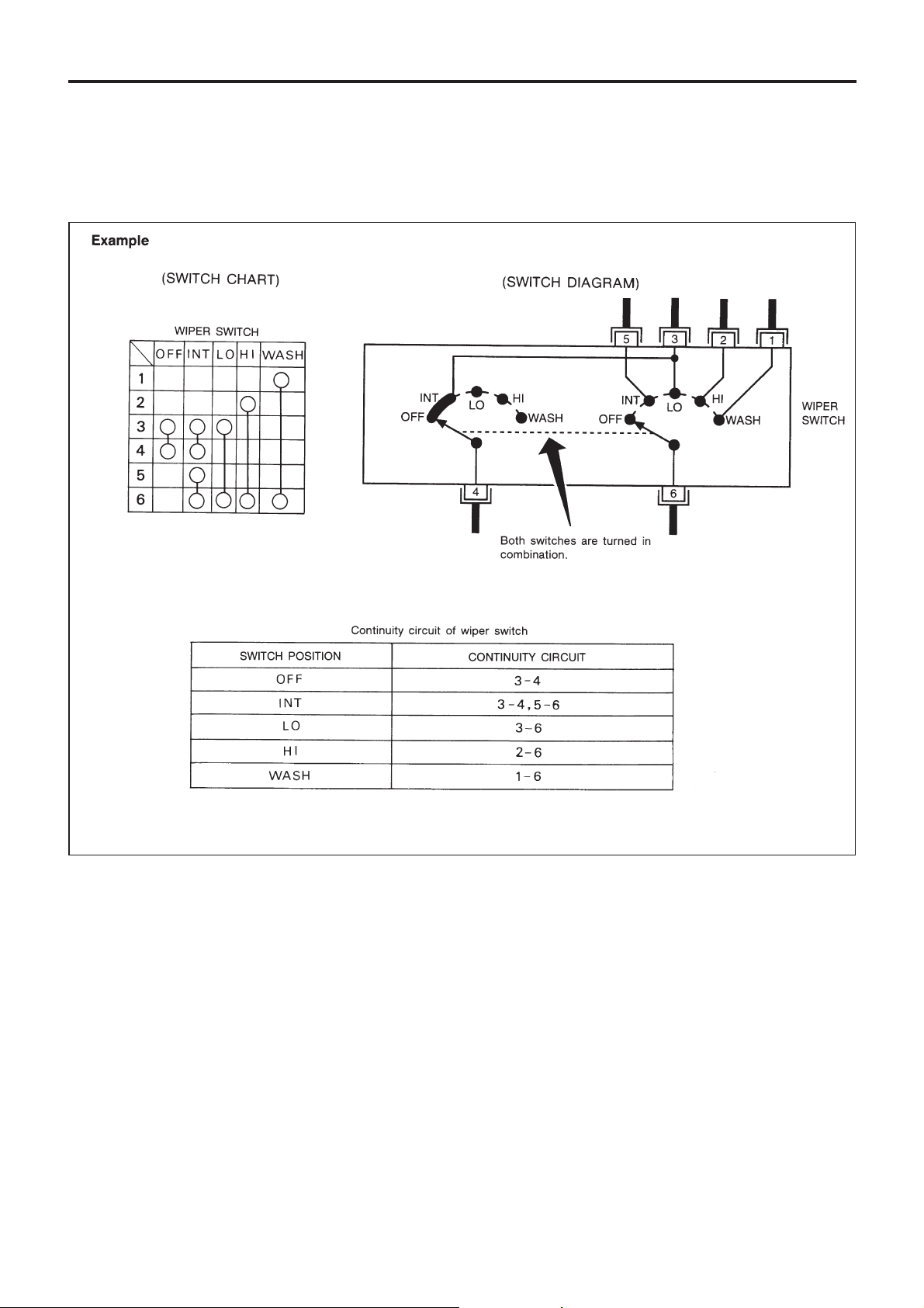
MULTIPLE SWITCH
The continuity of multiple switch is described in two ways as
shown below.
● The switch chart is used in schematic diagrams.
● The switch diagram is used in wiring diagrams.
SGI875
HOW TO READ WIRING DIAGRAMS
Description (Cont’d)
GI-16
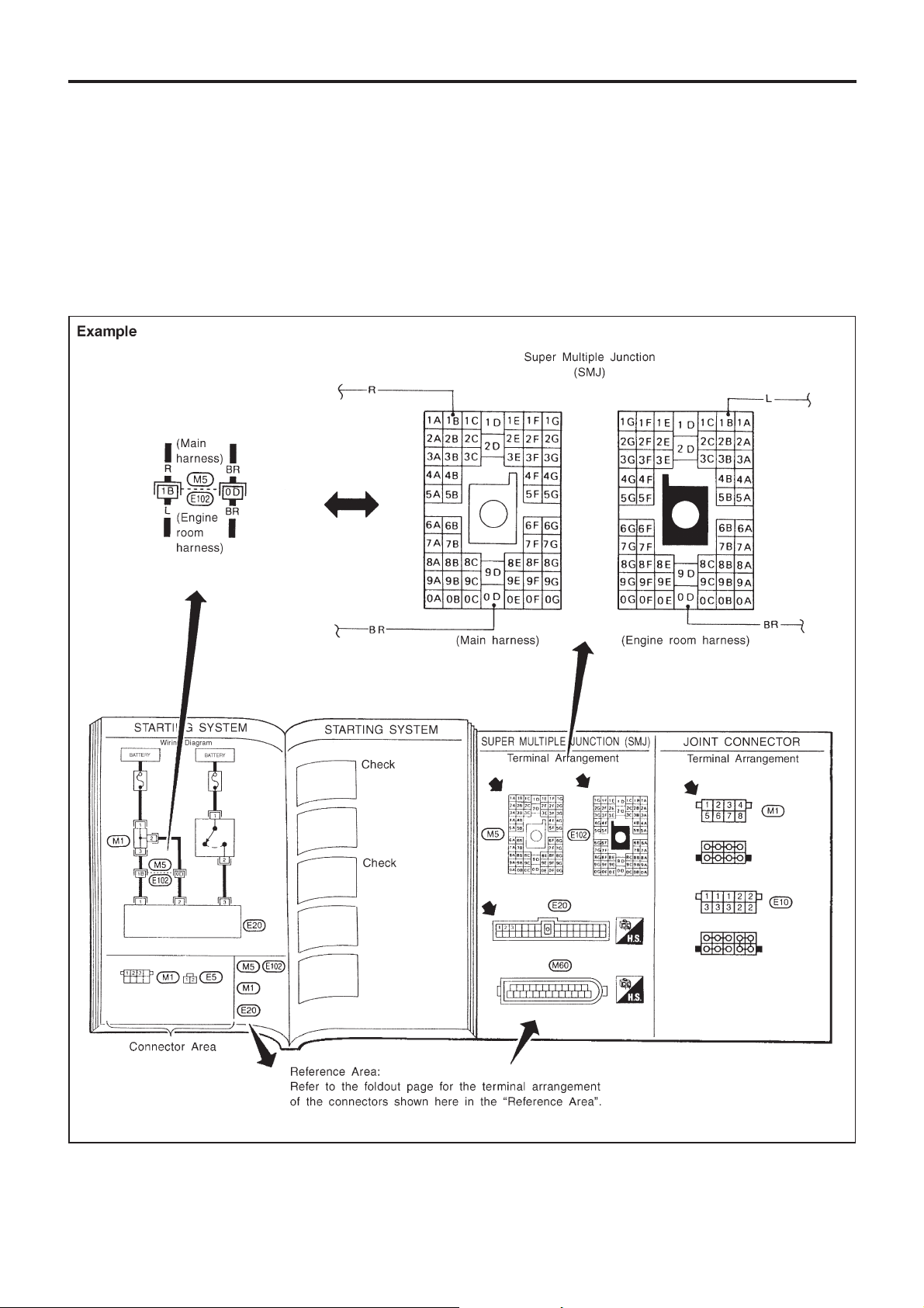
FOLDOUT PAGE
The foldout page should be opened when reading wiring diagram.
Super multiple junction (SMJ)
In wiring diagram,connectors consisting ofterminals having terminalnumbers with analphabet (1B, 0D, etc.)
are SMJ connectors.
If connector numbers are shown in Reference Area, these connector symbols are not shown in Connector
Area. For terminal arrangement of these connectors, refer to the foldout page at the end of this manual.
Joint connector
Joint connector symbols are shown in Connector Area in the wiring diagram concerned. Foldout page also
carries inside wiring layout together with such joint connector symbols.
SGI943
HOW TO READ WIRING DIAGRAMS
Description (Cont’d)
GI-17
Loading...