


Primera
Table of contents
 Loading...
ENGINE CONTROL SYSTEM
CONTENTS
SR20DE
TROUBLE DIAGNOSIS — INDEX..................................6
Alphabetical & P No. Index for DTC ...........................6
PRECAUTIONS .............................................................10
Supplemental Restraint System (SRS) ‘‘AIR
BAG’’ and ‘‘SEAT BELT PRE-TENSIONER’’............10
Precautions for On Board Diagnostic (OBD)
System of Engine and CVT.......................................10
Engine Fuel & Emission Control System..................11
Precautions................................................................12
Wiring Diagrams and Trouble Diagnosis...................13
PREPARATION .............................................................14
Special Service Tools................................................14
Commercial Service Tool ..........................................14
ENGINE AND EMISSION CONTROL OVERALL
SYSTEM.........................................................................15
Engine Control Component Parts Location...............15
Circuit Diagram..........................................................19
System Diagram........................................................20
Vacuum Hose Drawing..............................................21
System Chart.............................................................22
ENGINE AND EMISSION BASIC CONTROL...............23
Multiport Fuel Injection (MFI) System .......................23
Distributor Ignition (DI) System .................................25
Air Conditioning Cut Control......................................26
Fuel Cut Control (at no load & high engine
speed)........................................................................27
Evaporative Emission System...................................27
Positive Crankcase Ventilation..................................30
BASIC SERVICE PROCEDURE...................................31
Fuel Pressure Release..............................................31
Fuel Pressure Check.................................................31
Fuel Pressure Regulator Check................................32
Injector.......................................................................32
Idle Speed/Ignition Timing/Idle Mixture Ratio
Adjustment.................................................................34
Idle Air Volume Learning...........................................46
SECTION
ON BOARD DIAGNOSTIC SYSTEM
DESCRIPTION...............................................................48
Introduction................................................................48
Two Trip Detection Logic...........................................48
Emission-related Diagnostic Information...................49
Malfunction Indicator (MI)..........................................58
OBD System Operation Chart...................................63
CONSULT-II...............................................................68
Generic Scan Tool (GST)..........................................78
TROUBLE DIAGNOSIS — INTRODUCTION...............80
Introduction................................................................80
Work Flow..................................................................82
TROUBLE DIAGNOSIS — BASIC INSPECTION ........84
Basic Inspection.........................................................84
TROUBLE DIAGNOSIS — GENERAL
DESCRIPTION...............................................................93
DTC Inspection Priority Chart....................................93
Fail-safe Chart...........................................................94
Symptom Matrix Chart...............................................95
CONSULT-II Reference Value in Data Monitor
Mode..........................................................................99
Major Sensor Reference Graph in Data Monitor
Mode........................................................................101
ECM Terminals and Reference Value.....................104
TROUBLE DIAGNOSIS FOR INTERMITTENT
INCIDENT.....................................................................112
Description...............................................................112
Diagnostic Procedure ..............................................112
TROUBLE DIAGNOSIS FOR POWER SUPPLY........113
Main Power Supply and Ground Circuit..................113
DTC P0100 MASS AIR FLOW SENSOR (MAFS)......118
Component Description...........................................118
CONSULT-II Reference Value in Data Monitor
Mode........................................................................118
ECM Terminals and Reference Value.....................118
On Board Diagnosis Logic.......................................118
DTC Confirmation Procedure..................................119
Wiring Diagram........................................................120
EC
EC

CONTENTS
(Cont’d)
Diagnostic Procedure ..............................................121
Component Inspection.............................................124
DTC P0110 INTAKE AIR TEMPERATURE
SENSOR ......................................................................125
Component Description...........................................125
On Board Diagnosis Logic.......................................125
DTC Confirmation Procedure..................................125
Wiring Diagram........................................................126
Diagnostic Procedure ..............................................127
Component Inspection.............................................128
DTC P0115 ENGINE COOLANT TEMPERATURE
SENSOR (ECTS) (CIRCUIT).......................................129
Component Description...........................................129
CONSULT-II Reference Value in Data Monitor
Mode........................................................................129
On Board Diagnosis Logic.......................................129
DTC Confirmation Procedure..................................130
Wiring Diagram........................................................131
Diagnostic Procedure ..............................................132
Component Inspection.............................................133
DTC P0120 THROTTLE POSITION SENSOR ...........134
Component Description...........................................134
CONSULT-II Reference Value in Data Monitor
Mode........................................................................134
ECM Terminals and Reference Value.....................135
On Board Diagnosis Logic.......................................135
DTC Confirmation Procedure..................................135
Wiring Diagram........................................................137
Diagnostic Procedure ..............................................138
Component Inspection.............................................139
DTC P0130 FRONT HEATED OXYGEN SENSOR
(FRONT HO2S) (CIRCUIT)..........................................141
Component Description...........................................141
CONSULT-II Reference Value in Data Monitor
Mode........................................................................141
ECM Terminals and Reference Value.....................141
On Board Diagnosis Logic.......................................142
DTC Confirmation Procedure..................................142
Overall Function Check...........................................143
Wiring Diagram........................................................144
Diagnostic Procedure ..............................................145
Component Inspection.............................................146
DTC P0131 FRONT HEATED OXYGEN SENSOR....147
Component Description...........................................147
CONSULT-II Reference Value in Data Monitor
Mode........................................................................147
ECM Terminals and Reference Value.....................147
On Board Diagnosis Logic.......................................148
DTC Confirmation Procedure..................................148
Overall Function Check...........................................149
Diagnostic Procedure ..............................................150
Component Inspection.............................................151
DTC P0132 FRONT HEATED OXYGEN SENSOR....153
Component Description...........................................153
CONSULT-II Reference Value in Data Monitor
Mode........................................................................153
ECM Terminals and Reference Value.....................153
On Board Diagnosis Logic.......................................154
DTC Confirmation Procedure..................................154
Overall Function Check...........................................155
Diagnostic Procedure ..............................................156
Component Inspection.............................................157
DTC P0133 FRONT HEATED OXYGEN SENSOR....159
Component Description...........................................159
CONSULT-II Reference Value in Data Monitor
Mode........................................................................159
ECM Terminals and Reference Value.....................159
On Board Diagnosis Logic.......................................160
DTC Confirmation Procedure..................................160
Overall Function Check...........................................161
Wiring Diagram........................................................162
Diagnostic Procedure ..............................................163
Component Inspection.............................................166
DTC P0134 FRONT HEATED OXYGEN SENSOR....167
Component Description...........................................167
CONSULT-II Reference Value in Data Monitor
Mode........................................................................167
ECM Terminals and Reference Value.....................167
On Board Diagnosis Logic.......................................168
DTC Confirmation Procedure..................................168
Wiring Diagram........................................................169
Diagnostic Procedure ..............................................170
Component Inspection.............................................171
DTC P0135 FRONT HEATED OXYGEN SENSOR
HEATER.......................................................................172
Description...............................................................172
CONSULT-II Reference Value in Data Monitor
Mode........................................................................172
ECM Terminals and Reference Value.....................172
On Board Diagnosis Logic.......................................172
DTC Confirmation Procedure..................................172
Wiring Diagram........................................................174
Diagnostic Procedure ..............................................175
Component Inspection.............................................176
DTC P0137 REAR HEATED OXYGEN SENSOR......177
Component Description...........................................177
CONSULT-II Reference Value in Data Monitor
Mode........................................................................177
ECM Terminals and Reference Value.....................177
On Board Diagnosis Logic.......................................177
DTC Confirmation Procedure..................................178
Overall Function Check...........................................179
Wiring Diagram........................................................180
Diagnostic Procedure ..............................................181
EC-SR-2

CONTENTS
(Cont’d)
Component Inspection.............................................183
DTC P0138 REAR HEATED OXYGEN SENSOR......184
Component Description...........................................184
CONSULT-II Reference Value in Data Monitor
Mode........................................................................184
ECM Terminals and Reference Value.....................184
On Board Diagnosis Logic.......................................184
DTC Confirmation Procedure..................................185
Overall Function Check...........................................186
Wiring Diagram........................................................187
Diagnostic Procedure ..............................................188
Component Inspection.............................................190
DTC P0139 REAR HEATED OXYGEN SENSOR......191
Component Description...........................................191
CONSULT-II Reference Value in Data Monitor
Mode........................................................................191
ECM Terminals and Reference Value.....................191
On Board Diagnosis Logic.......................................191
DTC Confirmation Procedure..................................192
Overall Function Check...........................................193
Wiring Diagram........................................................194
Diagnostic Procedure ..............................................195
Component Inspection.............................................197
DTC P0140 REAR HEATED OXYGEN SENSOR......198
Component Description...........................................198
CONSULT-II Reference Value in Data Monitor
Mode........................................................................198
ECM Terminals and Reference Value.....................198
On Board Diagnosis Logic.......................................198
DTC Confirmation Procedure..................................199
Overall Function Check...........................................199
Wiring Diagram........................................................200
Diagnostic Procedure ..............................................201
Component Inspection.............................................202
DTC P0141 REAR HEATED OXYGEN SENSOR
HEATER.......................................................................204
Description...............................................................204
CONSULT-II Reference Value in Data Monitor
Mode........................................................................204
ECM Terminals and Reference Value.....................204
On Board Diagnosis Logic.......................................204
DTC Confirmation Procedure..................................205
Wiring Diagram........................................................206
Diagnostic Procedure ..............................................207
Component Inspection.............................................208
DTC P0171 FUEL INJECTION SYSTEM
FUNCTION...................................................................209
On Board Diagnosis Logic.......................................209
DTC Confirmation Procedure..................................209
Wiring Diagram........................................................210
Diagnostic Procedure ..............................................211
DTC P0172 FUEL INJECTION SYSTEM
FUNCTION...................................................................215
On Board Diagnosis Logic.......................................215
DTC Confirmation Procedure..................................215
Wiring Diagram........................................................216
Diagnostic Procedure ..............................................217
DTC P0180 TANK FUEL TEMPERATURE
SENSOR ......................................................................220
Component Description...........................................220
On Board Diagnosis Logic.......................................220
DTC Confirmation Procedure..................................220
Wiring Diagram........................................................221
Diagnostic Procedure ..............................................222
Component Inspection.............................................223
DTC P0300 - P0304 NO.4-1CYLINDER
MISFIRE,......................................................................224
On Board Diagnosis Logic.......................................224
DTC Confirmation Procedure..................................224
Diagnostic Procedure ..............................................225
Component Inspection.............................................229
DTC P0325 KNOCK SENSOR (KS)...........................230
Component Description...........................................230
ECM Terminals and Reference Value.....................230
On Board Diagnosis Logic.......................................230
DTC Confirmation Procedure..................................230
Wiring Diagram........................................................231
Diagnostic Procedure ..............................................232
Component Inspection.............................................233
DTC P0335 CRANKSHAFT POSITION SENSOR
(CKPS) (OBD)..............................................................234
Component Description...........................................234
ECM Terminals and Reference Value.....................234
On Board Diagnosis Logic.......................................234
DTC Confirmation Procedure..................................235
Wiring Diagram........................................................236
Diagnostic Procedure ..............................................237
Component Inspection.............................................238
DTC P0340 CAMSHAFT POSITION SENSOR
(CMPS).........................................................................239
Component Description...........................................239
ECM Terminals and Reference Value.....................239
On Board Diagnosis Logic.......................................240
DTC Confirmation Procedure..................................240
Wiring Diagram........................................................242
Diagnostic Procedure ..............................................243
Component Inspection.............................................245
DTC P0400 EGR FUNCTION (CLOSE)......................246
Description...............................................................246
CONSULT-II Reference Value in Data Monitor
Mode........................................................................247
ECM Terminals and Reference Value.....................247
On Board Diagnosis Logic.......................................247
EC-SR-3

CONTENTS
(Cont’d)
DTC Confirmation Procedure..................................248
Wiring Diagram........................................................250
Diagnostic Procedure ..............................................251
Component Inspection.............................................253
DTC P0403 EGR VOLUME CONTROL VALVE
(CIRCUIT).....................................................................254
Description...............................................................254
CONSULT-II Reference Value in Data Monitor
Mode........................................................................255
ECM Terminals and Reference Value.....................255
On Board Diagnosis Logic.......................................255
DTC Confirmation Procedure..................................255
Wiring Diagram........................................................256
Diagnostic Procedure ..............................................257
Component Inspection.............................................258
DTC P0420 THREE WAY CATALYST FUNCTION ...259
On Board Diagnosis Logic.......................................259
DTC Confirmation Procedure..................................259
Overall Function Check...........................................260
Diagnostic Procedure ..............................................260
DTC P0443 EVAP CANISTER PURGE VOLUME
CONTROL....................................................................263
Description...............................................................263
CONSULT-II Reference Value in Data Monitor
Mode........................................................................263
ECM Terminals and Reference Value.....................264
On Board Diagnosis Logic.......................................264
DTC Confirmation Procedure..................................264
Wiring Diagram........................................................265
Diagnostic Procedure ..............................................266
Component Inspection.............................................267
DTC P0500 VEHICLE SPEED SENSOR (VSS).........268
Component Description...........................................268
ECM Terminals and Reference Value.....................268
On Board Diagnosis Logic.......................................268
DTC Confirmation Procedure..................................268
Wiring Diagram........................................................270
Diagnostic Procedure ..............................................271
DTC P0505 IDLE AIR CONTROL VALVE (IACV)
—..................................................................................272
Description...............................................................272
CONSULT-II Reference Value in Data Monitor
Mode........................................................................273
ECM Terminals and Reference Value.....................273
On Board Diagnosis Logic.......................................273
DTC Confirmation Procedure..................................273
Wiring Diagram........................................................274
Diagnostic Procedure ..............................................275
Component Inspection.............................................276
DTC P0510 CLOSED THROTTLE POSITION
SWITCH .......................................................................277
Component Description...........................................277
CONSULT-II Reference Value in Data Monitor
Mode........................................................................277
ECM Terminals and Reference Value.....................277
On Board Diagnosis Logic.......................................277
DTC Confirmation Procedure..................................278
Overall Function Check...........................................278
Wiring Diagram........................................................279
Diagnostic Procedure ..............................................280
Component Inspection.............................................282
DTC P0605 ECM .........................................................283
Component Description...........................................283
On Board Diagnosis Logic.......................................283
DTC Confirmation Procedure..................................283
Diagnostic Procedure ..............................................284
DTC P1217 OVERHEAT (COOLING SYSTEM).........285
System Description..................................................285
CONSULT-II Reference Value in Data Monitor
Mode........................................................................286
ECM Terminals and Reference Value.....................286
On Board Diagnosis Logic.......................................286
Overall Function Check...........................................287
Wiring Diagram........................................................288
Diagnostic Procedure ..............................................290
Main 12 Causes of Overheating..............................294
Component Inspection.............................................295
DTC P1336 CRANKSHAFT POSITION SENSOR......296
Component Description...........................................296
ECM Terminals and Reference Value.....................296
On Board Diagnosis Logic.......................................296
DTC Confirmation Procedure..................................297
Wiring Diagram........................................................298
Diagnostic Procedure ..............................................299
Component Inspection.............................................300
DTC P1401 EGR TEMPERATURE SENSOR.............301
Component Description...........................................301
On Board Diagnosis Logic.......................................301
DTC Confirmation Procedure..................................301
Wiring Diagram........................................................303
Diagnostic Procedure ..............................................304
Component Inspection.............................................305
DTC P1402 EGR FUNCTION (OPEN)........................306
Description...............................................................306
CONSULT-II Reference Value in Data Monitor
Mode........................................................................307
ECM Terminals and Reference Value.....................307
On Board Diagnosis Logic.......................................307
DTC Confirmation Procedure..................................308
Wiring Diagram........................................................310
Diagnostic Procedure ..............................................311
Component Inspection.............................................312
EC-SR-4

CONTENTS
(Cont’d)
DTC P1605 A/T DIAGNOSIS COMMUNICATION
LINE .............................................................................314
System Description..................................................314
ECM Terminals and Reference Value.....................314
On Board Diagnosis Logic.......................................314
DTC Confirmation Procedure..................................314
Wiring Diagram........................................................315
Diagnostic Procedure ..............................................316
DTC P1706 PARK/NEUTRAL POSITION (PNP)
SWITCH .......................................................................317
Component Description...........................................317
CONSULT-II Reference Value in Data Monitor
Mode........................................................................317
ECM Terminals and Reference Value.....................317
On Board Diagnosis Logic.......................................317
DTC Confirmation Procedure..................................317
Overall Function Check...........................................318
Wiring Diagram........................................................319
Diagnostic Procedure ..............................................320
INJECTOR ...................................................................321
Component Description...........................................321
CONSULT-II Reference Value in Data Monitor
Mode........................................................................321
ECM Terminals and Reference Value.....................321
Wiring Diagram........................................................322
Diagnostic Procedure ..............................................323
Component Inspection.............................................324
IGNITION SIGNAL.......................................................325
Component Description...........................................325
CONSULT-II Reference Value in Data Monitor
Mode........................................................................325
ECM Terminals and Reference Value.....................325
Wiring Diagram........................................................327
Diagnostic Procedure ..............................................328
Component Inspection.............................................329
START SIGNAL...........................................................331
CONSULT-II Reference Value in Data Monitor
Mode........................................................................331
ECM Terminals and Reference Value.....................331
Wiring Diagram........................................................332
Diagnostic Procedure ..............................................333
FUEL PUMP.................................................................335
System Description..................................................335
Component Description...........................................335
CONSULT-II Reference Value in Data Monitor
Mode........................................................................335
ECM Terminals and Reference Value.....................335
Wiring Diagram........................................................336
Diagnostic Procedure ..............................................337
Component Inspection.............................................339
POWER STEERING OIL PRESSURE SWITCH.........340
Component Description...........................................340
CONSULT-II Reference Value in Data Monitor
Mode........................................................................340
ECM Terminals and Reference Value.....................340
Wiring Diagram........................................................341
Diagnostic Procedure ..............................................342
Component Inspection.............................................343
ELECTRICAL LOAD SIGNAL.....................................344
CONSULT-II Reference Value in Data Monitor
Mode........................................................................344
ECM Terminals and Reference Value.....................344
Wiring Diagram........................................................345
MI & DATA LINK CONNECTORS..............................347
Wiring Diagram........................................................347
SERVICE DATA AND SPECIFICATIONS (SDS).......348
Fuel Pressure Regulator..........................................348
Idle Speed and Ignition Timing................................348
Ignition Coil..............................................................348
Mass Air Flow Sensor .............................................348
Engine Coolant Temperature Sensor......................348
EGR Volume Control Valve.....................................348
EGR Temperature Sensor.......................................348
Fuel Pump ...............................................................349
IACV-AAC Valve......................................................349
Injector.....................................................................349
Throttle Position Sensor..........................................349
Front Heated Oxygen Sensor Heater......................349
Intake Air Temperature Sensor...............................349
EVAP Canister Purge Volume Control Valve..........349
Rear Heated Oxygen Sensor Heater......................349
Crankshaft Position Sensor (OBD)..........................349
Tank Fuel Temperature Sensor ..............................349
EC-SR-5

Alphabetical & P No. Index for DTC
TROUBLE DIAGNOSIS — INDEX
SR20DE
Alphabetical & P No. Index for DTC
ALPHABETICAL INDEX FOR DTC
Items
(CONSULT-II screen terms)
Unable to access ECM — — EC-SR-94
AIR TEMP SEN/CIRC *7 P0110 0110 EC-SR-125
A/T DIAG COMM LINE *7 P1605 1605 EC-SR-314
ATF TEMP SEN/CIRC *7 P0710 0710 Refer to AT section.
CAM POS SEN/CIRC P0340 0340 EC-SR-239
CLOSED TP SW/CIRC *7 P0510 0510 EC-SR-277
COOLANT T SEN/CIRC P0115 0115 EC-SR-129
CPS/CIRC (OBD) COG *7 P1336 1336 EC-SR-296
CPS/CIRCUIT (OBD) *7 P0335 0335 EC-SR-234
CYL 1 MISFIRE *7 P0301 0301 EC-SR-224
CYL 2 MISFIRE *7 P0302 0302 EC-SR-224
CYL 3 MISFIRE *7 P0303 0303 EC-SR-224
CONSULT-II
GST*2
DTC*6
Reference page
ECM*1
NCEC0001
NCEC0001S01
CYL 4 MISFIRE *7 P0304 0304 EC-SR-224
ECM *7 P0605 0605 EC-SR-283
EGR SYSTEM *7 P0400 0400 EC-SR-246
EGR SYSTEM *7 P1402 1402 EC-SR-306
EGR TEMP SEN/CIRC *7 P1401 1401 EC-SR-301
EGR VOL CON/V CIR *7 P0403 0403 EC-SR-254
ENGINE SPEED SIG *7 P0725 0725 Refer to AT section.
LINE PRESS SE *7 P1791 1791 Refer to AT section.
FR O2 SE HEATER -B1 *7 P0135 0135 EC-SR-172
FRONT O2 SENSOR -B1 *7 P0130 0130 EC-SR-141
FRONT O2 SENSOR -B1 *7 P0131 0131 EC-SR-147
FRONT O2 SENSOR -B1 *7 P0132 0132 EC-SR-153
FRONT O2 SENSOR -B1 *7 P0133 0133 EC-SR-159
FRONT O2 SENSOR -B1 *7 P0134 0134 EC-SR-167
FUEL SYS -LEAN/BK1 *7 P0171 0171 EC-SR-209
FUEL SYS -RICH/BK1 *7 P0172 0172 EC-SR-215
FUEL TEMP SEN/CIRC *7 P0180 0180 EC-SR-220
IACV/AAC VLV/CIRC *7 P0505 0505 EC-SR-272
IN PY SPD SEN/CIRC *7 P0715 0715 Refer to AT section.
KNOCK SEN/CIRC -B1 P0325 0325 EC-SR-230
L/PRESS SOL/CIRC *7 P0745 0745 Refer to AT section.
MAF SEN/CIRCUIT *3 P0100 0100 EC-SR-118
MULTI CYL MISFIRE *7 P0300 0300 EC-SR-224
EC-SR-6

TROUBLE DIAGNOSIS — INDEX
Alphabetical & P No. Index for DTC (Cont’d)
SR20DE
Items
(CONSULT-II screen terms)
NATS MALFUNCTION P1610 - P1615 1610 - 1615 Refer to EL section.
NO SELF DIAGNOSTIC FAILURE INDICATED P0000 0000 —
NO SELF DIAGNOSTIC FAILURE INDICATED No DTC Flashing*5 EC-SR-59
ENG OVER TEMP P1217 1217 EC-SR-285
P-N POS SW/CIRCUIT *7 P1706 1706 EC-SR-317
PNP SW/CIRC *7 P0705 0705 Refer to AT section.
PURG VOLUME CONT/V *7 P0443 0443 EC-SR-263
REAR O2 SENSOR -B1 *7 P0137 0137 EC-SR-177
REAR O2 SENSOR -B1 *7 P0138 0138 EC-SR-184
REAR O2 SENSOR -B1 *7 P0139 0139 EC-SR-191
REAR O2 SENSOR -B1 *7 P0140 0140 EC-SR-198
RR O2 SE HEATER -B1 *7 P0141 0141 EC-SR-204
STEP MOTOR CIRC -B1 *7 P1777 1777 Refer to AT section.
STEP MOTOR FNC *7 P1778 1778 Refer to AT section.
CONSULT-II
GST*2
DTC*6
Reference page
ECM*1
TCC SOLENOID/CIRC *7 P0740 0740 Refer to AT section.
THRTL POS SEN/CIRC *3 P0120 0120 EC-SR-134
TP SEN/CIRC A/T *7 P1705 1705 Refer to AT section.
TW CATALYST SYSTEM *7 P0420 0420 EC-SR-259
VEH SPD SEN/CIR AT *4 *7 P0720 0720 Refer to AT section.
VEH SPEED SEN/CIRC *4 P0500 0500 EC-SR-268
*1: In Diagnostic Test Mode II (Self-diagnostic results). These numbers are controlled by NISSAN.
*2: These numbers are prescribed by ISO 15031-6.
*3: When the fail-safe operation occurs, the MI illuminates.
*4: The MI illuminates when the ‘‘Secondary speed sensor signal’’ and the ‘‘Vehicle speed sensor signal’’ meet the fail-safe condition
at the same time.
*5: While engine is running.
*6: 1st trip DTC No. is the same as DTC No.
*7: Not available for ‘‘Eastern Europe models’’.
P NO. INDEX FOR DTC
DTC*6
CONSULT-II
GST*2
— — Unable to access ECM EC-SR-94
No DTC Flashing*5 NO SELF DIAGNOSTIC FAILURE INDICATED EC-SR-59
ECM*1
Items
(CONSULT-II screen terms)
Reference page
NCEC0001S02
P0000 0000 NO SELF DIAGNOSTIC FAILURE INDICATED —
P0100 0100 MAF SEN/CIRCUIT*3 EC-SR-118
P0110 0110 AIR TEMP SEN/CIRC *7 EC-SR-125
P0115 0115 COOLANT T SEN/CIRC *3 EC-SR-129
P0120 0120 THRTL POS SEN/CIRC *3 EC-SR-134
P0130 0130 FRONT O2 SENSOR -B1 EC-SR-141
EC-SR-7

TROUBLE DIAGNOSIS — INDEX
Alphabetical & P No. Index for DTC (Cont’d)
SR20DE
DTC*6
CONSULT-II
GST*2
P0131 0131 FRONT O2 SENSOR -B1 *7 EC-SR-147
P0132 0132 FRONT O2 SENSOR -B1 *7 EC-SR-153
P0133 0133 FRONT O2 SENSOR -B1 *7 EC-SR-159
P0134 0134 FRONT O2 SENSOR -B1 *7 EC-SR-167
P0135 0135 FR O2 SE HEATER -B1 *7 EC-SR-172
P0137 0137 REAR O2 SENSOR -B1 *7 EC-SR-177
P0138 0138 REAR O2 SENSOR -B1 *7 EC-SR-184
P0139 0139 REAR O2 SENSOR -B1 *7 EC-SR-191
P0140 0140 REAR O2 SENSOR -B1 *7 EC-SR-198
P0141 0141 RR O2 SE HEATER -B1 *7 EC-SR-204
P0171 0171 FUEL SYS -LEAN/BK1 *7 EC-SR-209
P0172 0172 FUEL SYS -RICH/BK1 *7 EC-SR-215
P0180 0180 FUEL TEMP SEN/CIRC *7 EC-SR-220
P0300 0300 MULTI CYL MISFIRE *7 EC-SR-224
ECM*1
(CONSULT-II screen terms)
Items
Reference page
P0301 0301 CYL 1 MISFIRE *7 EC-SR-224
P0302 0302 CYL 2 MISFIRE *7 EC-SR-224
P0303 0303 CYL 3 MISFIRE *7 EC-SR-224
P0304 0304 CYL 4 MISFIRE *7 EC-SR-224
P0325 0325 KNOCK SEN/CIRC -B1 EC-SR-230
P0335 0335 CPS/CIRCUIT (POS) *7 EC-SR-234
P0340 0340 CAM POS SEN/CIRC EC-SR-239
P0400 0400 EGR SYSTEM *7 EC-SR-246
P0403 0403 EGR VOL CON/V CIR *7 EC-SR-254
P0420 0420 TW CATALYST SYS -B1 *7 EC-SR-259
P0443 0443 PURG VOLUME CONT/V *7 EC-SR-263
P0500 0500 VEH SPEED SEN/CIRC *4 EC-SR-268
P0505 0505 IACV/AAC VLV/CIRC *7 EC-SR-272
P0510 0510 CLOSED TP SW/CIRC *7 EC-SR-277
P0605 0605 ECM *7 EC-SR-283
P0705 0705 PNP SW/CIRC *7 Refer to AT section.
P0710 0710 ATF TEMP SEN/CIRC *7 Refer to AT section.
P0715 0715 IN PY SPD SEN/CIRC *7 Refer to AT section.
P0720 0720 VEH SPD SEN/CIR AT *4 *7 Refer to AT section.
P0725 0725 ENGINE SPEED SIG *7 Refer to AT section.
P0740 0740 TCC SOLENOID/CIRC *7 Refer to AT section.
P0745 0745 L/PRESS SOL/CIRC *7 Refer to AT section.
P1217 1217 ENG OVER TEMP EC-SR-285
EC-SR-8

TROUBLE DIAGNOSIS — INDEX
Alphabetical & P No. Index for DTC (Cont’d)
SR20DE
DTC*6
CONSULT-II
GST*2
P1336 1336 CPS/CIRC (OBD) COG *7 EC-SR-296
P1401 1401 EGR TEMP SEN/CIRC *7 EC-SR-301
P1402 1402 EGR SYSTEM *7 EC-SR-306
P1605 1605 A/T DIAG COMM LINE *7 EC-SR-314
P1610 - 1615 1610 - 1615 NATS MALFUNCTION Refer to EL section.
P1705 1705 TP SEN/CIRC A/T *7 Refer to AT section.
P1706 1706 P-N POS SW/CIRCUIT *7 EC-SR-317
P1777 1777 STEP MOTOR CIRC *7 Refer to AT section.
P1778 1778 STEP MOTOR FNC *7 Refer to AT section.
P1791 1791 LINE PRESS SE *7 Refer to AT section.
*1: In Diagnostic Test Mode II (Self-diagnostic results). These numbers are controlled by NISSAN.
*2: These numbers are prescribed by ISO 15031-6.
*3: When the fail-safe operation occurs, the MI illuminates.
*4: The MI illuminates when the ‘‘Secondary speed sensor signal’’ and the ‘‘Vehicle speed sensor signal’’ meet the fail-safe condition
at the same time.
*5: While engine is running.
*6: 1st trip DTC No. is the same as DTC No.
*7: Not available for ‘‘Eastern Europe models’’.
ECM*1
(CONSULT-II screen terms)
Items
Reference page
EC-SR-9

PRECAUTIONS
Supplemental Restraint System (SRS) ‘‘AIR BAG’’ and ‘‘SEAT BELT PRE-TENSIONER’’
SR20DE
Supplemental Restraint System (SRS) ‘‘AIR
BAG’’ and ‘‘SEAT BELT PRE-TENSIONER’’
The Supplemental Restraint System ‘‘AIR BAG’’ and ‘‘SEAT BELT PRE-TENSIONER’’, used along with a seat
belt, help to reduce the risk or severity of injury to the driver and front passenger in a frontal collision. The
Supplemental Restraint System consists of air bag modules (located in the center of the steering wheel and
on the instrument panel on the passenger side), seat belt pre-tensioners, a diagnosis sensor unit, warning
lamp, wiring harness and spiral cable.
In addition to the supplemental air bag modules for a frontal collision, the supplemental side air bag used along
with the seat belt helps to reduce the risk or severity of injury to the driver and front passenger in a side collision. The supplemental side air bag consists of air bag modules (located in the outer side of front seats),
satellite sensor, diagnosis sensor unit (one of components of supplemental air bags for a frontal collision),
wiring harness, warning lamp (one of components of supplemental air bags for a frontal collision). Information
necessary to service the system safely is included in the RS section of this Service Manual.
WARNING:
+ To avoid rendering the SRS inoperative, which could increase the risk of personal injury or death
in the event of a collision which would result in air bag inflation, all maintenance must be performed
by an authorized NISSAN dealer.
+ Improper maintenance, including incorrect removal and installation of the SRS, can lead to per-
sonal injury caused by unintentional activation of the system.
+ Do not use electrical test equipment on any circuit related to the SRS unless instructed to in this
Service Manual. SRS wiring harnesses (except ‘‘SEAT BELT PRE-TENSIONER’’ connector) can be
identified with yellow harness connector (and with yellow harness protector or yellow insulation
tape before the harness connectors).
NCEC0002
Precautions for On Board Diagnostic (OBD) System of Engine and CVT
The ECM has an on board diagnostic system. It will light up the malfunction indicator (MI) to warn the driver
of a malfunction causing emission deterioration.
CAUTION:
+ Be sure to turn the ignition switch ‘‘OFF’’ and disconnect the negative battery terminal before any
repair or inspection work. The open/short circuit of related switches, sensors, solenoid valves, etc.
will cause the MI to light up.
+ Be sure to connect and lock the connectors securely after work. A loose (unlocked) connector will
cause the MI to light up due to the open circuit. (Be sure the connector is free from water, grease,
dirt, bent terminals, etc.)
+ Certain systems and components, especially those related to OBD, may use a new style slide-
locking type harness connector.
For description and how to disconnect, refer to EL section, ‘‘Description’’, ‘‘HARNESS CONNECTOR’’.
+ Be sure to route and secure the harnesses properly after work. The interference of the harness with
a bracket, etc. may cause the MI to light up due to the short circuit.
+ Be sure to connect rubber tubes properly after work. A misconnected or disconnected rubber tube
may cause the MI to light up due to the malfunction of the fuel injection system, etc.
+ Be sure to erase the unnecessary malfunction information (repairs completed) from the ECM and
TCM (Transmission Control Module) before returning the vehicle to the customer.
NCEC0003
EC-SR-10
PRECAUTIONS
SR20DE
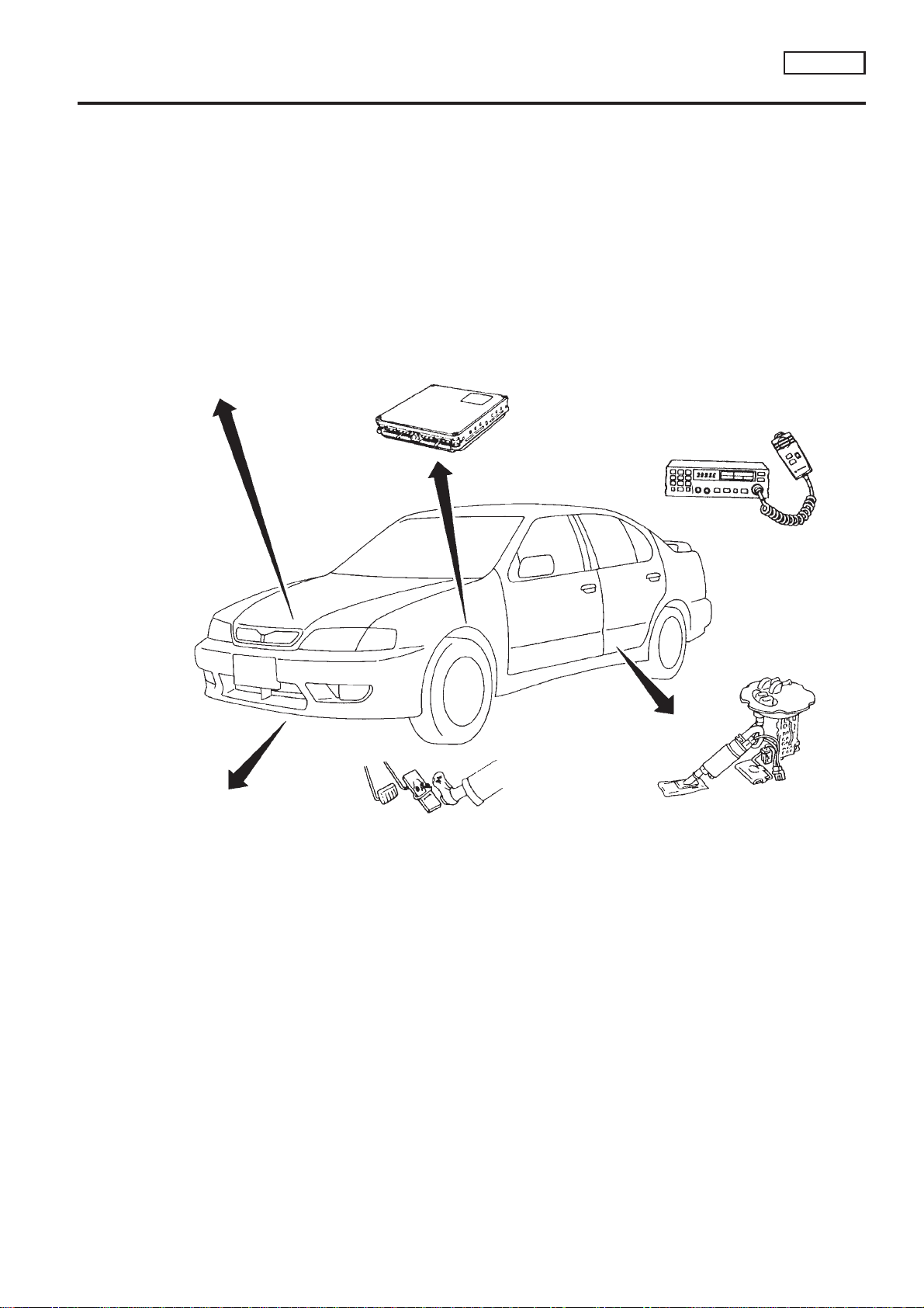
Engine Fuel & Emission Control System
BATTERY
● Always use a 12 volt battery as power
source.
● Do not attempt to disconnect battery
cables while engine is running.
Engine Fuel & Emission Control System
WIRELESS EQUIPMENT
ECM
● Do not disassemble ECM.
● If a battery terminal is disconnected, the
memory will return to the ECM value.
The ECM will now start to self-control at its
initial value. Engine operation can vary
slightly when the terminal is disconnected.
However, this is not an indication of a
problem. Do not replace parts because of
a slight variation.
● When installing C.B. ham radio or a
mobile phone, be sure to observe the
following as it may adversely affect
electronic control systems depending on
installation location.
1) Keep the antenna as far as possible
from the electronic control units.
2) Keep the antenna feeder line more than
20 cm (8 in) away from the harness of
electronic controls.
Do not let them run parallel for a long
distance.
3) Adjust the antenna and feeder line so
that the standing-wave ratio can be kept
smaller.
4) Be sure to ground the radio to vehicle
body.
NCEC0004
ENGINE CONTROL PARTS HANDLING
● Handle mass air flow sensor carefully to
avoid damage.
● Do not disassemble mass air flow
sensor.
● Do not clean mass air flow sensor with
any type of detergent.
● Do not disassemble IAC valve-AAC
valve.
● Even a slight leak in the air intake
system can cause serious problems.
● Do not shock or jar the camshaft position
sensor and crankshaft position sensor.
WHEN STARTING
● Do not depress accelerator pedal when
starting.
● Immediately after starting, do not rev up
engine unnecessarily.
● Do not rev up engine just prior to
shutdown.
EC-SR-11
FUEL PUMP
● Do not operate fuel pump when there is
no fuel in lines.
● Tighten fuel hose clamps to the specified
torque.
ECM HARNESS HANDLING
● Securely connect ECM harness
connectors.
A poor connection can cause an
extremely high (surge) voltage to develop
in coil and condenser, thus resulting in
damage to ICs.
● Keep ECM harness at least 10 cm (4 in)
away from adjacent harness, to prevent
an ECM system malfunctions due to
receiving external noise, degraded
operation of ICs, etc.
● Keep ECM parts and harness dry.
● Before removing parts, turn off ignition
switch and then disconnect battery
ground cable.
SEF331WB

Precautions
PRECAUTIONS
SR20DE
Fasten
Protector
Lever
Loosen
SEF289H
SEF908W
Precautions
NCEC0005
+ Before connecting or disconnecting the ECM harness
connector, turn ignition switch OFF and disconnect negative battery terminal. Failure to do so may damage the
ECM because battery voltage is applied to ECM even if
ignition switch is turned off.
+ When connecting or disconnecting ECM harness
connector, use lever as shown.
When connecting, fasten connector securely with lever
moved until it stops.
+ When connecting or disconnecting pin connectors into or
from ECM, take care not to damage pin terminals (bend or
break).
Make sure that there are not any bends or breaks on ECM
pin terminals when connecting pin connectors.
Bend
Perform ECM input/output signal
inspection before
replacement.
Break
SEF291H
+ Before replacing ECM, perform Terminals and Reference
Value inspection and make sure ECM functions properly.
Refer to EC-SR-104.
MEF040D
+ After performing each TROUBLE DIAGNOSIS, perform
‘‘Overall Function Check’’ or ‘‘DTC Confirmation Procedure’’.
The DTC should not be displayed in the ‘‘DTC Confirmation Procedure’’ if the repair is completed. The ‘‘Overall
Function Check’’ should be a good result if the repair is
completed.
SAT652J
EC-SR-12

Battery
voltage
PRECAUTIONS
Precautions (Cont’d)
SR20DE
+ When measuring ECM signals with a circuit tester, never
allow the two tester probes to contact.
Accidental contact of probes will cause a short circuit and
damage the ECM power transistor.
Short
Solenoid valve
Harness connector
for solenoid valve
Circuit tester
ECM
NG
OK
SEF348N
Wiring Diagrams and Trouble Diagnosis
NCEC0006
When you read Wiring diagrams, refer to the followings:
+ ‘‘HOW TO READ WIRING DIAGRAMS’’ in GI section
+ ‘‘POWER SUPPLY ROUTING’’ for power distribution circuit in
EL section
When you perform trouble diagnosis, refer to the followings:
+ ‘‘HOW TO FOLLOW TEST GROUP IN TROUBLE DIAGNO-
SIS’’ in GI section
+ ‘‘HOW TO PERFORM EFFICIENT DIAGNOSIS FOR AN
ELECTRICAL INCIDENT’’ in GI section
EC-SR-13
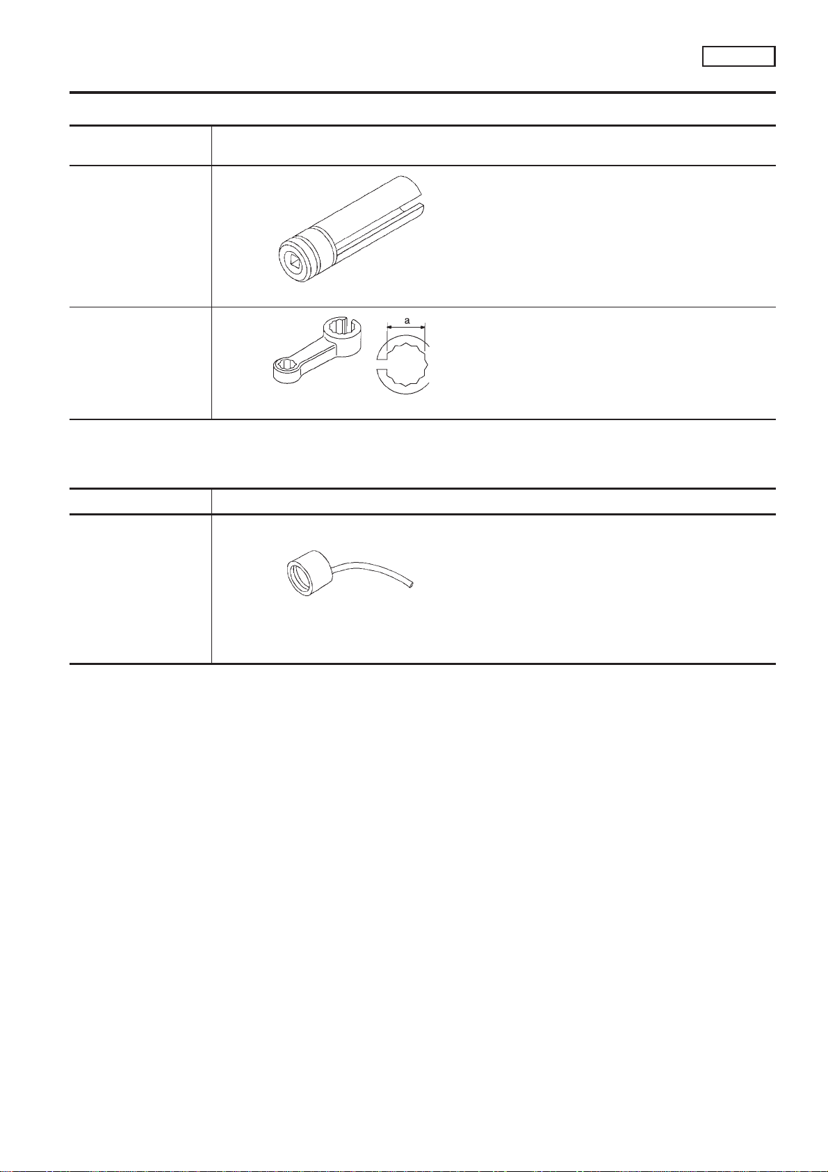
Special Service Tools
PREPARATION
SR20DE
Tool number
Tool name
KV10117100
Heated oxygen sensor
wrench
KV10114400
Heated oxygen sensor
wrench
Tool name Description
Description
NT379
NT636
Special Service Tools
Loosening or tightening front heated oxygen sensor with 22 mm (0.87 in) hexagon nut
Loosening or tightening rear heated oxygen sensor
a: 22 mm (0.87 in)
Commercial Service Tool
NCEC0007
NCEC0008
Fuel filler cap adapter
Checking fuel tank vacuum relief valve opening
pressure
NT653
EC-SR-14
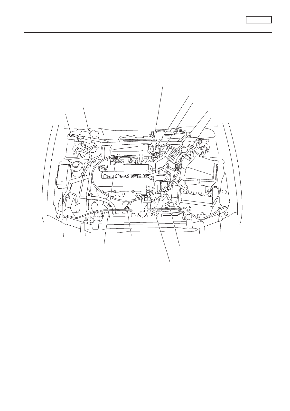
ENGINE AND EMISSION CONTROL OVERALL SYSTEM
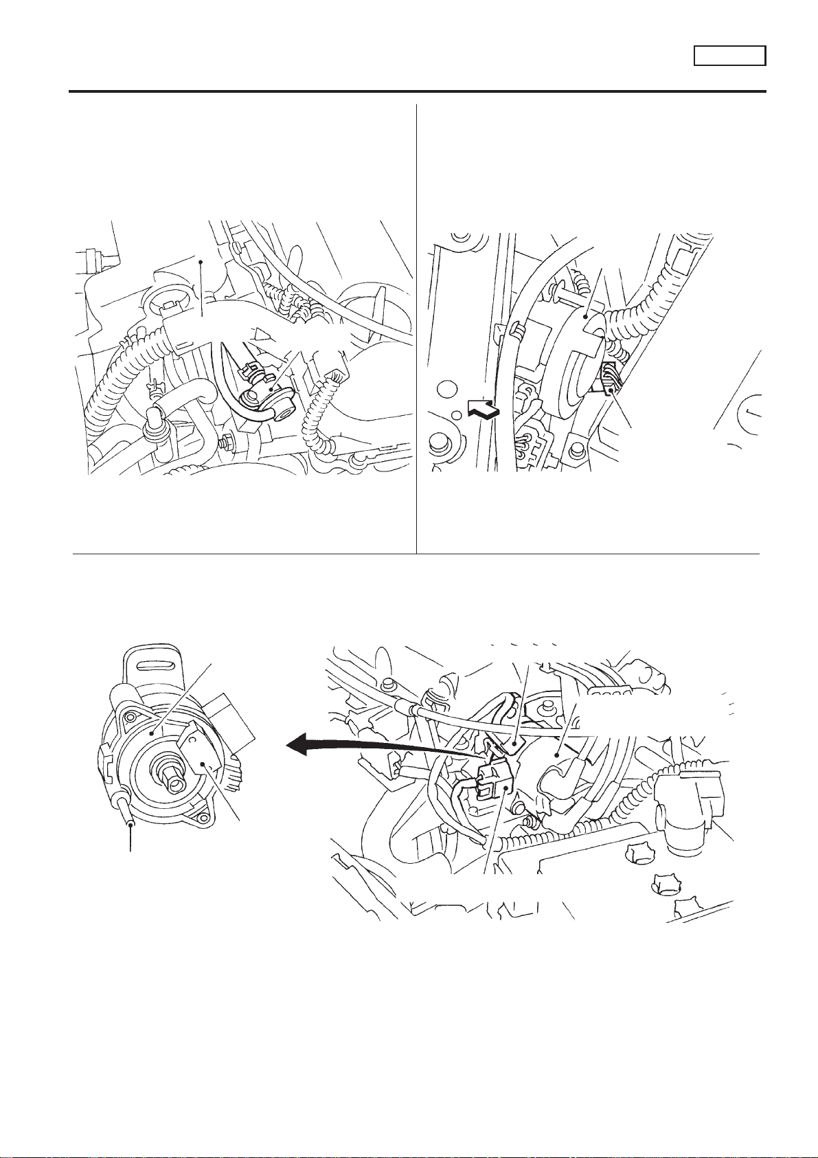
Engine Control Component Parts Location
SR20DE
Power steering
oil pressure switch
EVAP canister
Engine Control Component Parts Location
Throttle position sensor with throttle position switch
IACV-AAC valve
Throttle opener
EGR volume control valve
Mass air flow sensor
NCEC0009
Relay box
Front heated
oxygen sensor
EVAP purge volume
control solenoid valve
Ignition coil, power transistor&
camshaft position sensor built
into distributor
Crankshaft position sensor
Intake air temperature
sensor
SEF186X
EC-SR-15
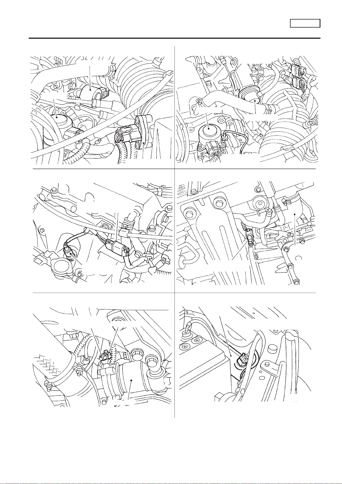
ENGINE AND EMISSION CONTROL OVERALL SYSTEM
Engine Control Component Parts Location (Cont’d)
IACV-AAC valve
EGR valve
Mass air flow sensor
EGR valve
EGR temperature
sensor
View from under the vehicle
Throttle position
sensor and throttle
position switch
Throttle opener
SR20DE
Front heated oxygen
sensor harness connector
Front heated
oxygen sensor
View from under the vehicle
Knock sensor
harness connector
Knock sensor
Battery
Crankshaft position
sensor (OBD)
Air duct
Intake air temperature
sensor harness connector
Radiator
lower hose
Drive shaft
SEF187X
EC-SR-16

ENGINE AND EMISSION CONTROL OVERALL SYSTEM
Engine Control Component Parts Location (Cont’d)
View from under the vehicle
Front exhaust tube
SR20DE
ECM
Fuel tank
gauge unit
harness connector
ECM harness
connector
Fuel pump
harness connector
Glove box
Front
Coolant temperature
sensor harness connector
Rear heated oxygen
sensor harness connector
Rear heated oxygen sensor
Under rear seat cushion
EVAP canister purge
volume control solenoid
Oil filler cap
valve
Harness connector
Front exhaust tube
Power steering
oil pressure switch
EVAP canister (LHD models)
SEF188X
EC-SR-17
ENGINE AND EMISSION CONTROL OVERALL SYSTEM
Engine Control Component Parts Location (Cont’d)
Headlamp
(Left side)
SR20DE
Intake manifold
collector
Power transistor
Fuel pressure
regulator
Front
Terminal for ignition coil
Refrigerant
pressure sensor and
harness connector
Camshaft position sensor,
power transistor and ignition
coil (built into distributor)
Camshaft position
sensor
Metal tip of ignition coil tower
(Terminal of coil circuit)
NOTE: Power transistor, camshaft position sensor,
and ignition coil have to be replaced as a
distributor assembly.
Terminal for camshaft position sensor
and power transistor
EC-SR-18
SEF189X

ENGINE AND EMISSION CONTROL OVERALL SYSTEM
SR20DE
Circuit Diagram
BATTERY
FUSE
SPEED-
(Via fusible link)
VEHICLE SPEED
SENSOR
OMETER
ON or START
IGNITION SWITCH
FUEL PUMP
RELAY
MALFUNCTION
INDICATOR LAMP
FUEL PUMP
EVAP CANISTER
PURGE VOLUME CONTROL
SOLENOID VALVE
Circuit Diagram
FRONT HEATED
OXYGEN SENSOR
REAR HEATED
OXYGEN SENSOR
COOLING
COOLING
FUEL TANK
GAUGE UNIT
(FUEL TANK
IGNITION SWITCH
A/C
RELAY
FAN RELAY
COOLING
FAN MOTOR-2
FAN MOTOR-1
TEMPERATURE
SENSOR)
ON
NATS IMMU
To compressor
To headlamp LH
To lighting switch
XH
FAN SWITCH
A/C
CONTROL PANEL
COMBINATION
METER
NCEC0010
To headlamp relay LH
HD
POWER STEERING
OIL PRESSURE
SWITCH
OFF 1 2 3 4
PARK/NEUTRAL
27
27 10
KNOCK
OA
REAR
WINDOW
DEFOGGER
1044
SENSOR
SWITCH
AC
8811
POSITION SWITCH
ENGINE COOLANT
TEMPERATURE
SENSOR
EGR
TEMPERATURE
SENSOR
INTAKE AIR
TEMPERATURE
SENSOR
DATA LINK CONNECTOR
FUSE
ACC ON STOFF
IGNITION SWITCH
FUSIBLE
LINK
86
114
93
115
101
103
NO.2
NO.1
INJECTOR
105
NO.3
22
107
NO.4
BATTERY
21
14
4623
63
134857
106
108
82
23
503234
116
51
81
46
42
72
70
64
ECM
41
43
110
3135112
67
36
85
75
1667
15
406618
9178
61
73655892111
421617
32
1956555410
717491
9
758
6
41
15
ECM RELAY
IACV-AAC
POWER
TRANSISTOR
DISTRIBUTOR
CONDENSER
IGNITION COIL
CAMSHAFT
POSITION
RESIS-
TOR
SENSOR
VALVE
EGR VOLUME
CONTROL
VALVE
SPARK PLUG
CLOSED
THROTTLE
MASS AIR
FLOW SENSOR
WIDE OPEN
POSITION
SWITCH
THROTTLE
POSITION
SENSOR
REFRIGERANT
PRESSURE
SENSOR
CRANKSHAFT
POSITION
SENSOR
C
TCM
(TRANSMISSION
CONTROL
MODULE)
: CVT models
: With air conditioner
: Without air conditioner
C
ACXHOA
light system
: With XENON headlamp or daytime
HD
HD
: Except
EC-SR-19
YEC221
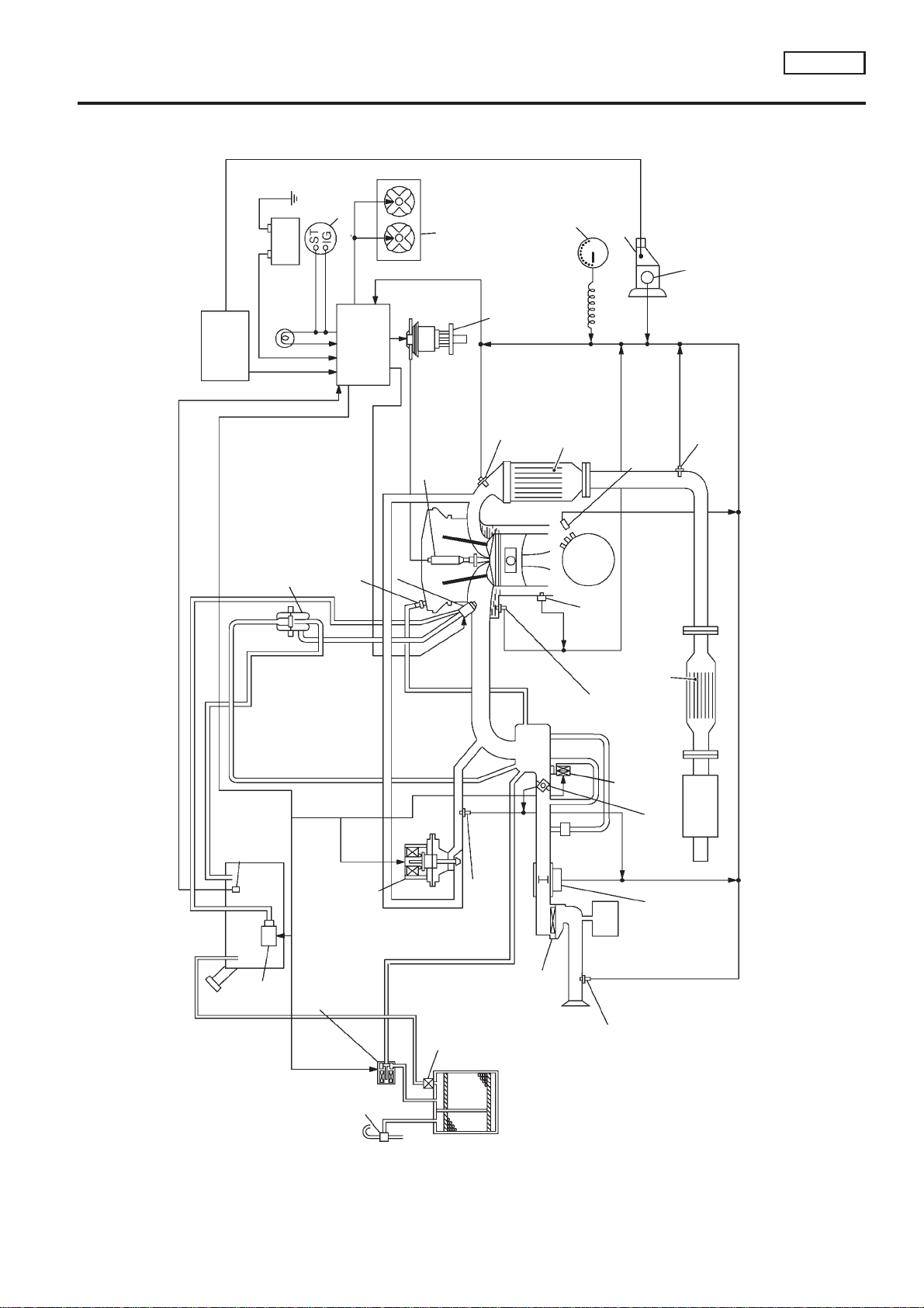
System Diagram
ENGINE AND EMISSION CONTROL OVERALL SYSTEM
SR20DE
TCM
(CVT only)
Fuel
pressure
Battery
MI
regulator
System Diagram
Ignition switch
Cooling fan
ECM
Spark plug
Fuel injector
PCV valve
Ignition coil, power
transistor and
Front heated
oxygen sensor
camshaft position
sensor built into distributor
Vehicle speed
sensor
Three way
catalyst
Transaxle
Crankshaft position
sensor
Park/Neutral position
(PNP) switch
Rear heated
oxygen sensor
NCEC0011
Fuel tank
temperature
sensor
Fuel tank
Fuel
pump
EVAP purge volume
control solenoid valve
EGR volume
control valve
One-way
valve
EGR
temperature
sensor
Air
cleaner
Knock
sensor
Engine
*
coolant
temperature
sensor
IACV-AAC
valve
.
Intake air
temperature
sensor
Three way catalyst
Throttle position sensor
with throttle position switch
Mass air
flow sensor
Muffler
above 1.6 - 2.4MPa and supplies additional air to engine.)
*: Power steering air valve (Valve opens when power steering oil pressure becomes
One-
way
valve
NEF119A
EC-SR-20
ENGINE AND EMISSION CONTROL OVERALL SYSTEM
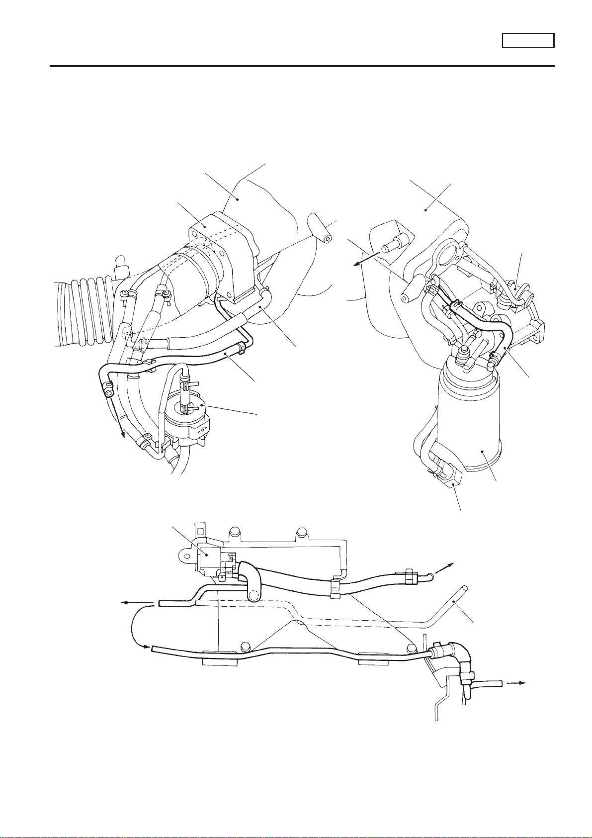
Vacuum Hose Drawing
SR20DE
Vacuum Hose Drawing
Refer to ‘‘System Diagram’’ on EC-SR-20 for vacuum control system.
NOTE:
Do not use soapy water or any type of solvent while installing vacuum hoses or purge hoses.
Rear view (Left side)
Intake manifold collector
Throttle body
To brake
booster
Air hose to
power steering
air valve
EVAP purge line to engine
Rear view (Right side)
Intake manifold collector
NCEC0012
Fuel pressure
regulator
EVAP purge
line to
engine
To EVAP
canister
(RHD models)
To EVAP
canister
(LHD models)
EVAP purge volume
control solenoid valve
Fuel filter
Front view
EVAP canister
(LHD models)
Power steering air valve
To intake manifold
collector
Air tube for power
steering air valve
To EVAP
canister
(RHD models)
EC-SR-21
SEF191X

System Chart
ENGINE AND EMISSION CONTROL OVERALL SYSTEM
SR20DE
System Chart
Input (Sensor) ECM Function Output (Actuator)
+ Camshaft position sensor
+ Mass air flow sensor
+ Engine coolant temperature sensor
+ Front heated oxygen sensor
+ Ignition switch
+ Throttle position sensor
+ PNP switch
+ Air conditioner switch
+ Knock sensor
+ EGR temperature sensor*1
+ Crankshaft position sensor (OBD)*1
+ Tank fuel temperature sensor*1
+ Battery voltage
+ Power steering oil pressure switch
+ Vehicle speed sensor
+ Intake air temperature sensor
+ Rear heated oxygen sensor*2
+ TCM (Transmission control module)*3
+ Closed throttle position switch
+ Electrical load
+ Refrigerant pressure sensor
*1: These sensors are not used to control the engine system. They are used only for the on board diagnosis.
*2: Under normal conditions, this sensor is not for engine control operation.
*3: The DTC related to CVT will be sent to ECM.
Fuel injection & mixture ratio control Injectors
Distributor ignition system Power transistor
Idle air control system IACV-AAC valve
Fuel pump control Fuel pump relay
Front heated oxygen sensor monitor & on
board diagnostic system
EGR control EGR volume control valve
Front and rear heated oxygen sensor
heater control
EVAP canister purge flow control
Cooling fan control Cooling fan relay
Air conditioning cut control Air conditioner relay
Malfunction indicator
(On the instrument panel)
Heated oxygen sensor heater
EVAP canister purge volume control solenoid valve
NCEC0013
EC-SR-22

ENGINE AND EMISSION BASIC CONTROL
SYSTEM DESCRIPTION
Multiport Fuel Injection (MFI) System
DESCRIPTION
Input/Output Signal Chart
Sensor Input Signal to ECM
Camshaft position sensor Engine speed and piston position
Mass air flow sensor Amount of intake air
Engine coolant temperature sensor Engine coolant temperature
Front heated oxygen sensor Density of oxygen in exhaust gas
Multiport Fuel Injection (MFI) System
ECM func-
tion
Actuator
SR20DE
NCEC0014
NCEC0014S01
Throttle position sensor
PNP switch Gear position
Vehicle speed sensor Vehicle speed
Ignition switch Start signal
Air conditioner switch Air conditioner operation
Knock sensor Engine knocking condition
Electrical load Electrical load signal
Battery Battery voltage
Power steering oil pressure switch Power steering operation
Rear heated oxygen sensor* Density of oxygen in exhaust gas
* Under normal conditions, this sensor is not for engine control operation.
Basic Multiport Fuel Injection System
Throttle position
Throttle valve idle position
Fuel injection & mixture ratio
control
Injector
NCEC0014S02
The amount of fuel injected from the fuel injector is determined by the ECM. The ECM controls the length of
time the valve remains open (injection pulse duration). The amount of fuel injected is a program value in the
ECM memory. The program value is preset by engine operating conditions. These conditions are determined
by input signals (for engine speed and intake air) from both the camshaft position sensor and the mass air
flow sensor.
Various Fuel Injection Increase/Decrease Compensation
NCEC0014S03
In addition, the amount of fuel injected is compensated to improve engine performance under various operating conditions as listed below.
<Fuel increase>
+ During warm-up
+ When starting the engine
+ During acceleration
+ Hot-engine operation
+ When selector lever is changed from ‘‘N’’ to ‘‘D’’ (CVT models only)
+ High-load, high-speed operation
<Fuel decrease>
+ During deceleration
+ During high engine speed operation
+ During high vehicle speed operation (M/T models)
+ Extremely high engine coolant temperature
EC-SR-23

ENGINE AND EMISSION BASIC CONTROL
Multiport Fuel Injection (MFI) System (Cont’d)
SYSTEM DESCRIPTION
SR20DE
Mixture Ratio Feedback Control (Closed loop control)
Injection pulse
ECM
Feedback
signal
Front heated
oxygen sensor
Combustion
Injectors
Engine
Fuel
injection
NCEC0014S04
SEF336W
The mixture ratio feedback system provides the best air-fuel mixture ratio for driveability and emission control. The three way catalyst can then better reduce CO, HC and NOx emissions. This system uses a front
heated oxygen sensor in the exhaust manifold to monitor if the engine operation is rich or lean. The ECM
adjusts the injection pulse width according to the sensor voltage signal. For more information about the front
heated oxygen sensor, refer to EC-SR-141. This maintains the mixture ratio within the range of stoichiometric
(ideal air-fuel mixture).
This stage is referred to as the closed loop control condition.
Rear heated oxygen sensor is located downstream of the three way catalyst. Even if the switching characteristics of the front heated oxygen sensor shift, the air-fuel ratio is controlled to stoichiometric by the signal from
the rear heated oxygen sensor.
Open Loop Control
NCEC0014S05
The open loop system condition refers to when the ECM detects any of the following conditions. Feedback
control stops in order to maintain stabilized fuel combustion.
+ Deceleration and acceleration
+ High-load, high-speed operation
+ Malfunction of front heated oxygen sensor or its circuit
+ Insufficient activation of front heated oxygen sensor at low engine coolant temperature
+ High engine coolant temperature
+ During warm-up
+ When starting the engine
Mixture Ratio Self-learning Control
NCEC0014S06
The mixture ratio feedback control system monitors the mixture ratio signal transmitted from the front heated
oxygen sensor. This feedback signal is then sent to the ECM. The ECM controls the basic mixture ratio as
close to the theoretical mixture ratio as possible. However, the basic mixture ratio is not necessarily controlled
as originally designed. Both manufacturing differences (i.e., mass air flow sensor hot film) and characteristic
changes during operation (i.e., injector clogging) directly affect mixture ratio.
Accordingly, the difference between the basic and theoretical mixture ratios is monitored in this system. This
is then computed in terms of ‘‘injection pulse duration’’ to automatically compensate for the difference between
the two ratios.
‘‘Fuel trim’’ refers to the feedback compensation value compared against the basic injection duration. Fuel trim
includes short term fuel trim and long term fuel trim.
‘‘Short term fuel trim’’ is the short-term fuel compensation used to maintain the mixture ratio at its theoretical
value. The signal from the front heated oxygen sensor indicates whether the mixture ratio is RICH or LEAN
compared to the theoretical value. The signal then triggers a reduction in fuel volume if the mixture ratio is
rich, and an increase in fuel volume if it is lean.
‘‘Long term fuel trim’’ is overall fuel compensation carried out long-term to compensate for continual deviation
of the short term fuel trim from the central value. Such deviation will occur due to individual engine differences,
wear over time and changes in the usage environment.
EC-SR-24
ENGINE AND EMISSION BASIC CONTROL
SYSTEM DESCRIPTION
Multiport Fuel Injection (MFI) System (Cont’d)
SR20DE
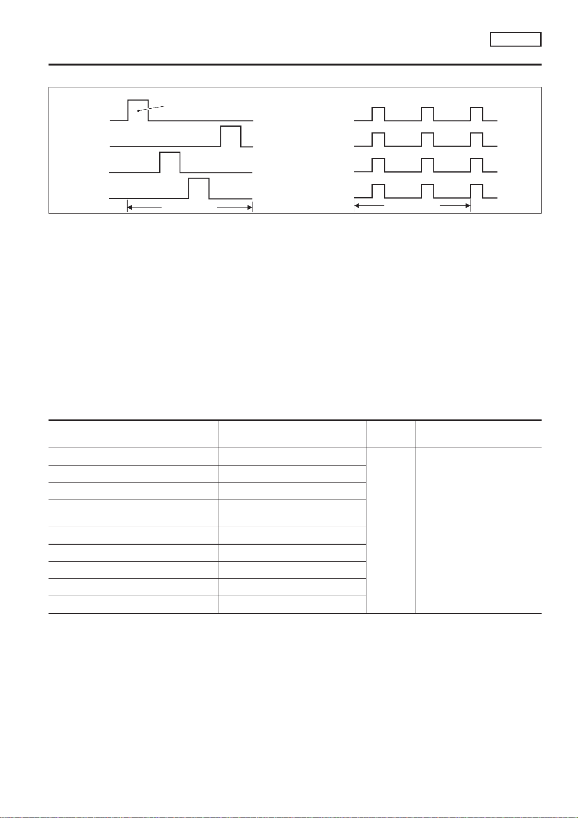
Fuel Injection Timing
● Sequential multiport fuel injection system
No. 1 cylinder
No. 2 cylinder
No. 3 cylinder
No. 4 cylinder
Injection pulse
1 engine cycle
No. 1 cylinder
No. 2 cylinder
No. 3 cylinder
No. 4 cylinder
● Simultaneous multiport fuel injection system
1 engine cycle
NCEC0014S07
SEF337W
Two types of systems are used.
Sequential Multiport Fuel Injection System
NCEC0014S0701
Fuel is injected into each cylinder during each engine cycle according to the firing order. This system is used
when the engine is running.
Simultaneous Multiport Fuel Injection System
NCEC0014S0702
Fuel is injected simultaneously into all four cylinders twice each engine cycle. In other words, pulse signals of
the same width are simultaneously transmitted from the ECM.
The four injectors will then receive the signals two times for each engine cycle.
This system is used when the engine is being started and/or if the fail-safe system (CPU) is operating.
Fuel Shut-off
NCEC0014S08
Fuel to each cylinder is cut off during deceleration or operation of the engine at excessively high speeds.
Distributor Ignition (DI) System
DESCRIPTION
Input/Output Signal Chart
Sensor Input Signal to ECM
Camshaft position sensor Engine speed and piston position
Mass air flow sensor Amount of intake air
Engine coolant temperature sensor Engine coolant temperature
Throttle position sensor
Vehicle speed sensor Vehicle speed
Ignition switch Start signal
Knock sensor Engine knocking
PNP switch Gear position
Battery Battery voltage
Throttle position
Throttle valve idle position
ECM func-
tion
Ignition timing control
NCEC0015
NCEC0015S01
Actuator
Power transistor
EC-SR-25

ENGINE AND EMISSION BASIC CONTROL
Distributor Ignition (DI) System (Cont’d)
SYSTEM DESCRIPTION
SR20DE
System Description
Tp
(msec)
1.75
1.50
1.25
1.00
Injection pulse width
0.75
600 1,000 1,400 1,800 2,200
Engine speed (rpm)
N
SEF742M
NCEC0015S02
The ignition timing is controlled by the ECM to maintain the best air-fuel ratio for every running condition of
the engine. The ignition timing data is stored in the ECM. This data forms the map shown above.
The ECM receives information such as the injection pulse width and camshaft position sensor signal. Computing this information, ignition signals are transmitted to the power transistor.
e.g., N: 1,800 rpm, Tp: 1.50 msec
A°BTDC
During the following conditions, the ignition timing is revised by the ECM according to the other data stored
in the ECM.
+ At starting
+ During warm-up
+ At idle
+ At low battery voltage
+ During acceleration
The knock sensor retard system is designed only for emergencies. The basic ignition timing is programmed
within the anti-knocking zone, if recommended fuel is used under dry conditions. The retard system does not
operate under normal driving conditions.
If engine knocking occurs, the knock sensor monitors the condition. The signal is transmitted to the ECM. The
ECM retards the ignition timing to eliminate the knocking condition.
Air Conditioning Cut Control
DESCRIPTION
Input/Output Signal Chart
Sensor Input Signal to ECM
Air conditioner switch Air conditioner ‘‘ON’’ signal
PNP switch Neutral position
Throttle position sensor Throttle valve opening angle
Camshaft position sensor Engine speed
Engine coolant temperature sensor Engine coolant temperature
Ignition switch Start signal
Refrigerant pressure sensor Refrigerant pressure
Vehicle speed sensor Vehicle speed
Power steering oil pressure switch Power steering operation
System Description
This system improves engine operation when the air conditioner is used.
Under the following conditions, the air conditioner is turned off.
+ When the accelerator pedal is fully depressed.
+ When cranking the engine.
ECM func-
Air conditioner cut
control
tion
NCEC0016
NCEC0016S01
Actuator
Air conditioner relay
NCEC0016S02
EC-SR-26
ENGINE AND EMISSION BASIC CONTROL
SYSTEM DESCRIPTION
Air Conditioning Cut Control (Cont’d)
+ At high engine speeds.
+ When the engine coolant temperature becomes excessively high.
+ When operating power steering during low engine speed or low vehicle speed.
+ When engine speed is excessively low.
Fuel Cut Control (at no load & high engine speed)
DESCRIPTION
Input/Output Signal Chart
Sensor Input Signal to ECM
Vehicle speed sensor Vehicle speed
PNP switch Neutral position
Throttle position sensor Throttle position
Engine coolant temperature sensor Engine coolant temperature
Camshaft position sensor Engine speed
ECM func-
tion
Fuel cut
control
SR20DE
NCEC0017
NCEC0017S01
Actuator
Injectors
If the engine speed is above 3,950 rpm with no load, (for example, in Neutral and engine speed over 4,000
rpm) fuel will be cut off after some time. The exact time when the fuel is cut off varies based on engine speed.
Fuel cut will operate until the engine speed reaches 1,150 rpm, then fuel cut is cancelled.
NOTE:
This function is different from deceleration control listed under ‘‘Multiport Fuel Injection (MFI)
System’’, EC-SR-23.
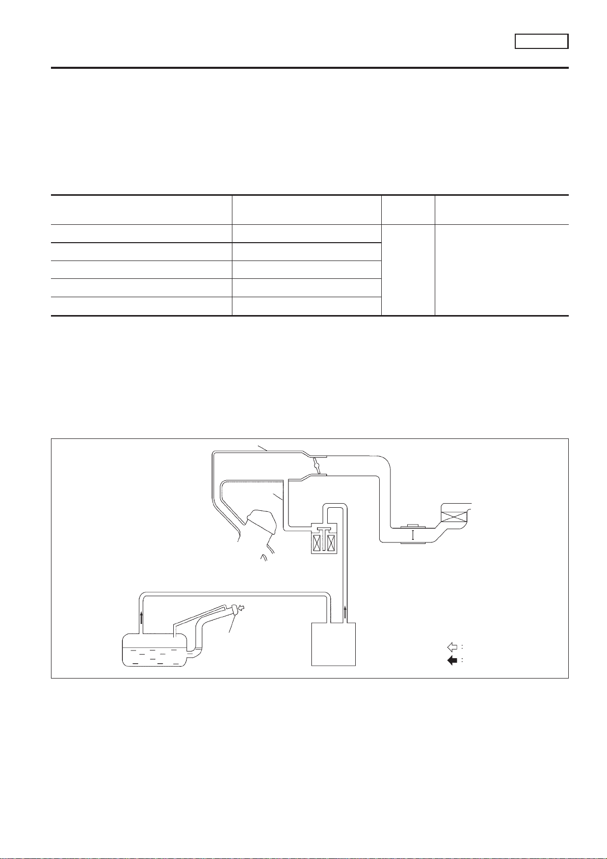
Evaporative Emission System
DESCRIPTION
Intake manifold
Purge line
EVAP canister
purge volume
control solenoid
valve
Relief of vacuum
Throttle body
NCEC0018
Fuel tank
Sealing gas cap with
pressure relief valve
and vacuum relief
valve
EVAP
canister
Air
Fuel vapor
SEF916W
The evaporative emission system is used to reduce hydrocarbons emitted into the atmosphere from the fuel
system. This reduction of hydrocarbons is accomplished by activated charcoals in the EVAP canister.
The fuel vapor in the sealed fuel tank is led into the EVAP canister which contains activated carbon and the
vapor is stored there when the engine is not operating or when refueling to the fuel tank.
The vapor in the EVAP canister is purged by the air through the purge line to the intake manifold when the
engine is operating.
EVAP canister purge volume control solenoid valve is controlled by ECM. When the engine operates, the flow
EC-SR-27
ENGINE AND EMISSION BASIC CONTROL
SYSTEM DESCRIPTION
Evaporative Emission System (Cont’d)
rate of vapor controlled by EVAP canister purge volume control solenoid valve is proportionally regulated as
the air flow increases.
EVAP canister purge volume control solenoid valve also shuts off the vapor purge line during decelerating and
idling.
SR20DE
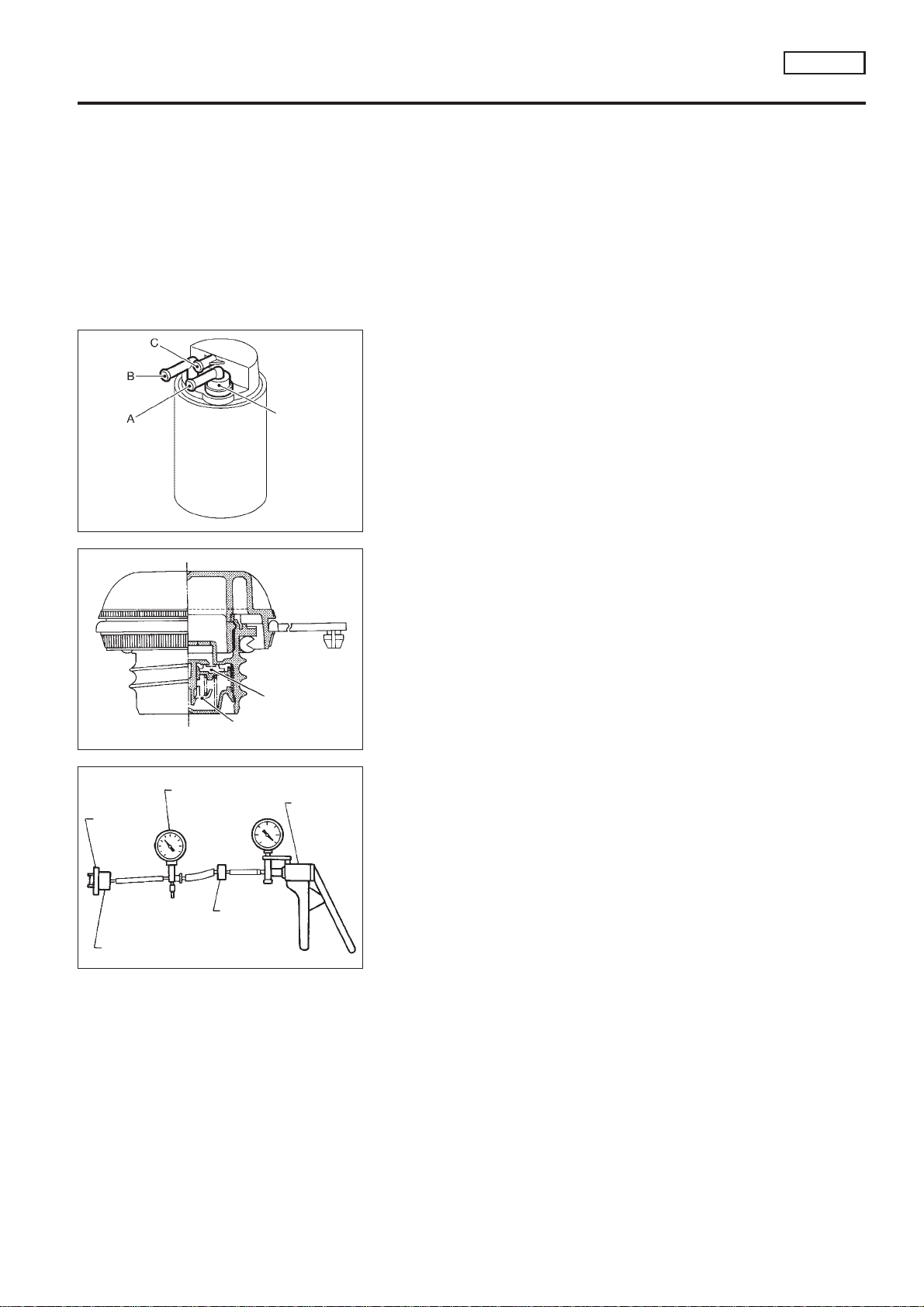
Valve A
Check valve
Valve B
SEF917W
SEF918W
INSPECTION
EVAP Canister
NCEC0019
NCEC0019S01
Check EVAP canister as follows:
1. Block port B. Orally blow air through port A. Check that air
flows freely through port C with check valve resistance.
2. Block port A. Orally blow air through port B. Check that air
flows freely through port C.
Fuel Tank Vacuum Relief Valve (Built into fuel filler
cap)
1. Wipe clean valve housing.
2. Check valve opening pressure and vacuum.
Pressure:
16.0 - 20.0 kPa (0.16 - 0.20 bar, 0.163 - 0.204
2
kg/cm
Vacuum:
−6.0 to −3.5 kPa (−0.060 to −0.035 bar, −0.061 to
−0.036 kg/cm
3. If out of specification, replace fuel filler cap as an assembly.
, 2.32 - 2.90 psi)
2
, −0.87 to −0.51 psi)
NCEC0019S03
Vacuum/Pressure gauge
Fuel filler
cap
Fuel filler cap adapter
One-way
valve
Vacuum/
Pressure
pump
SEF943S
Evaporative Emission (EVAP) Canister Purge Volume
Control Solenoid Valve
Refer to EC-SR-263.
Tank Fuel Temperature Sensor
Refer to EC-SR-220.
NCEC0019S07
NCEC0019S08
EC-SR-28
ENGINE AND EMISSION BASIC CONTROL
SYSTEM DESCRIPTION
Evaporative Emission System (Cont’d)
SR20DE
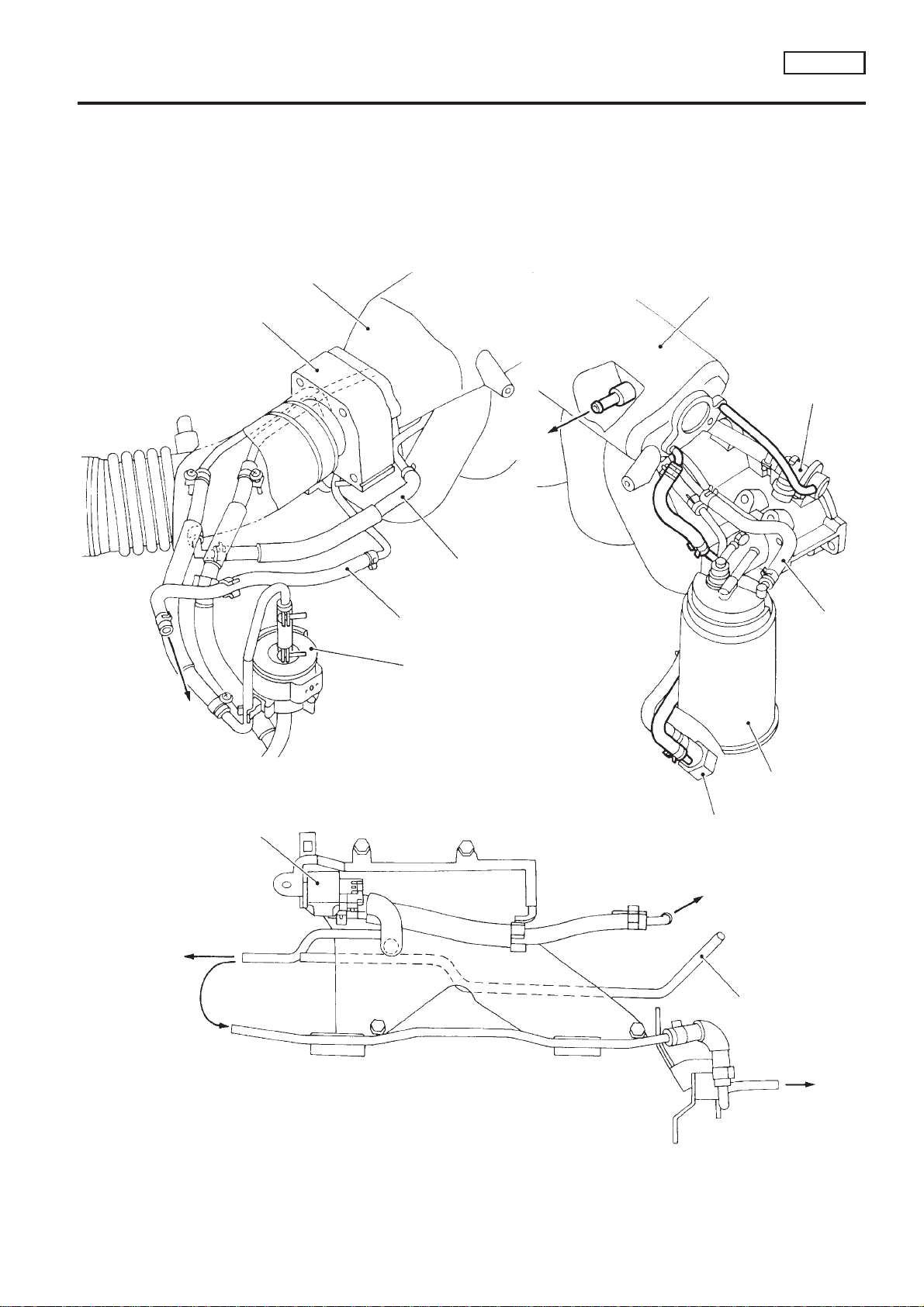
EVAPORATIVE EMISSION LINE DRAWING
NOTE:
Do not use soapy water or any type of solvent while installing vacuum hoses or purge hoses.
Rear view (Left side)
Throttle body
Intake manifold collector
To brake
booster
Air hose to
power steering
air valve
Rear view (Right side)
Intake manifold collector
NCEC0020
Fuel pressure
regulator
To EVAP
canister
(RHD models)
To EVAP
canister
(LHD models)
EVAP purge volume
control solenoid valve
EVAP purge line to engine
Fuel filter
Front view
EVAP canister
(LHD models)
Power steering air valve
To intake manifold
collector
Air tube for power
steering air valve
EVAP purge
line to
engine
EC-SR-29
To EVAP
canister
(RHD models)
SEF193X
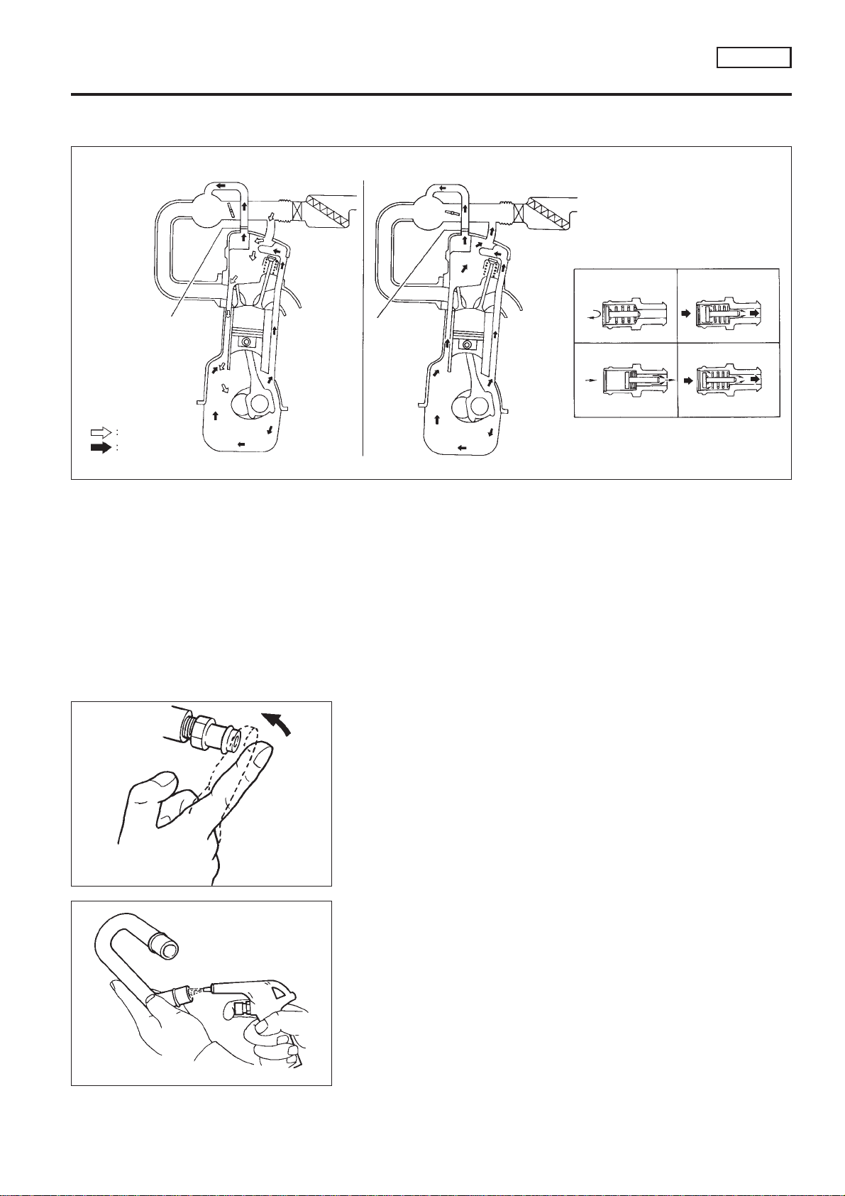
Positive Crankcase Ventilation
DESCRIPTION
ENGINE AND EMISSION BASIC CONTROL
SYSTEM DESCRIPTION
Positive Crankcase Ventilation
SR20DE
NCEC0022
Idling or
decelerating
Fresh air
Blow-by gas
Cruising
Acceleration or high load
PCV valve
PCV valve operation
Engine not running
or backfiring
Idling or
decelerating
Cruising
Acceleration
or high load
SEF921W
This system returns blow-by gas to the intake collector.
The positive crankcase ventilation (PCV) valve is provided to conduct crankcase blow-by gas to the intake
manifold.
During partial throttle operation of the engine, the intake manifold sucks the blow-by gas through the PCV
valve.
Normally, the capacity of the valve is sufficient to handle any blow-by and a small amount of ventilating air.
The ventilating air is then drawn from the air duct into the crankcase. In this process the air passes through
the hose connecting air inlet tubes to rocker cover.
Under full-throttle condition, the manifold vacuum is insufficient to draw the blow-by flow through the valve.
The flow goes through the hose connection in the reverse direction.
On vehicles with an excessively high blow-by, the valve does not meet the requirement. This is because some
of the flow will go through the hose connection to the intake collector under all conditions.
SEC137A
ET277
INSPECTION
PCV (Positive Crankcase Ventilation) Valve
NCEC0023
NCEC0023S01
With engine running at idle, remove PCV valve from breather separator. A properly working valve makes a hissing noise as air passes
through it. A strong vacuum should be felt immediately when a finger is placed over the valve inlet.
Ventilation Hose
NCEC0023S02
1. Check hoses and hose connections for leaks.
2. Disconnect all hoses and clean with compressed air. If any
hose cannot be freed of obstructions, replace.
EC-SR-30
Loading...