


Micra 2003
Table of contents
 Loading...
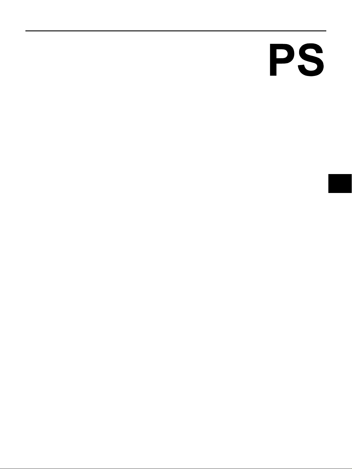
POWER STEERING SYSTEM
G STEERING
A
B
SECTION
POWER STEERING SYSTEM
CONTENTS
PRECAUTIONS .......................................................... 2
Precautions for Supplemental Restraint System
(SRS)“AIRBAG”and“SEATBELTPRE-TEN-
SIONER” .................................................................. 2
Caution: .................................................................... 2
PREPARATION ........................................................... 3
Special Service Tools ............................................... 3
NOISE, VIBRATION AND HARSHNESS (NVH)
TROUBLESHOOTING ................................................ 4
NVH Trouble Shooting Chart .................................... 4
STEERING WHEEL .................................................... 5
On Board Inspection and Service ............................ 5
PLAY INSPECTION .............................................. 5
NEUTRAL POSITION INSPECTION .................... 5
STEERING TORQUE INSPECTION .................... 5
STEERING ANGLE INSPECTION ........................ 5
Removal and Installation .......................................... 6
STEERING COLUMN ................................................. 7
Removal and Installation .......................................... 7
REMOVAL OF STEERING COLUMN ASSEM-
BLY ........................................................................ 7
INSPECTION AFTER REMOVAL OF STEER-
ING COLUMN ASSEMBLY ................................... 8
INSTALLATION OF STEERING COLUMN
ASSEMBLY ...........................................................8
CHECK AFTER STEERING COLUMN ASSEM-
BLYINSTALLATION ..............................................8
POWER STEERING GEAR AND LINKAGE ..............9
Removal and Installation ..........................................9
REMOVAL .............................................................9
INSTALLATION .....................................................9
Disassembly and Assembly .................................... 10
COMPONENTPARTSLOCATION(R24TTYPE)...10
DISASSEMBLY ...................................................10
INSPECTION AFTER DISASSEMBLY ................10
ASSEMBLY ......................................................... 11
SERVICE DATA AND SPECIFICATIONS (SDS) ......13
Wheel .....................................................................13
Steering Angle ........................................................13
Steering Column .....................................................13
Steering Linkage ..................................................... 13
Tightening Torque ...................................................14
C
D
E
F
PS
H
I
J
K
L
PS-1
M

PRECAUTIONS
PRECAUTIONS
PFP:00001
Precautions for Supplemental Restraint System (SRS) “AIR BAG” and “SEAT BELT PRE-TENSIONER”
The Supplemental Restraint System such as “AIR BAG” and “SEAT BELT PRE-TENSIONER”, used along
with a front seat belt, helps to reduce the risk or severity of injury to the driver and front passenger for certain
types of collision. Information necessary to service the system safely is included in the SRS and SB section of
this Service Manual.
WARNING:
● To avoid rendering the SRS inoperative, which could increase the risk of personal injury or death
in the event of a collision which would result in air bag inflation, all maintenance must be performed by an authorized NISSAN/INFINITI dealer.
● Improper maintenance, including incorrect removal and installation of the SRS, can lead to per-
sonal injury caused by unintentional activation of the system. For removal of Spiral Cable and Air
Bag Module, see the SRS section.
● Do not use electrical test equipment on any circuit related to the SRS unless instructed to in this
Service Manual. SRS wiring harnesses can be identified by yellow and/or orange harnesses or
harness connectors.
Caution:
● Always follow the warnings and the cautions below in disassembly procedures:
– Work in a clean, dust-free place. No dustproof device is necessary.
– Clean the outside of the unit before disassembly.
– Clean the parts to be disassembled. Care must be taken not to allow any dirt or other foreign materials to
enter or come in contact with the parts.
– Assemble the disassembled parts properly, following the order shown in the manual. If work has been
suspended in the middle of assembly, place a clean cover over the parts to prevent them from being contaminated.
– Use paper towels when removing dirt and other foreign materials. Cloth shop towels can leave lint on the
cleaned parts that might affect the operation of the parts.
– Clean disassembled parts with kerosene (except rubber parts), and then dry them thoroughly with an air
blower or paper towels.
EGS001B3
EGS000J1
PS-2
PREPARATION
PREPARATION PFP:00002
Special Service Tools
EGS000J2
A
Preload gauge
ST3127S000
Description Application
● Checking steering torque
● Pinion gear rotating torque measurement
for steering gear
ZZA0806D
B
C
D
E
F
PS
H
I
K
M
J
L
PS-3
NOISE, VIBRATION AND HARSHNESS (NVH) TROUBLESHOOTING
NOISE, VIBRATION AND HARSHNESS (NVH) TROUBLESHOOTING
PFP:00003
NVH Trouble Shooting Chart
Use the chart below to help you find the cause of the symptom. If necessary, repair or replace these parts.
Reference page
PS-9
PS-9
PS-9
–
PS-5
–
PS-7
PS-7
PS-7
PS-9
NVH in WT section
NVH in WT section
NVH in FAX section
NVH in FAX, RAX, FSU, RSU section
EGS000J3
NVHinBRsection
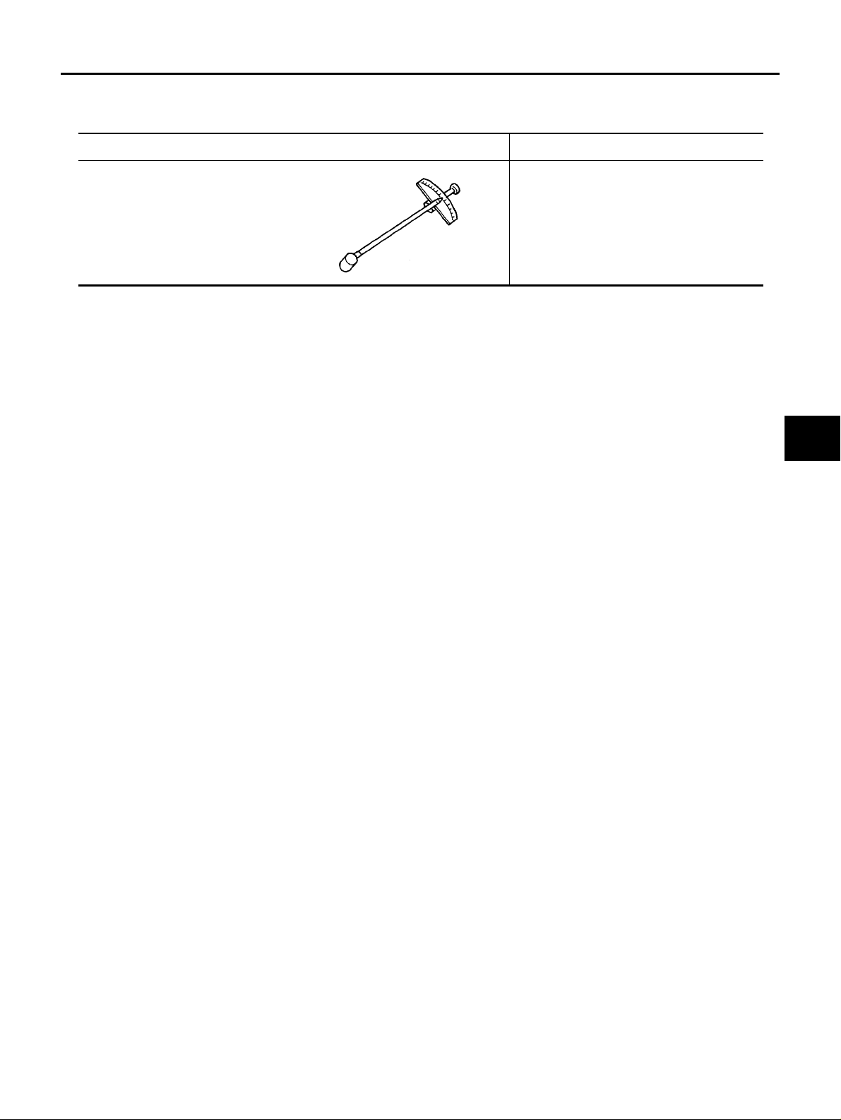
Possible cause and SUSPECTED PARTS
Symptom STEERING
×: Applicable
Tie-rod ball joint tensile force
Tie-rod ball joint sliding torque
Tie-rod ball joint end play
Steering wheel play
Improper steering wheel
Improper installation or looseness or tilt lock lever
Mounting rubber deterioration
Steering column deformation or damage
Improper installation or looseness of steering column
Steering linkage looseness
AXLE AND SUSPENSION
TIRES
ROAD WHEEL
DRIVE SHAFT
BRAKES
Noise ×××× ×××× ×
Shake ××× ×××× ×
Vibration ЧЧЧЧЧ ×× ×
Shimmy ××× ×××× ×
Judder ××××××
PS-4
STEERING WHEEL
STEERING WHEEL PFP:48430
On Board Inspection and Service
PLAY INSPECTION
1. Turn steering wheel to the straight-ahead position. Start engine and lightly turn steering wheel clockwise
and counterclockwise until the front wheels start moving. Measure the travel to the starting point on the
circumference of steering wheel. If play is outside the specified range, check steering gear assembly ,front
suspension, axles, and steering column for proper installation.
Steering wheel play inspection standard : 0 - 35 mm (0 - 1.38 in)
2. Check steering wheel for vertical, horizontal, or axial play.
Steering wheel axial end play : 0 mm (0 in)
● Lift vehicle and check steering gear nuts and bolts for looseness.
Tightening torque : 85 - 103 N·m (8.7 - 10.5 kg-m, 63 - 75 ft-lb)
NEUTRAL POSITION INSPECTION
● After wheel alignment inspection, perform neutral position inspection. Refer to FSU-6, "Wheel Alignment"
.
● Set vehicle to the straight-ahead position and confirm steering wheel is in the neutral position.
● If it is not in the neutral position, loosen lock nut on tie-rod. Then adjust until the amount of left and right
becomes equal.
EGS000J4
A
B
C
D
E
F
PS
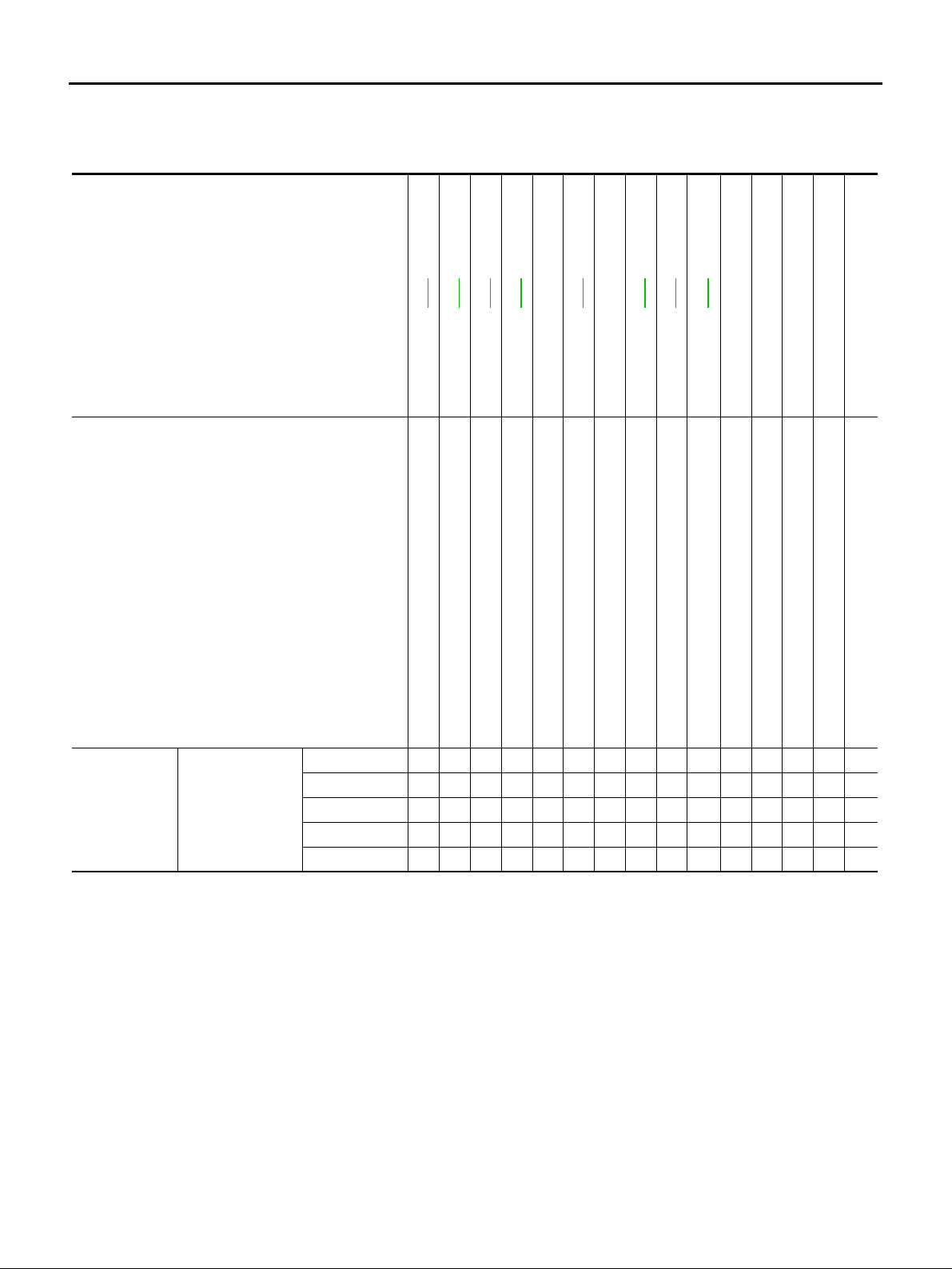
STEERING TORQUE INSPECTION
1. Stop vehicle on a dry flat paved road and apply parking brake.
2. Remove air bag module. Refer to SRS-36, "
DRIVER AIR BAG MODULE" .
3. Start engine and use a preload gauge (SST) to check steering
wheel torque.
Steering torque : 1.8 - 5.6 N·m (0.18 - 0.57 kg-m,
16 - 49 in-lb) or less
4. When torque is outsidethe standard, check steeringcolumn and
steering gear. If any non-standard condition is detected, replace
if necessary.
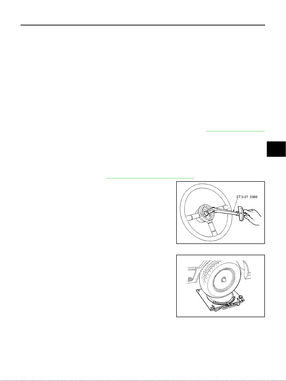
STEERING ANGLE INSPECTION
● After toe-in inspection, check the steering angle. Place the front
wheels on turning radius gauges and the rear wheels on stands
so that the vehicle can be level. Check the maximum inner and
outer wheel steering angles for LH and RH road wheels.
STA0005D
H
I
J
K
L
M
PS-5
FAA0016D
Loading...